US8097073B2 - Dehumidifier - Google Patents
Dehumidifier Download PDFInfo
- Publication number
- US8097073B2 US8097073B2 US11/991,548 US99154806A US8097073B2 US 8097073 B2 US8097073 B2 US 8097073B2 US 99154806 A US99154806 A US 99154806A US 8097073 B2 US8097073 B2 US 8097073B2
- Authority
- US
- United States
- Prior art keywords
- barrier
- drain hose
- base
- hose
- condensed water
- Prior art date
- Legal status (The legal status is an assumption and is not a legal conclusion. Google has not performed a legal analysis and makes no representation as to the accuracy of the status listed.)
- Expired - Fee Related, expires
Links
- XLYOFNOQVPJJNP-UHFFFAOYSA-N water Substances O XLYOFNOQVPJJNP-UHFFFAOYSA-N 0.000 claims abstract description 78
- 230000004888 barrier function Effects 0.000 claims abstract description 58
- 230000008878 coupling Effects 0.000 claims description 20
- 238000010168 coupling process Methods 0.000 claims description 20
- 238000005859 coupling reaction Methods 0.000 claims description 20
- 230000035515 penetration Effects 0.000 claims description 15
- 238000007599 discharging Methods 0.000 claims description 11
- 238000009434 installation Methods 0.000 claims description 11
- 239000006200 vaporizer Substances 0.000 description 19
- 238000000034 method Methods 0.000 description 13
- 230000008569 process Effects 0.000 description 11
- 239000003507 refrigerant Substances 0.000 description 9
- 230000008901 benefit Effects 0.000 description 5
- 230000033001 locomotion Effects 0.000 description 5
- 230000007257 malfunction Effects 0.000 description 4
- 238000012423 maintenance Methods 0.000 description 3
- 230000004048 modification Effects 0.000 description 2
- 238000012986 modification Methods 0.000 description 2
- 230000005540 biological transmission Effects 0.000 description 1
- 238000007791 dehumidification Methods 0.000 description 1
- 230000000694 effects Effects 0.000 description 1
- 238000001914 filtration Methods 0.000 description 1
- 230000006698 induction Effects 0.000 description 1
- 230000007246 mechanism Effects 0.000 description 1
- 230000008439 repair process Effects 0.000 description 1
- 238000000926 separation method Methods 0.000 description 1
- 230000008016 vaporization Effects 0.000 description 1
Images





Classifications
-
- F—MECHANICAL ENGINEERING; LIGHTING; HEATING; WEAPONS; BLASTING
- F24—HEATING; RANGES; VENTILATING
- F24F—AIR-CONDITIONING; AIR-HUMIDIFICATION; VENTILATION; USE OF AIR CURRENTS FOR SCREENING
- F24F3/00—Air-conditioning systems in which conditioned primary air is supplied from one or more central stations to distributing units in the rooms or spaces where it may receive secondary treatment; Apparatus specially designed for such systems
- F24F3/12—Air-conditioning systems in which conditioned primary air is supplied from one or more central stations to distributing units in the rooms or spaces where it may receive secondary treatment; Apparatus specially designed for such systems characterised by the treatment of the air otherwise than by heating and cooling
- F24F3/14—Air-conditioning systems in which conditioned primary air is supplied from one or more central stations to distributing units in the rooms or spaces where it may receive secondary treatment; Apparatus specially designed for such systems characterised by the treatment of the air otherwise than by heating and cooling by humidification; by dehumidification
-
- F—MECHANICAL ENGINEERING; LIGHTING; HEATING; WEAPONS; BLASTING
- F24—HEATING; RANGES; VENTILATING
- F24F—AIR-CONDITIONING; AIR-HUMIDIFICATION; VENTILATION; USE OF AIR CURRENTS FOR SCREENING
- F24F13/00—Details common to, or for air-conditioning, air-humidification, ventilation or use of air currents for screening
- F24F13/22—Means for preventing condensation or evacuating condensate
- F24F13/222—Means for preventing condensation or evacuating condensate for evacuating condensate
Definitions
- the present invention relates to a dehumidifier, and more particularly, to a dehumidifier that can easily attach and detach a compressor to or from a barrier and fix a drain hose to the barrier.
- a dehumidifier is an apparatus for sucking indoor humid air into a cabinet, removing moisture from the humid air by allowing the humid air to pass through a heat exchanger having a condenser and a vaporizer along which refrigerants flow, then discharging the air from which the moisture is removed to an indoor room.
- a drain hose is directly connected to a drain hole formed on the drain pan to drain the condensed water out of the dehumidifier.
- the present invention is directed to a dehumidifier that substantially obviates one or more problems due to limitations and disadvantages of the related art.
- An object of the present invention is to provide a dehumidifier that can fix a drain hose which is not being used during discharging of condensed water stored in a bucket.
- Another object of the present invention is to provide a dehumidifier that can prevent the drain hose from moving by flow of the condensed water during the discharging of the condensed water through the drain hose.
- Still another object of the present invention is to provide a dehumidifier that can separate a compressor using a minimum working process by separating a small amount of internal components surrounding the compressor when there is a need to have a maintenance service due to the malfunction of the compressor.
- Still yet another object of the present invention is to provide a dehumidifier that can mount a compressor using a minimum working process after the repair of the compressor is finished.
- a dehumidifier including: a base; a barrier installed on the base to collect condensed water and provided with a water collection hole for discharging the condensed water; a bucket assembly coupled to the barrier and storing the condensed water; a drain hose for discharging the condensed water to an external side, one of the bucket assembly and the drain hose being selectively connected to the water collecting hole; and a hose fixing unit for fixing the drain hose.
- the user can discharge the condensed water collected in a drain pan using any one of the bucket or the drain hose.
- the hose fixing unit for fixing the hose is formed on the barrier, the movement of the drain hose can be prevented when the condensed water is discharge through the drain hose and the drain hose can be stably fixed when it is not being used.
- the compressor can be easily separated by separating only the bucket and the rear panel and inserting a tool through the penetration portion when there is a need to have a maintenance service due to the malfunction of the compressor.
- FIG. 1 is a perspective view of a dehumidifier according to an embodiment of the present invention
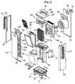
- FIG. 2 is an exploded perspective view of the dehumidifier of FIG. 1 ;
- FIG. 3 is an exploded perspective view of a bucket assembly according to an embodiment of the present invention.
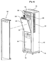
- FIG. 6 is an operational view for illustrating a separating process of the bucket assembly according to an embodiment of the present invention.
- FIG. 7 is an exploded perspective view of a filter assembly according to an embodiment of the present invention.
- FIG. 9 is a view illustrating an operation of the dehumidifier of the present invention.
- FIG. 1 is a perspective view of a dehumidifier according to an embodiment of the present invention and FIG. 2 is an exploded perspective view of the dehumidifier of FIG. 1 .
- the dehumidifier of the present invention further includes a base 70 formed a bottom of the cabinet 60 , a barrier 80 vertically installed on the base 70 and dividing the base into front and rear portions, a bucket assembly 90 installed on the barrier 80 to store the condensed water condensed on a surface of the vaporizer, and a filter assembly 120 installed on an upper portion of the barrier 80 to filtering off foreign off foreign objects contained in air introduced into the cabinet 60 and directed to the blower fan assembly 50 .
- wheels 71 are installed on a bottom of the base 70 and the barrier 80 is installed on the base 70 .
- the bucket assembly 90 is installed on the front portion of the base 70 and the compressor 10 is installed on the rear portion of the base 70 .
- the filter assembly 120 , vaporizer 40 , condenser 20 , and blower fan assembly 50 are installed on the barrier 80 from the front portion to the rear portion in this order.
- the vaporizer 40 and the condenser 20 are spaced apart from each other and integrally coupled to each other.
- a drain pan 83 is formed on a top surface of the barrier 80 .
- the vaporizer 40 and the condenser 20 are mounted on the drain pan 83 .
- the housing 52 is provided with an air inlet 52 a through which the air is sucked.
- the air accelerated by the centrifugal pan 54 after passing through the air inlet 52 a is guided upward by the housing 52 and the housing cover 56 .
- the housing 52 divides an interior of the cabinet into front and rear portions so that the air introduced from the interior room can be directed to the centrifugal pan 54 through only an air inlet 52 a.
- the side panel 62 is provided with an air inlet 63 through which the air is introduced.
- the rear and front panels 65 and 68 are provided with respective air outlet 66 and 68 a through which the air is discharged.
- a louver 64 for controlling an induction direction of the air is installed in the inlet 63 of the side panel 62 and louvers 67 and 69 for controlling a discharging direction of the air are installed in the respective outlets 66 and 68 a of the top panel 68 .
- the front panel assembly 140 includes a front frame 142 connected to the side panel 62 to pivot frontward, and a front panel 144 installed on a front surface of the front frame 142 so that it can be exposed to the user.
- a panel guide 146 is interposed between the front panel 144 and the front frame 142 at upper and lower ends.
- a bracket 145 is installed on an edge of the front frame 142 so that the front frame 142 can be connected to the side panel 62 by a hinge.
- the bracket 145 is formed at each of upper and lower ends of the side edge of the side panel 62 so that the front panel assembly 140 can be opened and closed in a hinge motion.
- the bucket assembly 90 of this embodiment includes a bucket guide 92 hingedly connected to the base 70 to pivot frontward and a bucket 94 storing the condensed water and pivoting frontward together with the bucket guide 92 .
- the bucket guide 92 includes first and second guide units 93 a and 93 b protruding upward to guide the accurate seating of the bucket 94 .
- the first guide unit 93 a is aligned with a groove 94 a formed on a front-lower end of the bucket 94 and the second guide unit 93 b is aligned with a groove 94 b formed on a rear surface of the bucket 94 .
- the guide units 93 a and 93 b allows a water collecting hole ( 83 c of FIG. 4 ) of the barrier 80 to be accurately aligned with an inflow hole 94 c of the bucket 94 .
- FIG. 4 is a perspective view of the barrier of the present invention.
- a water collection hole 83 c through which the condensed water collected in the drain pan 83 is directed to the inflow hole 94 c of the bucket 94 .
- the water collection hole 83 c is formed at a location corresponding to the inflow hole 94 c of the bucket 83 .
- the drain pan 83 c is provided with a plurality of ribs 82 for guiding the condensed water collected in the drain pan 83 to the water collecting hole 83 c.
- the condensed water flowing downward along a surface of the vaporizer 4 is discharged to the bucket assembly 90 or drained through a drain hose 85 through a continuous drain manner.
- a penetration hole 87 through which the drain holes 85 penetrates is formed on the inner surface of the barrier 8 . Therefore, the drain hose 85 is connected to the external side through the penetration hole.
- the hook loops faces each other with reference to the drain hose 85 .
- An extreme end of each hook loop is rounded inward so that the drain hose 85 can be easily attached or detached.
- a hose coupling portion (not shown) to which the drain hose 85 is coupled is formed under the drain pan 83 to correspond to the water collection hole 83 c.
- the hose coupling portion is formed in a cylindrical shape so that it can be inserted into the drain hose 85 .
- an outer diameter of the hose coupling portion corresponds to an inner diameter of the drain hose 85 so that the hose coupling portion can be forcedly fitted in the drain hose 85 .
- the drain hose 85 is selectively connected to the bucket assembly 90 in a state where the bucket assembly 9 is fixed in the receiving portion.
- FIG. 5 is a perspective view illustrating a separating process of the compressor from the base.
- the compressor 1 is installed on the base 7 in rear of the barrier 80 .
- a penetration portion 89 is formed on a center-lower end of the barrier 8 so that the compressor 10 can be easily separated and mounted.
- the penetration portion 89 is formed in a substantially rectangular shape.
- the penetration portion 89 is formed to correspond to a compressor installation base 11 to which a plurality of coupling members 11 a are coupled to separate and mount the compressor 10 from or on the base 70 .
- a triangular compressor installation base 11 is provided on the compressor 10 and one of the coupling members 11 a may be position to close to a rear surface of the barrier 80 .
- two of the coupling members 11 a may be arranged to close the rear surface of the barrier.
- the compressor installation base 11 may be formed in a rectangular shape and the coupling members 11 a may be coupled to the respective corners of the compressor installation base 11 and the compressor installed base 11 may be installed on the base 70 while rotating little by little.
- FIG. 6 is an operational view for illustrating a separating process of the bucket assembly and
- FIG. 7 is an operational view for illustrating a separating process of the filter assembly.
- the user opens the front panel assembly 140 to empty the bucket 94 storing the condensed water. Then, the front panel assembly 140 rotates about the bracket 145 of the side panel 62 to open the cabinet 60 .
- the user pulls the handle 95 of the bucket 94 to separate the bucket 94 from the barrier 80 .
- the upper end of the bucket 94 is partly removed out of the barrier 80 to a location where the user can effectively lift the bucket 94 . That is, when the user lifts the handle 95 , the lower end of the bucket 94 is separated from the bucket guide 92 .
- the bucket 94 can be separated by the user grasping the handle at once, the separation of the bucket 94 can be conveniently realized.
- the separating and coupling of the filter assembly 120 will now be described with reference to FIG. 8 .
- the user opens the front panel assembly 140 and separates the filter case 124 from the filter frame 122 .
- the filter 128 is inserted in the filter case 124 through the sliding motion.
- the upper end of the filter case 124 is pushed toward the filter frame 122 .
- the hook 127 is inserted into the fixing member 126 and then hooked and fixed while being pushed by a predetermined distance frontward.
- FIG. 9 is a view illustrating an operation of the dehumidifier of the present invention.
- the control unit installed in the control box 130 applies the power to the blower fan assembly 50 to introduce the indoor air into the cabinet 60 and discharge the introduced air to the room.
- the foreign objects of the indoor air passing through the filter assembly 120 are filtered while the air passes through the filter 128 .
- the air passing through the filter 128 is heat-exchanged with the vaporizer 40 after passing through the filter frame 122 .
- the filtered air heat-exchanges with discharge fins (not shown) formed on the vaporizer 40 and is thus cooled, in the course of which the moisture contained in the air is condensed on the surface of the vaporizer 40 .
- the condensed water on the vaporizer 40 is collected in the drain pan 83 disposed on a lower portion of the vaporizer 40 .
- the air cooled while passing through the vaporizer is further heat-exchanged with the condenser 20 installed in rear of the vaporizer 40 to be heated again.
- the condenser 20 emits heat during the condensing process of the vaporized refrigerants, the air from which the moisture is removed is heated to a temperature similar to that of the indoor air during the heat-exchanging process of the condenser 20 .
- the air discharged upward of the housing 52 is discharged to the room through the air outlet 69 formed on the top panel 68 and the air outlet 66 formed on the rear panel 65 .
- the dehumidifier of this embodiment sucks the air through the front and side surfaces and discharges the air through the top and rear surfaces. Therefore, the air can be directed in an every direction of the room in which the dehumidifier is installed.
- control unit controls the air discharging direction and an amount of the air discharged by adjusting the rotational angle of the louver 69 . Therefore, when the air is discharged upper-frontward of the cabinet 60 , the louver 69 rotates rearward from the closed state to form the discharge hole frontward. When the air is discharged upper-rearward of the cabinet, the louver 69 rotates frontward from the closed state to form the discharge hole rearward.
- the condensed water condensed on the vaporizer 40 and collected in the drain pan 83 flows into the bucket 94 through the water collecting hole 83 c of the drain pan 83 .
- the dehumidifier of the present invention is designed to discharge the condensed water through the drain hose 85 other than the method using the bucket assembly 90 .
- the drain hose 85 fixed on the hose fixing unit 86 is first pulled toward the water collection hole 83 c and a first side of the drain hose 85 is connected to the hose coupling portion.
- the drain hose 85 is separated from the hose coupling portion.
- the drain hose 85 is connected to the hose coupling portion.
- the drain hose 85 keeps being fixed on the hose fixing portion 86 , the position of the drain hose 85 can be fixed even when the condensed water flows along the drain hose 85 and an external impact is applied to the dehumidifier.
- the user can discharge the condensed water collected in the drain pan using selectively one of the bucket and the drain hose.
- the condensed water is drained through the drain hose, the movement of the drain hose can be prevented.
- the compressor can be separated by simply removing the bucket and the rear panel without disassembling the all of the inner components of the dehumidifier. Therefore, the industrial applicability of the present invention is very high.
Landscapes
- Engineering & Computer Science (AREA)
- Chemical & Material Sciences (AREA)
- Combustion & Propulsion (AREA)
- Mechanical Engineering (AREA)
- General Engineering & Computer Science (AREA)
- Devices For Blowing Cold Air, Devices For Blowing Warm Air, And Means For Preventing Water Condensation In Air Conditioning Units (AREA)
- Drying Of Gases (AREA)
- Drying Of Solid Materials (AREA)
Applications Claiming Priority (5)
| Application Number | Priority Date | Filing Date | Title |
|---|---|---|---|
| KR1020050103873A KR20070047103A (ko) | 2005-11-01 | 2005-11-01 | 제습기 |
| KR10-2005-0103873 | 2005-11-01 | ||
| KR10-2005-0105580 | 2005-11-04 | ||
| KR1020050105580A KR20070048464A (ko) | 2005-11-04 | 2005-11-04 | 제습기 |
| PCT/KR2006/004503 WO2007052947A2 (fr) | 2005-11-01 | 2006-11-01 | Deshumidificateur |
Publications (2)
| Publication Number | Publication Date |
|---|---|
| US20100293981A1 US20100293981A1 (en) | 2010-11-25 |
| US8097073B2 true US8097073B2 (en) | 2012-01-17 |
Family
ID=38006322
Family Applications (1)
| Application Number | Title | Priority Date | Filing Date |
|---|---|---|---|
| US11/991,548 Expired - Fee Related US8097073B2 (en) | 2005-11-01 | 2006-11-01 | Dehumidifier |
Country Status (5)
| Country | Link |
|---|---|
| US (1) | US8097073B2 (fr) |
| EP (1) | EP1943467B1 (fr) |
| AT (1) | ATE483142T1 (fr) |
| DE (1) | DE602006017244D1 (fr) |
| WO (1) | WO2007052947A2 (fr) |
Cited By (3)
| Publication number | Priority date | Publication date | Assignee | Title |
|---|---|---|---|---|
| US20150192312A1 (en) * | 2014-01-06 | 2015-07-09 | Samsung Electronics Co., Ltd. | Dehumidifier |
| US20150276242A1 (en) * | 2014-03-31 | 2015-10-01 | Lg Electronics Inc. | Dehumidifier |
| US20150276241A1 (en) * | 2014-03-31 | 2015-10-01 | Lg Electronics Inc. | Dehumidifier |
Families Citing this family (14)
| Publication number | Priority date | Publication date | Assignee | Title |
|---|---|---|---|---|
| CN101776363B (zh) * | 2010-01-21 | 2012-07-04 | 海信科龙电器股份有限公司 | 一种多功能立式冷柜 |
| AU2015407137B2 (en) * | 2015-08-24 | 2019-03-07 | Mitsubishi Electric Corporation | Air-conditioning apparatus indoor unit |
| KR102511840B1 (ko) * | 2016-09-05 | 2023-03-20 | 엘지전자 주식회사 | 욕실관리기 |
| USD862673S1 (en) * | 2018-06-14 | 2019-10-08 | 3M Innovative Properties Company | Air purifier |
| JP1633176S (fr) * | 2018-07-19 | 2019-06-03 | ||
| USD918363S1 (en) * | 2019-01-28 | 2021-05-04 | Gree Electric Appliances, Inc. Of Zhuhai | Air humidifier |
| USD924385S1 (en) * | 2019-02-15 | 2021-07-06 | Gree Electric Appliances, Inc. Of Zhuhai | Air purifier |
| USD909556S1 (en) * | 2019-03-04 | 2021-02-02 | Midea Group Co., Ltd. | Humidifier |
| USD978313S1 (en) * | 2020-05-11 | 2023-02-14 | Aerobiotix, Llc | Air cleaner |
| US11454406B2 (en) * | 2020-06-23 | 2022-09-27 | New Widetech Industries Co., Ltd. | Dehumidifier with filtering assembly for secondary tank |
| KR102181110B1 (ko) * | 2020-08-24 | 2020-11-20 | 김미선 | 공기의 냉각효율을 향상시킨 냉풍기 |
| USD997328S1 (en) * | 2022-04-26 | 2023-08-29 | Foshan hashone Technology Co., Ltd. | Dehumidifier |
| USD1117690S1 (en) * | 2023-09-08 | 2026-03-10 | Lg Electronics Inc. | Dehumidifier |
| USD1117692S1 (en) * | 2023-09-08 | 2026-03-10 | Lg Electronics Inc. | Dehumidifier |
Citations (7)
| Publication number | Priority date | Publication date | Assignee | Title |
|---|---|---|---|---|
| US5884495A (en) * | 1997-10-09 | 1999-03-23 | Whirlpool Corporation | Dehumidifier with an adjustable float for setting the moisture level shut off |
| US20020023445A1 (en) | 2000-08-30 | 2002-02-28 | Sul Dong Hyun | Device for detecting full dehumidifier water tank |
| US6471739B2 (en) * | 1999-12-02 | 2002-10-29 | Lg Electronics Inc. | Dehumidifier housing |
| JP2002317961A (ja) | 2001-04-20 | 2002-10-31 | Fujitsu General Ltd | 除湿機 |
| JP2003161462A (ja) | 2001-11-21 | 2003-06-06 | Sanyo Electric Co Ltd | 除湿機 |
| KR20040029623A (ko) | 2002-10-01 | 2004-04-08 | 엘지전자 주식회사 | 제습기의 응축수 배수 장치 |
| JP2004340460A (ja) | 2003-05-15 | 2004-12-02 | Corona Corp | 除湿機 |
-
2006
- 2006-11-01 US US11/991,548 patent/US8097073B2/en not_active Expired - Fee Related
- 2006-11-01 DE DE602006017244T patent/DE602006017244D1/de active Active
- 2006-11-01 WO PCT/KR2006/004503 patent/WO2007052947A2/fr not_active Ceased
- 2006-11-01 EP EP06812342A patent/EP1943467B1/fr not_active Not-in-force
- 2006-11-01 AT AT06812342T patent/ATE483142T1/de not_active IP Right Cessation
Patent Citations (7)
| Publication number | Priority date | Publication date | Assignee | Title |
|---|---|---|---|---|
| US5884495A (en) * | 1997-10-09 | 1999-03-23 | Whirlpool Corporation | Dehumidifier with an adjustable float for setting the moisture level shut off |
| US6471739B2 (en) * | 1999-12-02 | 2002-10-29 | Lg Electronics Inc. | Dehumidifier housing |
| US20020023445A1 (en) | 2000-08-30 | 2002-02-28 | Sul Dong Hyun | Device for detecting full dehumidifier water tank |
| JP2002317961A (ja) | 2001-04-20 | 2002-10-31 | Fujitsu General Ltd | 除湿機 |
| JP2003161462A (ja) | 2001-11-21 | 2003-06-06 | Sanyo Electric Co Ltd | 除湿機 |
| KR20040029623A (ko) | 2002-10-01 | 2004-04-08 | 엘지전자 주식회사 | 제습기의 응축수 배수 장치 |
| JP2004340460A (ja) | 2003-05-15 | 2004-12-02 | Corona Corp | 除湿機 |
Cited By (5)
| Publication number | Priority date | Publication date | Assignee | Title |
|---|---|---|---|---|
| US20150192312A1 (en) * | 2014-01-06 | 2015-07-09 | Samsung Electronics Co., Ltd. | Dehumidifier |
| US9689579B2 (en) * | 2014-01-06 | 2017-06-27 | Samsung Electronics Co., Ltd. | Dehumidifier |
| US20150276242A1 (en) * | 2014-03-31 | 2015-10-01 | Lg Electronics Inc. | Dehumidifier |
| US20150276241A1 (en) * | 2014-03-31 | 2015-10-01 | Lg Electronics Inc. | Dehumidifier |
| US10082302B2 (en) * | 2014-03-31 | 2018-09-25 | Lg Electronics Inc. | Dehumidifier |
Also Published As
| Publication number | Publication date |
|---|---|
| EP1943467B1 (fr) | 2010-09-29 |
| US20100293981A1 (en) | 2010-11-25 |
| ATE483142T1 (de) | 2010-10-15 |
| WO2007052947A3 (fr) | 2009-05-07 |
| WO2007052947A2 (fr) | 2007-05-10 |
| EP1943467A2 (fr) | 2008-07-16 |
| DE602006017244D1 (de) | 2010-11-11 |
Similar Documents
| Publication | Publication Date | Title |
|---|---|---|
| US8097073B2 (en) | Dehumidifier | |
| US8002868B2 (en) | Dehumidifier | |
| US7263850B2 (en) | Indoor unit for air conditioner | |
| US7614248B2 (en) | Air conditioner | |
| US7891206B2 (en) | Dehumidifier | |
| KR101417050B1 (ko) | 공기조화기의 실내기 | |
| EP1876399A2 (fr) | Climatiseur | |
| EP1255084B1 (fr) | Déhumidificateur | |
| KR20070047102A (ko) | 제습기 | |
| KR20170085896A (ko) | 공기 조화기 | |
| KR101166196B1 (ko) | 제습기 | |
| KR20070047103A (ko) | 제습기 | |
| KR20080060845A (ko) | 공기조화기 실내기 | |
| KR101123321B1 (ko) | 제습기 | |
| KR101161375B1 (ko) | 제습기 | |
| EP4394264A1 (fr) | Unité intérieure de climatiseur | |
| KR100613503B1 (ko) | 공기조화기의 프론트 패널 구조 | |
| KR101162168B1 (ko) | 공기조화기의 실내기 | |
| KR20090022104A (ko) | 공기조화기 | |
| KR20070048464A (ko) | 제습기 | |
| KR101166198B1 (ko) | 제습기 | |
| KR20080052972A (ko) | 공기조화기 실내기 | |
| KR20050047629A (ko) | 일체형 공기조화기 | |
| KR20070074283A (ko) | 제습기 | |
| KR19980083655A (ko) | 복합형 공기조화기의 에어필터 결합장치 |
Legal Events
| Date | Code | Title | Description |
|---|---|---|---|
| AS | Assignment |
Owner name: LG ELECTRONICS INC., KOREA, REPUBLIC OF Free format text: ASSIGNMENT OF ASSIGNORS INTEREST;ASSIGNORS:JANG, WON-SUK;KIM, CHI-WAN;SIGNING DATES FROM 20090924 TO 20090930;REEL/FRAME:023369/0360 |
|
| ZAAA | Notice of allowance and fees due |
Free format text: ORIGINAL CODE: NOA |
|
| ZAAB | Notice of allowance mailed |
Free format text: ORIGINAL CODE: MN/=. |
|
| STCF | Information on status: patent grant |
Free format text: PATENTED CASE |
|
| FEPP | Fee payment procedure |
Free format text: PAYOR NUMBER ASSIGNED (ORIGINAL EVENT CODE: ASPN); ENTITY STATUS OF PATENT OWNER: LARGE ENTITY |
|
| FPAY | Fee payment |
Year of fee payment: 4 |
|
| MAFP | Maintenance fee payment |
Free format text: PAYMENT OF MAINTENANCE FEE, 8TH YEAR, LARGE ENTITY (ORIGINAL EVENT CODE: M1552); ENTITY STATUS OF PATENT OWNER: LARGE ENTITY Year of fee payment: 8 |
|
| FEPP | Fee payment procedure |
Free format text: MAINTENANCE FEE REMINDER MAILED (ORIGINAL EVENT CODE: REM.); ENTITY STATUS OF PATENT OWNER: LARGE ENTITY |
|
| LAPS | Lapse for failure to pay maintenance fees |
Free format text: PATENT EXPIRED FOR FAILURE TO PAY MAINTENANCE FEES (ORIGINAL EVENT CODE: EXP.); ENTITY STATUS OF PATENT OWNER: LARGE ENTITY |
|
| STCH | Information on status: patent discontinuation |
Free format text: PATENT EXPIRED DUE TO NONPAYMENT OF MAINTENANCE FEES UNDER 37 CFR 1.362 |
|
| FP | Lapsed due to failure to pay maintenance fee |
Effective date: 20240117 |