US8100656B2 - Fan apparatus for a cooking device - Google Patents
Fan apparatus for a cooking device Download PDFInfo
- Publication number
- US8100656B2 US8100656B2 US11/989,456 US98945606A US8100656B2 US 8100656 B2 US8100656 B2 US 8100656B2 US 98945606 A US98945606 A US 98945606A US 8100656 B2 US8100656 B2 US 8100656B2
- Authority
- US
- United States
- Prior art keywords
- hub
- drive shaft
- fan apparatus
- impeller wheel
- fan
- Prior art date
- Legal status (The legal status is an assumption and is not a legal conclusion. Google has not performed a legal analysis and makes no representation as to the accuracy of the status listed.)
- Expired - Fee Related, expires
Links
- 238000010411 cooking Methods 0.000 title claims abstract description 11
- 238000005452 bending Methods 0.000 description 1
Images


Classifications
-
- F—MECHANICAL ENGINEERING; LIGHTING; HEATING; WEAPONS; BLASTING
- F24—HEATING; RANGES; VENTILATING
- F24C—DOMESTIC STOVES OR RANGES ; DETAILS OF DOMESTIC STOVES OR RANGES, OF GENERAL APPLICATION
- F24C15/00—Details
- F24C15/32—Arrangements of ducts for hot gases, e.g. in or around baking ovens
- F24C15/322—Arrangements of ducts for hot gases, e.g. in or around baking ovens with forced circulation
-
- F—MECHANICAL ENGINEERING; LIGHTING; HEATING; WEAPONS; BLASTING
- F04—POSITIVE - DISPLACEMENT MACHINES FOR LIQUIDS; PUMPS FOR LIQUIDS OR ELASTIC FLUIDS
- F04D—NON-POSITIVE-DISPLACEMENT PUMPS
- F04D29/00—Details, component parts, or accessories
- F04D29/26—Rotors specially for elastic fluids
- F04D29/263—Rotors specially for elastic fluids mounting fan or blower rotors on shafts
Definitions
- the present invention relates to a fan apparatus for a cooking device, having a fan impeller, which is held on a drive shaft of a rotary drive by means of its hub and is pressed against a stop of the drive shaft in an axial direction by a screw nut.
- a fan apparatus of this type is known sufficiently from the prior art. This fan apparatus is used to distribute heat equally in particular in a cooking chamber of a cooking device, by cooking food.
- the rotary drive of the fan apparatus can include an electric motor for instance, with which the fan apparatus can be driven.
- Fan apparatuses of this type must be reliable since these are difficult to assemble and dismantle by virtue of their restricted accessibility in the installed state.
- the object underlying the present invention is to propose a fan apparatus of the type mentioned in the introduction, in which the fan impeller is securely fastened to the drive shaft of the fan apparatus.
- the fan impeller is fastened to a drive shaft of a rotary drive with its hub by means of a nut which can be screwed onto a thread at the free end of the drive shaft.
- provision can be made for at least one surface segment to be provided on the hub and at least one corresponding inner surface segment on the nut, so that the inner surface segment can be deformed against the surface segment of the hub as the nut is being screwed on.
- the screw nut is able to not only exert a compressive force on the impeller wheel in an axial direction of the rotary axis, but, in accordance with the invention, also in a radial direction. Due to the compressive force active in the radial direction, an additional clamping connection is provided between the screw nut and the impeller wheel, as a result of which an essentially more reliable mounting of the impeller wheel is enabled.
- the surface segments of the hub and the nut which face one another can thus be pressed against one another when the nut is screwed onto the drive shaft such that a particularly high surface pressure is achieved between the surface segments, so that the connection between the impeller wheel and the nut is implemented in a self-locking fashion.
- a flange arranged approximately coaxially to the drive shaft is molded and/or provided as a surface segment on the hub.
- this flange can be formed for instance as a bending or suchlike which is oriented in the axial direction.
- Other constructive embodiments of the surface segment are however also conceivable.
- the diameter of the flange can preferably reduce in the direction of the free end of the drive shaft. In this way a flange following an approximately cone-shape in the cross-section can be provided.
- the conical flange can preferably comprise an angle of inclination a in respect of the axis of rotation of the drive shaft of approximately 5° to 10°. It has been shown that a particularly secure connection is achieved if the angle of inclination a is approximately 7°.
- the free end of the flange comprises a region with a constant diameter.
- This quasi cylindrical segment preferably on the end of the flange can simplify the threading of the impeller wheel onto the drive shaft, without any tilting of the impeller wheel occurring.
- the inner segment of the nut is likewise embodied in a conical fashion in order to fasten the impeller wheel to the drive shaft in a, i.e. in the cross-sectional form of a truncated cone.
- the diameter of the inner segment should preferably enlarge in the direction of the impeller wheel. While screwing the nut onto the drive shaft, an optimum surface pressure should result in this way as a result of the conical surfaces which are inclined toward one another. When screwing the nut, these surface segments can tension like wedges, so that a more secure connection is realized even at high temperatures of the relevant components.
- FIG. 1 shows an exploded view of a possible embodiment of a fan apparatus according to the invention
- FIG. 2 shows an enlarged view of a detail A in accordance with FIG. 1
- FIG. 3 shows an enlarged sectional view of the hub region of an impeller wheel of the fan apparatus according to the invention
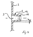
- FIG. 4 shows a cutout partial view of the hub region with a further possible embodiment.
- FIG. 1 shows a possible embodiment of a fan apparatus 1 according to the invention 1 .
- the fan apparatus 1 includes an impeller wheel 2 and a rotary drive 5 in the form of an electric motor.
- the impeller wheel 2 is driven by way of a drive shaft 4 of the rotary drive 5 which defines a rotary axis 3 .
- the impeller wheel 2 has a hub 6 , by way of which it is connected to the drive shaft 4 of the rotary drive 5 , with a nut 7 for fastening the impeller wheel 2 being screwed onto a thread 8 on the free end of the drive shaft 4 , as can be seen in particular from FIG. 3 .
- the impeller wheel 2 is pressed in the axial direction against a fixed attachment 9 fastened to the drive shaft 4 .
- the attachment 9 has several protrusions 10 arranged in a distributed fashion over the periphery, with these protrusions engaging in corresponding recesses 11 on the impeller wheel 2 .
- a conical flange 12 which runs approximately coaxially to the drive shaft 4 and tapers somewhat in the axial direction is provided, as can be seen in particular from FIG. 2 .
- the flange 12 forms a surface segment, which is assigned to an inner surface segment 13 of the nut 7 , as is shown in more detail in FIG. 3 .
- the conical flange 12 on the hub 6 of the impeller wheel 2 has a varying diameter, with the diameter reducing in the direction of the free end of the drive shaft 4 .
- the length of the flange 12 can amount to 2 mm in the axial direction for instance. Other dimensions are however also conceivable.
- the conical flange 12 preferably comprises an angle of inclination a in respect of the axis of rotation 3 of the drive shaft 4 between approximately 5° to 10°, in particular 7°.
- FIG. 3 shows the installed state of the impeller wheel 2 , in which the impeller wheel 2 is fixedly screwed to the drive shaft 4 with the nut 7 .
- This illustration shows that the inner surface segment 13 of the nut 7 and the assigned surface segment of the conical flange 12 on the hub 6 of the impeller wheel 2 press against one another so that a high surface pressure between the surface segments in realized. In this way, a particularly secure connection between the impeller wheel 2 and the drive shaft 4 can be realized with the fan facility 1 according to the invention.
- FIG. 4 shows an enlarged partial view of the hub 6 of the impeller wheel 2 with the molded flange 12 .
- This illustration shows the modular tapering flange 12 , the angle of inclination a of which in respect of the rotary axis 3 of the drive shaft amounts to approximately 7°, with the angle of inclination a being indicated by arrows in FIG. 4 .
- the free end of the conical flange 12 comprises a region 14 with a constant diameter, so that the free end of the flange 14 is embodied cylindrically. This allows the impeller wheel 2 to be assembled in a simpler fashion on the drive shaft 4 , without possibly running the risk of tilting being able to occur when the impeller wheel 2 is mounted.
Landscapes
- Engineering & Computer Science (AREA)
- Mechanical Engineering (AREA)
- General Engineering & Computer Science (AREA)
- Chemical & Material Sciences (AREA)
- Combustion & Propulsion (AREA)
- Structures Of Non-Positive Displacement Pumps (AREA)
Applications Claiming Priority (4)
| Application Number | Priority Date | Filing Date | Title |
|---|---|---|---|
| DE102005035462A DE102005035462A1 (de) | 2005-07-28 | 2005-07-28 | Gebläsevorrichtung für ein Gargerät |
| DE102005035462 | 2005-07-28 | ||
| DE102005035462.9 | 2005-07-28 | ||
| PCT/EP2006/063606 WO2007012535A1 (de) | 2005-07-28 | 2006-06-27 | Gebläsevorrichtung für ein gargerät |
Publications (2)
| Publication Number | Publication Date |
|---|---|
| US20090104037A1 US20090104037A1 (en) | 2009-04-23 |
| US8100656B2 true US8100656B2 (en) | 2012-01-24 |
Family
ID=36968868
Family Applications (1)
| Application Number | Title | Priority Date | Filing Date |
|---|---|---|---|
| US11/989,456 Expired - Fee Related US8100656B2 (en) | 2005-07-28 | 2006-06-27 | Fan apparatus for a cooking device |
Country Status (6)
| Country | Link |
|---|---|
| US (1) | US8100656B2 (de) |
| EP (1) | EP1913263B1 (de) |
| AT (1) | ATE497108T1 (de) |
| DE (2) | DE102005035462A1 (de) |
| ES (1) | ES2358126T3 (de) |
| WO (1) | WO2007012535A1 (de) |
Cited By (1)
| Publication number | Priority date | Publication date | Assignee | Title |
|---|---|---|---|---|
| US10982860B2 (en) * | 2015-09-21 | 2021-04-20 | Lg Electronics Inc. | Cooking device |
Families Citing this family (7)
| Publication number | Priority date | Publication date | Assignee | Title |
|---|---|---|---|---|
| DE102007016343B4 (de) | 2007-04-03 | 2017-03-30 | Miele & Cie. Kg | Befestigungseinrichtung für ein Gebläserad |
| US7958796B2 (en) * | 2008-11-12 | 2011-06-14 | Hiwin Technologies Corp. | Screw-driven fan device |
| DE102012217349A1 (de) | 2012-09-26 | 2014-03-27 | BSH Bosch und Siemens Hausgeräte GmbH | Lüftervorrichtung |
| WO2018087586A1 (en) * | 2016-11-14 | 2018-05-17 | Tecnome' S.R.L. | A centrifugal fan for high temperatures |
| CN106884806B (zh) * | 2017-04-27 | 2018-11-16 | 安徽江淮汽车集团股份有限公司 | 风扇总成 |
| IT201800002960A1 (it) * | 2018-02-22 | 2019-08-22 | Cebi Micromotors Switzerland S A | Gruppo ventola con sistema di aggancio ad innesto rapido. |
| CN110403488A (zh) * | 2019-05-06 | 2019-11-05 | 杭州为家美小家电有限公司 | 一种空气炸锅 |
Citations (9)
| Publication number | Priority date | Publication date | Assignee | Title |
|---|---|---|---|---|
| DE444597C (de) | 1924-11-07 | 1927-05-25 | Siemens Schuckertwerke G M B H | Verfahren zur Herstellung von Metallueberzuegen auf Metallelektroden fuer Quecksilberdampfgleichrichter |
| DE509460C (de) | 1930-10-09 | August Ottens | Befestigung des Laufrades bei Kreiselpumpen | |
| FR1129253A (fr) | 1955-07-27 | 1957-01-17 | Perfectionnements aux ventilateurs pour moteurs d'automobiles et analogues | |
| US3021049A (en) * | 1957-01-31 | 1962-02-13 | Gen Electric | Tapered clamping ring for fan and improved hub design |
| EP0468147A2 (de) | 1990-07-25 | 1992-01-29 | Alcatel SEL Aktiengesellschaft | Gebläse |
| DE4023874A1 (de) | 1990-07-27 | 1992-02-06 | Hochtemperatur Reaktorbau Gmbh | Absorberstab, der in eine schuettung kugelfoermiger brennelemente einfahrbar ist |
| US6305906B1 (en) | 1999-02-03 | 2001-10-23 | Itt Manufacturing Enterprises, Inc. | Device for attaching pump impeller |
| FR2816379A1 (fr) | 2000-11-08 | 2002-05-10 | Faurecia Ind | Ventilateur pour vehicule automobile et vehicule automobile correspondant |
| US20050287006A1 (en) * | 2004-06-29 | 2005-12-29 | Ingersoll-Rand Company | Device and method for detachably connecting an impeller to a shaft |
-
2005
- 2005-07-28 DE DE102005035462A patent/DE102005035462A1/de not_active Withdrawn
-
2006
- 2006-06-27 ES ES06763906T patent/ES2358126T3/es active Active
- 2006-06-27 US US11/989,456 patent/US8100656B2/en not_active Expired - Fee Related
- 2006-06-27 WO PCT/EP2006/063606 patent/WO2007012535A1/de not_active Ceased
- 2006-06-27 AT AT06763906T patent/ATE497108T1/de active
- 2006-06-27 DE DE502006008817T patent/DE502006008817D1/de active Active
- 2006-06-27 EP EP06763906A patent/EP1913263B1/de active Active
Patent Citations (9)
| Publication number | Priority date | Publication date | Assignee | Title |
|---|---|---|---|---|
| DE509460C (de) | 1930-10-09 | August Ottens | Befestigung des Laufrades bei Kreiselpumpen | |
| DE444597C (de) | 1924-11-07 | 1927-05-25 | Siemens Schuckertwerke G M B H | Verfahren zur Herstellung von Metallueberzuegen auf Metallelektroden fuer Quecksilberdampfgleichrichter |
| FR1129253A (fr) | 1955-07-27 | 1957-01-17 | Perfectionnements aux ventilateurs pour moteurs d'automobiles et analogues | |
| US3021049A (en) * | 1957-01-31 | 1962-02-13 | Gen Electric | Tapered clamping ring for fan and improved hub design |
| EP0468147A2 (de) | 1990-07-25 | 1992-01-29 | Alcatel SEL Aktiengesellschaft | Gebläse |
| DE4023874A1 (de) | 1990-07-27 | 1992-02-06 | Hochtemperatur Reaktorbau Gmbh | Absorberstab, der in eine schuettung kugelfoermiger brennelemente einfahrbar ist |
| US6305906B1 (en) | 1999-02-03 | 2001-10-23 | Itt Manufacturing Enterprises, Inc. | Device for attaching pump impeller |
| FR2816379A1 (fr) | 2000-11-08 | 2002-05-10 | Faurecia Ind | Ventilateur pour vehicule automobile et vehicule automobile correspondant |
| US20050287006A1 (en) * | 2004-06-29 | 2005-12-29 | Ingersoll-Rand Company | Device and method for detachably connecting an impeller to a shaft |
Non-Patent Citations (1)
| Title |
|---|
| International Search Report PCT/EP2006/063606. |
Cited By (2)
| Publication number | Priority date | Publication date | Assignee | Title |
|---|---|---|---|---|
| US10982860B2 (en) * | 2015-09-21 | 2021-04-20 | Lg Electronics Inc. | Cooking device |
| US12253265B2 (en) | 2015-09-21 | 2025-03-18 | Lg Electronics Inc. | Cooking device |
Also Published As
| Publication number | Publication date |
|---|---|
| EP1913263B1 (de) | 2011-01-26 |
| ATE497108T1 (de) | 2011-02-15 |
| DE502006008817D1 (de) | 2011-03-10 |
| EP1913263A1 (de) | 2008-04-23 |
| DE102005035462A1 (de) | 2007-02-01 |
| WO2007012535A1 (de) | 2007-02-01 |
| ES2358126T3 (es) | 2011-05-05 |
| US20090104037A1 (en) | 2009-04-23 |
Similar Documents
| Publication | Publication Date | Title |
|---|---|---|
| US8100656B2 (en) | Fan apparatus for a cooking device | |
| US11465671B2 (en) | Method for the production of electric power steering systems as well as an electric power steering system | |
| CN107664100A (zh) | 用于风力涡轮机的塔架的螺栓连接装置 | |
| CN104148571A (zh) | 盲铆接系统 | |
| CN100575711C (zh) | 真空泵装置 | |
| KR101223994B1 (ko) | 내연 기관의 캠축 조정 장치 및 장착용 공구 | |
| US20070140610A1 (en) | Bearing device for mounting of a high-speed rotor | |
| US10920830B2 (en) | Mixer comprising a clamping sleeve assembly | |
| US20140227029A1 (en) | Hollow shaft coupling | |
| JP4637101B2 (ja) | クランク軸装置及びクランク軸装置用の成形体 | |
| CN106255832B (zh) | 用于锁紧夹紧元件以防意外松动的装置 | |
| US7484813B2 (en) | Axle journal mounted to axle tube and method of assembly | |
| US6840139B2 (en) | Tapered installation tool | |
| CA2643150A1 (en) | Wheel hub with axial recesses between the holes for wheel bolts | |
| US20150357898A1 (en) | Electromagnetic coupling apparatus | |
| JP5860501B2 (ja) | 動力伝達装置 | |
| RU2402701C1 (ru) | Съемная ступица для монтажа вращающегося элемента на приводном валу | |
| CN113167315B (zh) | 用于调节轴承间隙的轴承组件和调节螺钉 | |
| CN116113775B (zh) | 连接系统、特别是轴装置 | |
| US9482387B2 (en) | Rotor machine having oil slinger system | |
| TWI873445B (zh) | 輪網系統及包含輪網系統之配置 | |
| RU2353832C1 (ru) | Стопорный болт землякова для сквозного резьбового отверстия | |
| US20230279939A1 (en) | Long-bolt power takeoff housing | |
| KR20140040888A (ko) | 차량 인휠 시스템의 모터 조립체 | |
| CN102349217A (zh) | 电机定子线圈的轴向压紧装置 |
Legal Events
| Date | Code | Title | Description |
|---|---|---|---|
| AS | Assignment |
Owner name: BSH BOSCH UND SIEMENS HAUSGERATE GMBH, GERMANY Free format text: ASSIGNMENT OF ASSIGNORS INTEREST;ASSIGNORS:KELLERMANN, PETER;LOHR, MARKUS-GUNTER;MALLINGER, PETER;AND OTHERS;REEL/FRAME:020446/0542 Effective date: 20080114 |
|
| STCF | Information on status: patent grant |
Free format text: PATENTED CASE |
|
| AS | Assignment |
Owner name: BSH HAUSGERAETE GMBH, GERMANY Free format text: CHANGE OF NAME;ASSIGNOR:BSH BOSCH UND SIEMENS HAUSGERAETE GMBH;REEL/FRAME:035624/0784 Effective date: 20150323 |
|
| AS | Assignment |
Owner name: BSH HAUSGERAETE GMBH, GERMANY Free format text: CORRECTIVE ASSIGNMENT TO REMOVE USSN 14373413; 29120436 AND 29429277 PREVIOUSLY RECORDED AT REEL: 035624 FRAME: 0784. ASSIGNOR(S) HEREBY CONFIRMS THE CHANGE OF NAME;ASSIGNOR:BSH BOSCH UND SIEMENS HAUSGERAETE GMBH;REEL/FRAME:036000/0848 Effective date: 20150323 |
|
| FPAY | Fee payment |
Year of fee payment: 4 |
|
| FEPP | Fee payment procedure |
Free format text: MAINTENANCE FEE REMINDER MAILED (ORIGINAL EVENT CODE: REM.); ENTITY STATUS OF PATENT OWNER: LARGE ENTITY |
|
| LAPS | Lapse for failure to pay maintenance fees |
Free format text: PATENT EXPIRED FOR FAILURE TO PAY MAINTENANCE FEES (ORIGINAL EVENT CODE: EXP.); ENTITY STATUS OF PATENT OWNER: LARGE ENTITY |
|
| STCH | Information on status: patent discontinuation |
Free format text: PATENT EXPIRED DUE TO NONPAYMENT OF MAINTENANCE FEES UNDER 37 CFR 1.362 |
|
| FP | Lapsed due to failure to pay maintenance fee |
Effective date: 20200124 |