US8109631B2 - Ophthalmic progressive addition lens with customized design feature - Google Patents
Ophthalmic progressive addition lens with customized design feature Download PDFInfo
- Publication number
- US8109631B2 US8109631B2 US12/524,210 US52421008A US8109631B2 US 8109631 B2 US8109631 B2 US 8109631B2 US 52421008 A US52421008 A US 52421008A US 8109631 B2 US8109631 B2 US 8109631B2
- Authority
- US
- United States
- Prior art keywords
- lens
- front face
- virtual lens
- vision
- target virtual
- Prior art date
- Legal status (The legal status is an assumption and is not a legal conclusion. Google has not performed a legal analysis and makes no representation as to the accuracy of the status listed.)
- Active, expires
Links
- 238000013461 design Methods 0.000 title claims abstract description 157
- 230000000750 progressive effect Effects 0.000 title claims abstract description 100
- 238000000034 method Methods 0.000 claims abstract description 68
- 230000003287 optical effect Effects 0.000 claims abstract description 66
- 238000004519 manufacturing process Methods 0.000 claims abstract description 19
- 238000004590 computer program Methods 0.000 claims abstract description 9
- 239000000758 substrate Substances 0.000 claims abstract description 7
- 230000004438 eyesight Effects 0.000 claims description 77
- 201000009310 astigmatism Diseases 0.000 claims description 62
- 208000001491 myopia Diseases 0.000 claims description 48
- 230000009466 transformation Effects 0.000 claims description 41
- 238000012937 correction Methods 0.000 claims description 36
- 238000009826 distribution Methods 0.000 claims description 36
- 230000007547 defect Effects 0.000 claims description 32
- 238000004364 calculation method Methods 0.000 claims description 21
- 238000005457 optimization Methods 0.000 claims description 20
- 238000003754 machining Methods 0.000 claims description 8
- 230000004075 alteration Effects 0.000 claims description 5
- 230000006870 function Effects 0.000 description 35
- 210000001508 eye Anatomy 0.000 description 11
- 210000000887 face Anatomy 0.000 description 10
- 210000001747 pupil Anatomy 0.000 description 10
- 238000013519 translation Methods 0.000 description 8
- 238000005520 cutting process Methods 0.000 description 7
- 238000010586 diagram Methods 0.000 description 7
- 230000015654 memory Effects 0.000 description 6
- 230000006835 compression Effects 0.000 description 5
- 238000007906 compression Methods 0.000 description 5
- 210000003128 head Anatomy 0.000 description 5
- 238000005259 measurement Methods 0.000 description 5
- 230000006872 improvement Effects 0.000 description 4
- 230000008447 perception Effects 0.000 description 4
- 230000008901 benefit Effects 0.000 description 3
- 238000000576 coating method Methods 0.000 description 3
- 230000000694 effects Effects 0.000 description 3
- 239000011521 glass Substances 0.000 description 3
- 230000005043 peripheral vision Effects 0.000 description 3
- 230000008569 process Effects 0.000 description 3
- 230000002123 temporal effect Effects 0.000 description 3
- 238000004458 analytical method Methods 0.000 description 2
- 230000006399 behavior Effects 0.000 description 2
- 230000004424 eye movement Effects 0.000 description 2
- 230000004886 head movement Effects 0.000 description 2
- 239000000463 material Substances 0.000 description 2
- 238000007620 mathematical function Methods 0.000 description 2
- 239000000203 mixture Substances 0.000 description 2
- 230000009467 reduction Effects 0.000 description 2
- 238000003860 storage Methods 0.000 description 2
- 230000000007 visual effect Effects 0.000 description 2
- 208000029091 Refraction disease Diseases 0.000 description 1
- 230000009471 action Effects 0.000 description 1
- 230000006978 adaptation Effects 0.000 description 1
- 230000004430 ametropia Effects 0.000 description 1
- 239000006117 anti-reflective coating Substances 0.000 description 1
- 230000005540 biological transmission Effects 0.000 description 1
- 238000006243 chemical reaction Methods 0.000 description 1
- 239000011248 coating agent Substances 0.000 description 1
- 210000004087 cornea Anatomy 0.000 description 1
- 230000001627 detrimental effect Effects 0.000 description 1
- 230000009977 dual effect Effects 0.000 description 1
- 230000003203 everyday effect Effects 0.000 description 1
- 210000000744 eyelid Anatomy 0.000 description 1
- 230000005669 field effect Effects 0.000 description 1
- 230000004927 fusion Effects 0.000 description 1
- 238000003780 insertion Methods 0.000 description 1
- 230000037431 insertion Effects 0.000 description 1
- 238000012986 modification Methods 0.000 description 1
- 230000004048 modification Effects 0.000 description 1
- 238000000465 moulding Methods 0.000 description 1
- 210000004279 orbit Anatomy 0.000 description 1
- 230000035790 physiological processes and functions Effects 0.000 description 1
- 201000010041 presbyopia Diseases 0.000 description 1
- 238000004321 preservation Methods 0.000 description 1
- 208000014733 refractive error Diseases 0.000 description 1
- 239000005871 repellent Substances 0.000 description 1
- 210000001525 retina Anatomy 0.000 description 1
- 230000002207 retinal effect Effects 0.000 description 1
- 239000006120 scratch resistant coating Substances 0.000 description 1
- 230000005477 standard model Effects 0.000 description 1
- 238000012549 training Methods 0.000 description 1
- 238000000844 transformation Methods 0.000 description 1
- 230000004382 visual function Effects 0.000 description 1
Images




Classifications
-
- G—PHYSICS
- G02—OPTICS
- G02C—SPECTACLES; SUNGLASSES OR GOGGLES INSOFAR AS THEY HAVE THE SAME FEATURES AS SPECTACLES; CONTACT LENSES
- G02C7/00—Optical parts
- G02C7/02—Lenses; Lens systems ; Methods of designing lenses
- G02C7/06—Lenses; Lens systems ; Methods of designing lenses bifocal; multifocal ; progressive
- G02C7/061—Spectacle lenses with progressively varying focal power
- G02C7/063—Shape of the progressive surface
- G02C7/065—Properties on the principal line
-
- B—PERFORMING OPERATIONS; TRANSPORTING
- B29—WORKING OF PLASTICS; WORKING OF SUBSTANCES IN A PLASTIC STATE IN GENERAL
- B29D—PRODUCING PARTICULAR ARTICLES FROM PLASTICS OR FROM SUBSTANCES IN A PLASTIC STATE
- B29D11/00—Producing optical elements, e.g. lenses or prisms
- B29D11/00009—Production of simple or compound lenses
- B29D11/00028—Bifocal lenses; Multifocal lenses
-
- G—PHYSICS
- G02—OPTICS
- G02C—SPECTACLES; SUNGLASSES OR GOGGLES INSOFAR AS THEY HAVE THE SAME FEATURES AS SPECTACLES; CONTACT LENSES
- G02C7/00—Optical parts
- G02C7/02—Lenses; Lens systems ; Methods of designing lenses
-
- G—PHYSICS
- G02—OPTICS
- G02C—SPECTACLES; SUNGLASSES OR GOGGLES INSOFAR AS THEY HAVE THE SAME FEATURES AS SPECTACLES; CONTACT LENSES
- G02C7/00—Optical parts
- G02C7/02—Lenses; Lens systems ; Methods of designing lenses
- G02C7/024—Methods of designing ophthalmic lenses
- G02C7/028—Special mathematical design techniques
Definitions
- the present invention relates to a method for manufacturing an ophthalmic progressive addition lens with customized design feature(s), and also to a method for the determination of a customized ophthalmic progressive addition lens.
- An ophthalmic progressive addition lens or PAL
- the meridian line connects a distance-vision point on the lens, to which the optical power and astigmatism of the lens are adapted in order to correct the distance vision of a wearer, to a near-vision point to which the optical power is adapted in order to correct the near vision of the wearer.
- a method for vision correction traditionally includes measuring optical aberration data of a wearer's eye, usually performed by optometrists or ophthalmologists, determining the lens parameters and offering to the wearer a plurality of model lenses with different lens “designs”.
- the wearer's vision parameters are measured using for example trial lenses, an aberrometer, a wave-front sensor, grating or other known method and/or apparatus.
- vision parameters can be obtained such as the wearer's vertex distance, pupil size, pupil distance, frame information, gaze directions.
- the optical surface or “design” imparts the optical correction of the material. Given the infinite number of eyesight corrections, the numbers of designs is almost infinite.
- PAL have gained worldwide acceptance as the most performant ophthalmic lenses for correction of presbyopia because they provide comfortable vision at all distances.
- a PAL is designed not only to restore a presbyope's ability to see clearly at all distances but also to optimally respect all physiological visual functions, in particular:
- the optometrist or ophthalmologist proposes usually a lens “model design” that may be the result of an analysis of the viewing behavior of the wearer.
- an ophthalmic lens which is adapted to the vision of a wearer is obtained starting from a semi-finished lens with the chosen “model design” which is manufactured in large volume, and which has a finished front face.
- the front face of the semi-finished lens has local values of average sphere and of cylinder that vary between different points of this face.
- the rear face, also called back face, of the semi-finished lens is used to adapt the ophthalmic correction to the ametropia of the wearer. For this purpose, it is re-machined according to a prescription established for the wearer.
- the rear face of the final lens is usually of simple shape: it has uniform values of average sphere and of cylinder which, in combination with the front face, give the lens optical characteristics that conform to the prescription.
- the rear face may also comprise a progressive addition surface so as the lens is called a “dual add” PAL.
- the semi-finished lens is selected from amongst several standard models (based on the “model design”) as a function of a curvature value of the front face at the distance-vision point and from an addition value.
- the front face of a progressive semi-finished lens has fixed design features values, which are also called standard designs features values. They are determined for average conditions of use of the lens and are fixed when the semi-finished lens is moulded.
- the principal standard design features are selected in the list consisting of the standard size parameters of the different vision zones of the progressive addition lens (such as for example the near vision zone, the intermediate vision zone, the distance vision zone), standard inset of a wearer, standard frame design parameters, standard viewing preferences.
- the size of the distance vision zone is greater than the size of the near vision zone, which is greater than the size of the intermediate zone.
- the near-vision point can be shifted horizontally with respect to a vertical line passing through the distance-vision point, when the lens is in a position of use by its wearer.
- This shift which is in the direction of the nasal side of the lens, is usually referred to as “inset”. It depends on the optical power of the lens, on the variation in convergence of the view of the wearer between his distance vision and near vision, on the distance of observation of an object, on the prismatic deviation of the lens and on the eye-lens distance, notably.
- FIG. 1 a indicates the positions of the distance-vision and near-vision points of an ophthalmic lens 100 , respectively denoted VL and VP, the mounting cross, denoted CM, the meridian line, denoted LM, and the inset, denoted In.
- FIG. 1 b is a profile view of the lens 100 , showing the front face of the latter, which is convex and referenced S 0 , and its concave rear face S 1 .
- the design feature parameter is the inset
- this can be achieved by simply rotating the semi-finished lens about its optical axis, before the rear face has been adjusted to the prescription and before the lens is cut to the dimensions of a frame of a pair of glasses.
- the inset value can thus be customized, by means of the angle of rotation, as a function of the measurements made on the wearer. But then all the characteristics of the lens, including the variations in astigmatism outside of the distance-vision and near-vision regions, are simultaneously rotated. This results notably in a reduction in the width of the distance-vision region, measured in a horizontal direction, which may be detrimental to the comfort of the wearer.
- One goal of the present invention therefore consists in providing a method for manufacturing a progressive addition lens with customized design feature(s), which does not have the drawbacks mentioned hereinabove.
- Another goal consists in providing a method that is compatible with the manufacturing of a correction lens starting from a substrate, such as for example semi-finished progressive lens, whose front face is not modified by re-working.
- one subject of the invention is a method for manufacturing an ophthalmic progressive addition lens with customized design feature(s) adapted to a wearer, the method comprising the following steps:
- the rear face of the lens is used both for obtaining the prescription and for modifying the apparent value of the design feature of the lens, with respect to the standard design feature value of the front face of the lens.
- the rear face can for example therefore be used in order to customize the design feature of the lens. For this reason, it has a shape that is generally complex. In other words, the values of average sphere and of cylinder of the rear face vary between different points of the latter.
- the front face of the semi-finished lens can then not be modified by re-working in order to form the finished lens with customized design feature, in a method according to the invention.
- the customization of the design feature of progressive addition lenses does not require the number of models of progressive semi-finished lenses to be increased, with respect to a range of semi-finished lenses which are defined by their curvature values and their addition values.
- the shape of the rear face of the lens that has to be manufactured is determined by digital optimization. Such a determination can be carried out simply and quickly, by using simple computer means that are widely available, such as a personal computer.
- the wearer's viewing preferences are chosen in the list consisting of maximizing the distance viewing comfort, maximizing the intermediate viewing comfort, maximizing the near viewing comfort.
- the ophthalmic progressive addition lens ( 100 ) comprises:
- step /b/ itself comprises the following two sub-steps:
- step /b/ itself comprises the following sub-steps:
- step /b/ itself comprises the following sub-steps:
- one of the two reference front faces obtained in step /b1′′/ is the front face of the semi-finished lens (S 0 ) obtained in step /a/.
- the method comprises following steps:
- the stage of measuring parameters representing the frame comprises the stages of:
- applying the transformation coefficients calculated ( ⁇ , ⁇ ) to the spherical coordinates ( ⁇ , ⁇ ) consists in multiplying the horizontal angular value ( ⁇ ) by the horizontal coefficient ( ⁇ ) and multiplying the vertical angular value ( ⁇ ) by the vertical coefficient ( ⁇ ).
- calculating the personalized distribution of the targets is carried out whilst maintaining constant the ratio of the area of the lens surface for which the resulting astigmatism defect is less than or equal to 0.5 diopters over the total surface of the cut-out lens.
- the invention relates also to a method for the determination of a customized ophthalmic progressive addition lens with customized design features, with the provision that the design feature is not a frame design parameter, comprising:
- features of the here above mentioned method for manufacturing an ophthalmic progressive addition lens may be features of the present method for the determination a customized ophthalmic progressive addition lens, with the provision that said features are not specific of design features of a frame.
- the invention also relates to a computer program product comprising one or more stored sequences of instructions that is accessible to a processor and which, when executed by the processor, causes the processor to carry out at least one of the steps of the different embodiments of the preceding methods.
- the invention also relates to a computer-readable medium carrying one or more sequences of instructions of the preceding computer program product.
- Embodiments of the present invention may include apparatuses for performing the operations herein.
- This apparatus may be specially constructed for the desired purposes, or it may comprise a general purpose computer or Digital Signal Processor (“DSP”) selectively activated or reconfigured by a computer program stored in the computer.
- DSP Digital Signal Processor
- Such a computer program may be stored in a computer readable storage medium, such as, but is not limited to, any type of disk including floppy disks, optical disks, CD-ROMs, magnetic-optical disks, read-only memories (ROMs), random access memories (RAMs) electrically programmable read-only memories (EPROMs), electrically erasable and programmable read only memories (EEPROMs), magnetic or optical cards, or any other type of media suitable for storing electronic instructions, and capable of being coupled to a computer system bus.
- a computer readable storage medium such as, but is not limited to, any type of disk including floppy disks, optical disks, CD-ROMs, magnetic-optical disks, read-only memories (ROMs), random access memories (RAMs) electrically programmable read-only memories (EPROMs), electrically erasable and programmable read only memories (EEPROMs), magnetic or optical cards, or any other type of media suitable for storing electronic instructions, and capable of being coupled to a computer system bus.
- FIGS. 1 a and 1 b are plan and profile views, respectively, of an ophthalmic progressive addition lens, which indicates certain geometrical or optical data on this lens;
- FIG. 1 c illustrates the principle of a shear function
- FIG. 2 a is a flow diagram of the use of geometrical data which corresponds to a first embodiment of the invention
- FIGS. 2 b - 2 g are contour maps relating to a progressive addition lens with a customized design feature, which is the inset in the present example, manufactured using a method according to the embodiment in FIG. 2 a;
- FIGS. 3 a and 4 a correspond to FIG. 2 a , for a second and third embodiment of the invention, respectively;
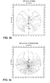
- FIGS. 3 b - 3 k are contour maps relating to a progressive addition lens with a design feature, which is the inset in the present example, manufactured using a method according to the embodiment in FIG. 3 a;
- FIGS. 4 b - 4 i are contour maps relating to a progressive addition lens with a design feature, which is the inset in the present example, manufactured using a method according to the embodiment in FIG. 4 a;
- FIGS. 5 a - 5 b are contour maps relating to a progressive addition lens with customized inset, manufactured using a method known from the prior art
- FIG. 6 is a diagram of an ordinary frame
- FIG. 7 is a diagram of a lens before and after cutting out for insertion into a frame of FIG. 6 ;
- FIGS. 8 a and 8 b are maps of resulting astigmatism for a lens of the prior art and for a lens according to an embodiment of the invention respectively;
- FIGS. 9 a and 9 b are maps of resulting astigmatism for a lens of the prior art and for a lens according to an other embodiment of the invention respectively;
- FIGS. 10 a and 10 b are maps of resulting astigmatism for a lens of the prior art and for a lens according to an other embodiment of the invention respectively;
- FIGS. 11 and 12 are diagrammatic views of flow diagrams of the use of geometrical data which correspond to another embodiment of the invention.
- FIG. 1 a shows schematically an addition lens 100 , before the latter has been cut out around a contour C to the dimensions of a frame recess of a pair of glasses.
- the nasal and temporal sides of the lens respectively denoted N and T
- the meridian line LM the distance-vision and near-vision points
- VL and VP the distance-vision and near-vision points
- O an optical centre of the lens
- FIG. 1 b shows the front and rear faces of the lens 100 , respectively denoted S 0 and S 1 , together with the optical axis of the lens, denoted Z.
- the lens 100 is a semi-finished lens
- this can be chosen from amongst a range of 60 models for example, which consists of five available values for the curvature of the front face at the distance-vision point, and for each of these values of curvature, of twelve available values for the addition.
- Each semi-finished lens in this range has a standard inset value, which is fixed for the corresponding model. It also has his other own standard design features.
- a semi-finished lens is selected from one of the models available in the range, starting from which the final lens will be manufactured.
- This manufacturing consists in a re-work by machining of the rear face of the lens, where required the application of functional coatings on the faces of the lens, and the cutting out of the lens.
- the functional coatings can be, without limitation, an antireflective coating, a scratch-resistant coating, a dirt-repellent coating, etc., or a combination of these.
- the supply of the semi-finished lens as a function of the prescription of the wearer corresponds to the first line of FIGS. 2 a , 3 a and 4 a .
- the front face S 0 of the lens 100 is thus known.
- the aim of the manufacturing of the lens which is now described consists in determining and in machining the rear face S 1 of the lens 100 , in order to obtain the ametropic correction prescribed for the wearer, together with a customized design feature value for the latter.
- the customized design feature value can be determined from measurements that are carried out on the wearer.
- Determinable customized design feature value are for example the inset of the wearer that relate for example to the distance between the apex of the cornea and the lens for the chosen frame, the variation in the convergence of the gaze for objects which are observed at variable distance, the reading distance, etc, or the customized design feature that can relate to another specific need of the wearer.
- FIGS. 2 a , 3 a and 4 a surface data corresponding to the same face of the lens 100 are indicated in columns, so as to allow easier displaying of the corresponding implementations.
- Said surface data are defined or calculated with standard design features, using standard design features parameters.
- the vertical arrows indicate the variation or the use of these data values for each implementation.
- Each row displays the surface data of the real lens or of a virtual lens that corresponds to one step of the method. This lens is indicated at the beginning of the row or at the end of it, according to whether it is a real lens (semi-finished lens or finished lens) or a virtual lens.
- a virtual lens is a lens whose front and rear faces are numerically defined, and which is used to perform optical or surface calculations or which results from such calculations.
- step /b/ of the method of the invention which consists in defining the target virtual lens, itself comprises the two following sub-steps:
- the rear face of the lens is then machined according to a virtual lens, which is optimized so as to have both the customized design feature value, determined for the wearer, and the ametropic correction prescribed for him.
- a virtual lens which is optimized so as to have both the customized design feature value, determined for the wearer, and the ametropic correction prescribed for him.
- such an optimization is performed digitally starting from a target virtual lens, in such a manner as to arrive at the distributions of the optical quantities, such as the optical power and the astigmatism.
- Programmes designed to carry out such optimizations are assumed to be known to those skilled in the art and are not described here.
- the target virtual lens is determined in two successive steps.
- the virtual lens is generated digitally, with the front face of the semi-finished lens and a simple rear face that corresponds to the prescription.
- a simple face refers to a face with values of average sphere and of cylinder that are constant between any two points of the latter.
- the rear face of the intermediate virtual lens is therefore selected in the manner generally practiced for a progressive lens prior to the present invention.
- the front face of the intermediate virtual lens is identical to that of the semi-finished lens.
- the intermediate virtual lens therefore has an apparent design feature value which is equal to the standard design feature value of the front face of the semi-finished lens.
- the target virtual lens is then defined from the intermediate virtual lens, in such a manner as to have an apparent design feature value which is equal to the customized design feature value determined for the wearer.
- a shear function is digitally applied to the optical characteristics of the intermediate virtual lens, over all or part of the surface of the latter. This shear function is selected in such a manner as to transform the design feature value of the intermediate virtual lens into the customized design feature value.
- a shear function is understood to mean a translation of the optical properties of the lens, with respect to a fixed coordinate system that is associated with the lens, whose translation amplitude varies along a direction perpendicular to the direction of translation.
- the optimization can be carried out by using a trial virtual lens which is modified at each iteration of the optimization process.
- This trial virtual lens has a fixed front face which is identical to that of the semi-finished lens, and a rear face which is variable.
- a simple rear face, which corresponds to the prescription established for the wearer, can be adopted as initial rear face of the trial virtual lens.
- the trial virtual lens is then optimized with respect to the optical characteristics of the target virtual lens.
- This optimization transforms the rear face of the trial virtual lens in such a manner that the latter performs a conversion of the apparent design feature value of the lens.
- the value that is finally obtained is close to the customized design feature value determined for the wearer.
- the wording “close” is used to characterize a difference between two values that is equal or less than a given threshold; such a threshold can be introduced as an optimisation parameter.
- the geometry of the rear face of the virtual lens thus optimized is denoted RESULT in FIG. 2 a.
- the rear face S 1 of the semi-finished lens 100 is then machined according to this data, for example using a three-axis machining tool.
- FIGS. 1 c , 2 b to 2 g relates to embodiments where the inset is the design feature to be customized.
- FIG. 1 c illustrates the transformation of the meridian line of the intermediate virtual lens, denoted LM 0 , into a meridian line of the target virtual lens, denoted LM 1 .
- the horizontal arrows that connect LM 0 to LM 1 correspond to the length of the translation at different heights on the lens.
- the direction of translation is parallel to the direction X indicated in FIG. 1 c , and the translation length varies in the direction Y.
- the translation length which can be zero above the distance-vision point VL, varies between VL and the near-vision point VP, and can be constant below VP.
- In 0 and In 1 indicate the inset values before and after the application of the shear function.
- the shear function is defined in two successive parts, one above the mounting cross CM and which corresponds to no shear, the other below the mounting cross CM and which corresponds to a variable shear.
- FIGS. 2 b and 2 c are optical analyses of the lens carried out for the optical power and for the resulting astigmatism, respectively.
- the ordinate and abscissa coordinates correspond to the angles of the viewing direction of the wearer with the optical axis Z of the lens 100 , in a horizontal and vertical plane, respectively. These two angles are denoted by alpha and beta and expressed in degrees.
- the curves indicated are iso-power curves, identified in diopters by the difference with respect to the power value at the distance-vision point VL.
- the curves indicated correspond to points for which the value of astigmatism is constant, identified in diopters by the difference with respect to the prescribed value.
- the astigmatism that appears in this figure is called resulting astigmatism and is substantially equal to zero along the trace that corresponds to the meridian line.
- the crosses that are indicated in these figures correspond to the viewing directions which respectively pass through the distance-vision points VL, through the mounting cross of the lens CM, and through the near-vision point VP.
- the final lens in FIGS. 2 b and 2 c has been obtained starting from a semi-finished lens, whose front face S 0 has a base value of 5.0, an addition of 2.0 diopters and a standard inset value of 2.5 mm (millimetres).
- the prescription for this lens is a correction of zero for the distance vision and an addition of 2.0 diopters.
- Its rear face S 1 has been machined to give the lens an apparent inset value of 5 mm, corresponding to a horizontal angular shift of 11 degrees with respect to the distance-vision direction.
- FIGS. 2 d and 2 e are contour maps of the optical power and of the resulting astigmatism of the semi-finished lens that has been used, when it is machined with a spherical rear face.
- the horizontal angular shift of the viewing direction for the near vision, with respect to the viewing direction for the distance vision, is 6 degrees in these figures, corresponding to the standard inset of 2.5 mm.
- the machining of the rear face 51 has therefore made it possible to obtain an apparent inset of 5 mm starting from a standard inset of 2.5 mm.
- FIGS. 2 f and 2 g are contour maps of the values of average sphere and of cylinder of the rear face S 1 of the final lens, which has been machined according to the optimized trial virtual lens.
- the coordinates on the lens are marked out in millimetres along the axes X and Y, for the horizontal and vertical directions, respectively.
- the curves of average iso-sphere and of iso-cylinder respectively correspond to the values of 0.25 diopters (average sphere for FIG. 2 f ) and 0.25/0.50 diopters (cylinder for FIG. 2 g ).
- FIGS. 5 a and 5 b are contour maps of optical power and resulting astigmatism for a progressive addition lens that has the same front face as the lens in FIGS. 2 b - 2 g , and a simple rear face that corresponds to the prescription.
- the apparent inset value of 5 mm has been obtained by simply rotating the lens about its optical axis Z.
- FIGS. 2 b and 5 a together with that between FIGS. 2 c and 5 b , shows that the invention allows distance- and near-vision regions to be obtained that are distributed more symmetrically with respect to vertical planes passing through the distance-vision and near-vision points.
- step /b/ of the method of the invention which consists in defining the target virtual lens, itself comprises the following three sub-steps:
- the target virtual lens is then formed by this optimized front face, which is combined with a simple rear face corresponding to the prescription.
- the optimization of the trial virtual lens, with respect to the optical characteristics of the target virtual lens is then identical to that described for the first embodiment of the invention.
- the rear face of the lens which is obtained as a result of the optimization of the trial virtual lens, according to the second embodiment of the invention, can still be produced.
- FIGS. 3 b - 3 g illustrate this second embodiment of the invention, where the inset is the design feature to be customized, in the same manner as in FIGS. 2 b - 2 g for the first embodiment:
- the prescription for the lens corresponds to an optical power of +2.0 diopters in distance vision, without correction for astigmatism.
- the rear face S 0 of the semi-finished lens has the following characteristics: base of 6.0, addition equal to 2.5 diopters and standard inset of 3.3 mm, corresponding to a horizontal angular shift of the direction of near vision of 7 degrees.
- the rear face S 1 has been determined in such a manner as to obtain an apparent inset value of 0 mm, corresponding to a viewing direction for the near vision which is situated in the same vertical plane as for the distance vision.
- FIGS. 3 h and 3 i are contour maps of the average sphere and of cylinder of the front face of the target virtual lens, obtained after the optimization of the surface characteristics of the front face with customized inset value.
- step /b/ of the method of the invention itself comprises the following three sub-steps:
- This third embodiment of the invention differs from the second in the manner of generating digitally the front face of the target virtual lens.
- this front face is obtained by mixing two reference faces that have different design feature values.
- such a mixing can be performed by characterizing each face by its sagittal values at the points of a common mesh defined on the latter.
- the sagittal values of the two reference faces are then added together, for each point of the mesh, weighting them by weighting coefficients that are adapted so that the resulting front face has the customized design feature value.
- the two reference faces can each correspond to the addition value that is prescribed for the wearer, or each have an addition value that is close to that prescribed.
- the sum of the two weighting coefficients that are respectively assigned to the two reference faces, for the same point of the mesh, can be equal to unity. These coefficients could also vary between different points of the mesh, in order to modify the importance of one of the two reference faces in the mixture, in certain regions of the front face of the lens.
- one of the two front reference faces which is obtained at step /b1′′/ can be the front face S 0 of the semi-finished lens which is obtained at step /a/.
- the other front reference face can then have an design feature value that is higher or lower than the front face of the semi-finished lens, depending on the customized design feature value that has been determined for the wearer.
- FIGS. 4 b - 4 g illustrate this third embodiment of the invention where the inset is the design feature to be customized, again in the same manner as FIGS. 2 b - 2 g for the first embodiment.
- the prescription of the lens corresponds to an optical power of +4.0 diopters for distance vision, without correction for astigmatism.
- the front face of the semi-finished lens has the following characteristics: base of 7.25, addition equal to 1.5 diopters and standard inset of 3.0 mm, corresponding to a horizontal angular shift in the near-vision direction of 6.5 degrees.
- the rear face S 1 has been determined in such a manner as to obtain an apparent inset value of 0 mm, corresponding to a viewing direction for the near vision that is situated in the same vertical plane as the viewing direction for the distance vision.
- the mixed front face has been obtained by mixing two reference front faces of base 7.25 and of addition 1.5 diopters, having respective inset values of 3.0 mm and 0.0 mm, so as to obtain a resulting surface of inset 1.0 mm.
- the coefficients of the mixture are respectively 1 ⁇ 3 and 2 ⁇ 3.
- FIGS. 4 h and 4 i are contour maps of average sphere and of cylinder of the front face of the target virtual lens after the mixing of the reference faces.
- the target virtual lens can be defined with a base value of the front face different from the base value which would be selected for the semi-finished lens, depending on the vision correction prescribed. In this way, optical aberrations of the final addition lens can be minimized.
- the optimization of the trial virtual lens with respect to the target virtual lens can be carried out by initially assigning to the trial virtual lens a rear face which is the result of a subtraction between the front face of the semi-finished lens S 0 and the front face of the target virtual lens, with respect to the uniform values of average sphere and of cylinder. In this way, the optimization is faster.
- a subtraction of surfaces denotes an operation for the combination of two initial surfaces so as to obtain a third from them, by which a sagittal value (or ‘sag value’) of the second surface is subtracted from that of the first surface, at each point of a projection of the surfaces onto a base plane, and the third surface is defined by assigning the result of the subtraction as a new sag height at the same point.
- a sagittal value or ‘sag value’
- the optimization requires a smaller number of iterations to achieve the same value for the merit function.
- FIGS. 3 j and 3 k are initial contour maps of average sphere and of cylinder of the initial rear face of the trial virtual lens, thus determined.
- Embodiments of the present invention propose taking into account the shape and the size of the frame in order to retain the distribution between the far-vision, near-vision and intermediate-vision zones on the lens and are described in view of FIGS. 6 to 10 .
- a given design of a progressive ophthalmic lens is used, a spatial transformation is applied which retains the power and resulting astigmatism defect values but shifts these values on the surface of the lens in order to spread or close up the power and astigmatism gradients.
- the gradients can be closed up in order to guarantee the presence of a minimum surface of the near-vision zone and in the case of a large frame, the gradients can be spread in order to clear the vision fields and in order to improve peripheral vision.
- the present embodiment of the invention proposes a method for manufacturing a progressive ophthalmic lens for a presbyopic wearer, i.e. for whom a power addition (Add) has been prescribed for near vision.
- the embodiments of the invention makes it possible to manufacture a progressive ophthalmic lens guaranteeing for the wearer good accessibility to the near-vision zone and an improved dynamic vision in the entire vision field whatever the type of frame chosen and its prescription.
- a progressive lens has a far-vision zone with a control point FV, a near-vision zone with a control point NV and an intermediate-vision zone.
- the lens has a substantially umbilical line, called a principal progression meridian crossing these three zones, over which the astigmatism is practically nil.
- the meridian coincides with the vertical axis in the upper part of the lens and can have an inclination on the nose side in the lower part of the lens, the convergence being more marked in near vision.
- the lateral shift of the control point NV relative to the vertical axis of the meridian in the upper part of the lens is called an inset.
- the meridian therefore has a power progression between the control point in far vision FV and the control point in near vision NV; this progression corresponds approximately to the value of the addition prescribed.
- a fitting cross CM is marked by a reference point on the complex surface and constitutes an aid for fitting the cut-out lens into the frame; this fitting cross CM makes it possible to locate on the lens the primary direction of viewing under wearing conditions.
- progression length PL refers to the vertical distance between the fitting cross CM and the point of the meridian in near vision NV at which the power progression reaches the prescribed power.
- the progression length PL defines the accessibility to the powers necessary in near vision.
- the profile of the meridian represents the wearer power as a function of lowering the eyes in the eye sockets with a direction of viewing which is straight ahead.
- the wearer will have to lower his eyes more or less in order to be able to take full advantage of the near-vision zone.
- the near-vision zone can be substantially present on the cut-out lens depending on the size and the shape of the frame.
- an initial design of a progressive lens is chosen.
- This design establishes an initial distribution of power and resulting astigmatism defect targets for each direction of viewing under wearing conditions in a standard size frame.
- the design chosen can correspond to any design of a known or future progressive lens, for example the initial distribution of the power and resulting astigmatism defect targets can correspond to a Varilux Comfort® or Varilux Panamic® lens.
- FIG. 6 shows a diagram of a frame and FIG. 7 diagrammatically illustrates a lens before and after cutting out.
- FIG. 6 shows a representation of a frame and the position of the right and left pupils of the wearer in the frame, which are respectively referenced D and G.
- the figure shows for the frame the contour of the lens in thick lines, and in thin lines the internal and external limits of the frame.
- the template is therefore the external shape that the lens must have once cut out in order to fit in the frame.
- the letter B designates the total height of the template determined with the Boxing system, i.e. according to the IS08624 standard on systems for the measurement of lenses frames.
- This height corresponds to the height of a rectangle into which the lens fits once it is cut out. In the case of a drilled frame, without any template, it is the height B of the cut-out lens ( FIG. 7 ) which is considered.
- An element connecting the right and left templates of the frame is called the bridge of the frame, referenced by letter P in FIG. 6 .
- the bridge P can also be a rod connecting drilled right and left lenses.
- Interpupillary distance EP refers to the distance between the two pupils of the wearer.
- an optician measures the right interpupillary half-distance and the left interpupillary half-distance, which are referenced PD and PG.
- the left half-distance (respectively right) is the distance between the vertical axis of symmetry of the frame and the centre of the left pupil (respectively right).
- Right boxing height HD (respectively left boxing height HG) refers to the vertical distance between the right pupil (respectively left) and the lowest point of the right half-frame (respectively left height).
- the optician measures the DATUM heights referenced HDd and HGd in FIG. 6 .
- These right and left reference heights are respectively the distances between the right or left pupil and the right or left intersection between a vertical line passing through the pupil and the frame in its lower part.
- the measurements of interpupillary distance and of height of the pupil relative to the frame are carried out for a given position of the wearer, namely for the wearer looking at infinity with his head straight.
- the features of a given frame can be measured on the frame, using a device known per se.
- U.S. Pat. No. 5,333,412 describes a device which makes it possible to measure in 3-dimensions, the shape of the bottom of the groove of the frame. The shape thus determined then makes it possible to calculate the height B.
- the features of a frame can also be given directly by the manufacturer according to the model chosen by the wearer.
- each lens is cut out such that the fitting cross CM is situated in the frame facing the pupil of the corresponding eye, when the wearer looks at infinity with his head straight. Consequently, when the wearer of the frame looks at infinity with his head straight, his viewing passes through the lens at the fitting cross. It is of course possible, if the fitting cross is not marked on the lens, to use the medium of the micro-marks for positioning the lenses, after correction by the distance between this medium and the fitting cross.
- FIG. 7 shows a representation of the contour of an ophthalmic lens, before and after cutting out.
- the thin line corresponds to the contour of the lens before cutting out; in a standard manner, the lens can be obtained by moulding and has a circular shape.
- the thick line corresponds to the contour of the template of the frame, which is also the contour of the lens after cutting out the lens. This cutting out of the lens allows the subsequent fitting of the lens in the frame.
- FIG. 7 shows the total width A of the template of the frame and the total height B of this template, i.e. the width and the height of the rectangle into which the cut-out lens fits.
- the positioning of the lens in the frame consists in determining the desired position of the lens in the frame, using notable points of the lens.
- the fitting cross of the lens, the medium of micro-marks marked on the surface of the lens, or also the optical centre in the case of a unifocal lens can be used.
- the fitting cross is marked by the cross referenced CM.
- a given frame, chosen by a given wearer can thus be characterized by a certain number of parameters representing its size and its shape.
- a vertical parameter, referenced B′ depending on the fitting height measured HD, HG or HDd, HGd according to the measurement system chosen.
- vertical parameter B′ the measured variable HD (HG).
- standard parameters are defined as the average value of the horizontal and vertical parameters as defined above for a representative sample of frames and for the average of wearers.
- a standard vertical parameter B′av would be equal to the average fitting height value HDav, equal to 21.6 mm. This average fitting height value is calculated from 5600 prescriptions collected between November 2003 and April 2004 in Europe.
- the average width of frame template equal to 51.6 mm, this being calculated from 5600 prescriptions collected between November 2003 and April 2004 in Europe;
- Pav the average length of a bridge of a frame, equal to 18.4 mm, this being calculated using 5600 prescriptions collected between November 2003 and April 2004 in Europe;
- EPav the average interpupillary distance, generally set at 62 mm.
- transformation coefficients are then calculated. The calculation of these transformation coefficients takes into account the parameters measured representing the frame chosen and standard parameters as defined above.
- the transformation coefficients include a horizontal coefficient ⁇ and a vertical coefficient ⁇ .
- the vertical transformation coefficient ⁇ can be defined as the ratio between the vertical parameter B′ calculated for the frame chosen by the wearer and the standard vertical parameter B′av.
- the horizontal transformation coefficient ⁇ can be defined as the ratio between the horizontal parameter A′ calculated for the frame chosen by the wearer and the standard horizontal parameter A′av.
- only the vertical transformation coefficient ⁇ can be calculated and the horizontal coefficient ⁇ is then set equal to the vertical coefficient ⁇ .
- This embodiment makes it possible to limit the distortions of the design of the lens by applying a symmetrical spatial transformation to the distribution of the power and resulting astigmatism defect targets on the lens personalized for the chosen frame.
- the vertical transformation coefficient ⁇ makes it possible to adapt the design of the lens to the height of the frame chosen and in particular to guarantee the presence of a minimal near-vision zone.
- the vertical ⁇ and/or horizontal ⁇ transformation coefficients can be limited in order to avoid too high or too low a gradient of resulting astigmatism which would lead to a reduced field effect or to an increased pitching effect.
- the vertical transformation coefficient ⁇ can be limited to a lower value equal to 0.65 and to an upper value equal to 1.5.
- the lower limit of the vertical transformation coefficient ⁇ is set by a physical limit which corresponds to a minimum achievable progression length value.
- the upper limit of this coefficient is in particular imposed by the necessity to not extend the progression length too much in order to preserve good accessibility to the near-vision zone. This limitation is “mechanical”, due to the eye lids and corresponds to a maximum lowering of viewing with a fixed head.
- the horizontal transformation coefficient ⁇ can be limited to a lower value equal to 0.5 which ensures the preservation of a minimal acuity zone, and to an upper value equal to 1.25.
- This upper limit corresponds to the maximal temporal rotation of the eyes; this is also a “mechanical” limit.
- the ratio ⁇ / ⁇ of the vertical coefficient ⁇ to the horizontal coefficient ⁇ is limited to a lower value equal to 0.5 and to an upper value equal to 3.0 in order to avoid too large distortions of the distribution of the power and resulting astigmatism defect targets.
- a personalized distribution of the power and resulting astigmatism defect targets can then be calculated in order to optimize the lens intended for the frame chosen by the wearer.
- the transformation coefficients calculated as explained above are applied to the initial distribution chosen for the power and resulting astigmatism defect targets in order to spatially shift these targets in order to adapt the design chosen to the size and shape of the frame.
- the transformation coefficients ⁇ and ⁇ are applied to the coordinates of the targets on the surface of the lens and not to the values of the targets. The design chosen therefore undergoes a compression or an expansion depending on whether the frame chosen is smaller or larger than that of a standard frame.
- the embodiment of the method of the invention proposes applying a spatial transformation to a given design for distribution of the power and resulting astigmatism defect targets, the transformation ratio being a function of the size and the shape of the frame chosen relative to standard frame parameters.
- the design is therefore not modified but simply expanded or compressed, in particular the values of the targets are not recalculated but simply shifted spatially on the surface of the lens.
- a vertical and horizontal mesh is defined by associating a point to each direction of viewing under wearing conditions.
- Spherical coordinates ( ⁇ , ⁇ ) corresponding to the intersection of a line of viewing on the aspherical surface of the lens for each direction of viewing are associated with each point of this mesh.
- a power defect value and a resulting astigmatism value corresponding to the initial distribution chosen for the targets are also associated with each point of the mesh.
- the transformation coefficients ⁇ and ⁇ are then applied to each point of the mesh thus defined; the spherical coordinates of each point are recalculated by multiplying the angular value ⁇ and/or ⁇ by the corresponding homothetic coefficient ⁇ and/or ⁇ and by maintaining the power and resulting astigmatism defect target values constant.
- the application of the calculated transformation coefficients ⁇ , ⁇ to the spherical coordinates ( ⁇ , ⁇ ) can consist in multiplying the vertical angular value ⁇ by the vertical transformation coefficient ⁇ , and multiplying the horizontal angular value ( ⁇ - ⁇ mer) by the horizontal transformation coefficient ⁇ , ⁇ mer being for a given ⁇ the value of the abscissa of the point on the meridian. In this way the inset VP is not modified by the transformation.
- FIGS. 8 a and 8 b show one embodiment of a progressive ophthalmic lens manufactured by an embodiment of the invention.
- FIG. 8 a shows an all-purpose cut-out lens having a distribution of resulting astigmatism targets determined under wearing conditions with standard wearer and frame parameters.
- FIG. 8 b shows a cut-out lens specifically adapted for the choice of a frame of low height.
- the distribution of the resulting astigmatism targets on the lens of FIG. 8 b is defined by affinity of the horizontal axis and vertical direction of the initial distribution of FIG. 8 a .
- a vertical compression coefficient ⁇ (affinity ratio) is applied to each point ( ⁇ , ⁇ ) of the initial lens which shifts the value of the resulting astigmatism towards another point ( ⁇ , ⁇ ′) of the personalized lens.
- FIGS. 9 a and 9 b show another embodiment of a progressive ophthalmic lens manufactured according to the present embodiment.
- FIG. 9 a shows the all-purpose cut-out lens of FIG. 8 a and
- FIG. 9 b shows a cut-out lens specifically adapted for the choice of a wide frame.
- the distribution of the resulting astigmatism targets on the lens of FIG. 9 b is then defined by horizontal transformation of the initial distribution of FIG. 9 a .
- a horizontal expansion coefficient ⁇ is applied which shifts the value of the resulting astigmatism towards another point ( ⁇ ′, ⁇ ) of the personalized lens.
- Such a horizontal expansion provides a broader field perception for an improved peripheral vision when the wearer chooses a very wide frame.
- FIGS. 10 a and 10 b show another embodiment of a progressive ophthalmic lens manufactured according to an embodiment of the invention.
- FIG. 10 a shows the all-purpose cut-out lens of FIGS. 8 a and 9 a
- FIG. 10 b shows a cut-out lens specifically adapted for the choice of a frame with large dimensions.
- the distribution of the resulting astigmatism targets on the lens of FIG. 10 b is then defined by horizontal and vertical transformation of the initial distribution of FIG. 10 a .
- a horizontal expansion coefficient ⁇ and a vertical expansion coefficient ⁇ are applied which shift the value of the resulting astigmatism towards another point ( ⁇ ′, ⁇ ′) of the personalized lens.
- Such a two-dimensional expansion provides a broader field perception for an improved peripheral vision and clears the fields in far vision or an improved dynamic vision when the wearer chooses a frame with very large dimensions.
- the embodiments of the invention also allow manufacturing a lens with a personalized distribution of the power defect targets at the same time as the personalized distribution of the resulting astigmatism. It is also understood that the method of these embodiments allows other embodiments than those illustrated, for example a two-dimensional compression.
- the lens according to the said embodiments therefore better satisfies the needs of the wearer and provides him with better visual comfort.
- FIGS. 11 and 12 are diagrammatic views of flow diagrams which illustrate embodiments where a design feature to be customized is a vision zone size.
- the wearer wishes to prioritize distance vision. This priority may also be chosen by the eye care professional or be the result from a model providing the size of the zone based on the wearer's characteristics as life style for example.
- a first target virtual lens 101 is chosen, based on a standard design model.
- a parameter of the distance vision zone as for example the width or the height of the distance vision zone, or a combination thereof, is then introduced so that to modify the first target virtual lens 101 and then provide a second target virtual lens 102 .
- a trial virtual lens is then optimized in such a manner that it has optical characteristics which are substantially equal to the characteristics of the second target virtual lens.
- the customized lens can then be manufactured using for example free form machining and the final lens is suitable to the specific wearer's needs.
- FIG. 12 illustrates an embodiment where the wearer wishes to prioritize near vision.
- the general flow diagram is similar to the preceding one, and the parameter that is introduced so that to modify the same first virtual lens 101 is a parameter of the near vision zone, so as for example the width or the height of the near vision zone, or a combination thereof.
- a second target virtual lens 103 is then provided and an optimized trial virtual lens is obtained and the final customized lens is manufactured.
- a wide number of mathematical functions may be suitable within the frame of the invention such as for example shear function, dilatation function, compression function, shift function, translation, rotation or other function that could be suitable to modify or transform a design feature parameter so as to customize a final lens for a wearer's need.
- a mathematical transformation may include weight ratio to differentiate the effect of a mathematical function according to different zones to be transformed.
- an optimization step may be used to obtain the second target virtual lens by modifying the first target virtual lens.
- the non limiting previously exemplified design features are the inset, frame design parameters, size of the distance or the near vision zone. It has to be understood that all possible design features of an ophthalmic progressive addition lens can be customized according to the present invention, such as for example the head-eye movement ratio.
Landscapes
- Health & Medical Sciences (AREA)
- Ophthalmology & Optometry (AREA)
- Physics & Mathematics (AREA)
- General Health & Medical Sciences (AREA)
- General Physics & Mathematics (AREA)
- Optics & Photonics (AREA)
- Engineering & Computer Science (AREA)
- Mathematical Physics (AREA)
- Manufacturing & Machinery (AREA)
- Mechanical Engineering (AREA)
- Eyeglasses (AREA)
Applications Claiming Priority (7)
| Application Number | Priority Date | Filing Date | Title |
|---|---|---|---|
| FR0700484A FR2911696B1 (fr) | 2007-01-24 | 2007-01-24 | Verre ophtalmique progressif a inset personnalise. |
| FR07/00484 | 2007-01-24 | ||
| FR0700484 | 2007-01-24 | ||
| EP07114889 | 2007-08-23 | ||
| EP07114889A EP1950601A1 (de) | 2007-01-24 | 2007-08-23 | Ophthalmisches Gleitsichtglas in maßgefertigtem Design |
| EP07114889.4 | 2007-08-23 | ||
| PCT/EP2008/050594 WO2008090102A1 (en) | 2007-01-24 | 2008-01-18 | Ophthalmic progressive addition lens with customized design feature |
Publications (2)
| Publication Number | Publication Date |
|---|---|
| US20100079722A1 US20100079722A1 (en) | 2010-04-01 |
| US8109631B2 true US8109631B2 (en) | 2012-02-07 |
Family
ID=38261602
Family Applications (1)
| Application Number | Title | Priority Date | Filing Date |
|---|---|---|---|
| US12/524,210 Active 2028-02-22 US8109631B2 (en) | 2007-01-24 | 2008-01-18 | Ophthalmic progressive addition lens with customized design feature |
Country Status (4)
| Country | Link |
|---|---|
| US (1) | US8109631B2 (de) |
| EP (2) | EP1950601A1 (de) |
| FR (1) | FR2911696B1 (de) |
| WO (1) | WO2008090102A1 (de) |
Cited By (4)
| Publication number | Priority date | Publication date | Assignee | Title |
|---|---|---|---|---|
| US20130218533A1 (en) * | 2005-08-11 | 2013-08-22 | Pascal Allione | Method of Manufacturing an Optical System |
| US9724190B2 (en) | 2007-12-13 | 2017-08-08 | Amo Groningen B.V. | Customized multifocal ophthalmic lens |
| US9933632B2 (en) | 2014-03-26 | 2018-04-03 | Indizen Optical Technologies, S.L. | Eyewear lens production by multi-layer additive techniques |
| US9952448B2 (en) | 2014-03-26 | 2018-04-24 | Indizen Optical Technologies, S.L. | Eyewear lens production by additive techniques |
Families Citing this family (30)
| Publication number | Priority date | Publication date | Assignee | Title |
|---|---|---|---|---|
| US8303113B2 (en) * | 2007-01-25 | 2012-11-06 | Rodenstock Gmbh | Method for calculating a spectacle lens having a variable position of the reference points |
| FR2928745B1 (fr) | 2008-03-14 | 2012-03-02 | Essilor Int | Realisation d'un nouveau verre de lunettes progressif. |
| WO2009135058A2 (en) * | 2008-04-30 | 2009-11-05 | Ophthonix, Inc. | Method of designing progressive addition lenses |
| WO2010034727A1 (en) * | 2008-09-24 | 2010-04-01 | Essilor International (Compagnie Generale D'optique) | Method for determining the inset of a progressive addition lens |
| FR2938934B1 (fr) * | 2008-11-25 | 2017-07-07 | Essilor Int - Cie Generale D'optique | Verre de lunettes procurant une vision ophtalmique et une vision supplementaire |
| FR2941060B1 (fr) * | 2009-01-13 | 2011-04-22 | Essilor Int | Procede de determination d'une nappe d'aspherisation destinee a une lentille ophtalmique |
| EP2246729A1 (de) * | 2009-04-30 | 2010-11-03 | Essilor International (Compagnie Générale D'Optique) | Verfahren zur Beurteilung eines optischen Merkmals eines Brillenglasdesigns |
| FR2950160B1 (fr) * | 2009-09-14 | 2011-10-07 | Essilor Int | Methode d'elaboration d'une consigne de detourage d'une lentille ophtalmique. |
| ES2737857T3 (es) * | 2010-07-16 | 2020-01-16 | Zeiss Carl Vision Inc | Lente progresiva con optimización de frente de onda |
| ES2356654B1 (es) * | 2010-07-21 | 2011-11-28 | Industrias De Optica Prats, S.L | Procedimiento de cálculo de una lente progresiva atórica calculada en posición de uso, con longitud de corredor variable y aplicable a cualquier índice de refracción. |
| US9057886B2 (en) * | 2011-04-14 | 2015-06-16 | Fssilor International (Compagnie Generale D'optique) | Methods of designing progressive addition lenses |
| EP2522458B1 (de) | 2011-05-13 | 2016-07-06 | ESSILOR INTERNATIONAL (Compagnie Générale d'Optique) | Verfahren zur Bestimmung der Positionsparameter einer hergestellten Oberfläche in Bezug zu einer Referenzoberfläche |
| US8770748B2 (en) | 2011-11-09 | 2014-07-08 | Indo Internacional S.A. | Procedure for designing a progressive ophthalmic lens and corresponding lens |
| FR2984197B1 (fr) * | 2011-12-15 | 2014-01-03 | Essilor Int | Procede de transformation d'une surface progressive initiale |
| WO2014001495A1 (en) | 2012-06-29 | 2014-01-03 | Essilor International (Compagnie Generale D'optique) | Ophthalmic lens supply system and related methods |
| FR3008196B1 (fr) * | 2013-07-08 | 2016-12-30 | Essilor Int | Procede de fabrication d'au moins une lentille ophtalmique |
| FR3013132B1 (fr) * | 2013-11-08 | 2017-01-20 | Essilor Int | Methode de determination d'au moins un parametre de conception optique pour une lentille ophtalmique progressive |
| WO2016020229A1 (en) * | 2014-08-04 | 2016-02-11 | Essilor International (Compagnie Generale D'optique) | Spectacles comprising a pair of progressive lenses |
| ES2977458T3 (es) * | 2014-09-22 | 2024-08-23 | Hoya Lens Thailand Ltd | Procedimiento de diseño y fabricación de una lente de potencia progresiva |
| US10203520B2 (en) | 2014-09-22 | 2019-02-12 | Hoya Lens Thailand Ltd. | Progressive power lens group |
| EP3201683B1 (de) * | 2014-09-30 | 2023-09-20 | Essilor International | Lieferungssystem für multifokale linsen zur bereitstellung eines individuell angepassten gleitsichtbrillenglases an einem träger |
| EP3244255B1 (de) * | 2016-05-13 | 2024-12-04 | Essilor International | Hilfsvorrichtung für die bestimmung des differenzniveaus zwischen einem ersten brillenglas und einer ophtalmischen referenz |
| EP3671323B1 (de) * | 2018-12-20 | 2024-10-09 | Essilor International | Verfahren zur erzeugung virtueller oberflächendaten eines gleitsichtglases |
| CN109856795A (zh) * | 2019-04-15 | 2019-06-07 | 上海万明眼镜有限公司 | 一种解决斜像差的镜片光度优化方法 |
| EP3985428A1 (de) * | 2020-10-14 | 2022-04-20 | Essilor International | Computerimplementiertes verfahren zur bereitstellung eines fertiggestellten einstärkenbrillenglases |
| KR102872048B1 (ko) | 2020-11-20 | 2025-10-16 | 에씰로 앙터나시오날 | 안과 렌즈 |
| FR3124070B1 (fr) * | 2021-06-18 | 2023-05-19 | Acep France | Procédé de simulation de produits optiques |
| CN113341590B (zh) * | 2021-06-18 | 2022-08-23 | 温州医科大学 | 区域化自由曲面消像散渐变镜及设计方法 |
| CN114647101B (zh) * | 2022-03-22 | 2023-11-14 | 天津市眼科医院视光中心有限公司 | 基于镜架订制镜片的基弯测算方法 |
| CN119439532B (zh) * | 2024-09-20 | 2025-07-22 | 江苏鸿晨集团有限公司 | 一种渐进镜片的设计方法及所得渐进镜片 |
Citations (16)
| Publication number | Priority date | Publication date | Assignee | Title |
|---|---|---|---|---|
| GB2261526A (en) | 1991-11-12 | 1993-05-19 | Essilor Int | Progressive multifocal ophthalmic lens |
| EP0772066A1 (de) | 1995-04-18 | 1997-05-07 | Hoya Corporation | Multifokale gleitsichtlinse |
| EP0990939A1 (de) | 1998-09-28 | 2000-04-05 | Essilor International Compagnie Generale D'optique | Torische ophthalmische Linsen |
| US6074062A (en) | 1996-04-04 | 2000-06-13 | Sola International Holdings, Inc. | Progressive lens elements and methods for designing and using same |
| WO2000073846A1 (en) | 1999-05-31 | 2000-12-07 | Sola International Holdings Ltd | Progressive lens |
| EP1063556A2 (de) | 1999-05-20 | 2000-12-27 | JOHNSON & JOHNSON VISION PRODUCTS, INC. | Methoden zur Produktion von progressiven Zusatzlinsen |
| US6318859B1 (en) | 1996-09-20 | 2001-11-20 | Essilor International | Set of progressive multifocal ophthalmic lenses |
| US20020171803A1 (en) | 2000-03-16 | 2002-11-21 | Francoise Ahsbahs | Progressive multifocal ophthalmic lens with fast power variation |
| US20020176048A1 (en) | 2001-02-02 | 2002-11-28 | Francoise Ahsbahs | Progressive multifocal ophthalmic lens with rapid power variation |
| US20040246440A1 (en) * | 2001-04-27 | 2004-12-09 | Andino Rafael Victor | Automatic lens design and manufacturing system |
| US20050179863A1 (en) * | 2002-05-16 | 2005-08-18 | Taguchi Shin-Ichiro | Method and device for evaluating spectacle lens or mold for molding spectacle lens, and method and system for manufacturing spectacle lens |
| US20050270482A1 (en) | 2002-11-20 | 2005-12-08 | Sola International Holdings Limited | Method of designing progressive lenses |
| US20060007393A1 (en) | 2002-11-13 | 2006-01-12 | Rodenstock Gmbh | Double progressive spectacle lens |
| US20060209255A1 (en) | 2003-08-08 | 2006-09-21 | Essilor International (Compagnie Generale D'optiqu | Method for determination of an opthalmic lens using an astigmatism prescription for far sight and for near sight |
| US20080088794A1 (en) * | 2006-09-29 | 2008-04-17 | Nidek Co., Ltd | Eyeglass lens processing method |
| US7860594B2 (en) * | 2002-09-06 | 2010-12-28 | Novartis Ag | Method for making opthalmic devices |
Family Cites Families (2)
| Publication number | Priority date | Publication date | Assignee | Title |
|---|---|---|---|---|
| DE10338033A1 (de) * | 2003-08-19 | 2005-03-31 | Rodenstock Gmbh | Individuelles Einstärkenbrillenglas |
| DE102004059448A1 (de) * | 2004-11-19 | 2006-06-01 | Rodenstock Gmbh | Verfahren und Vorrichtung zum Fertigen eines Brillenglases; System und Computerprogrammprodukt zum Fertigen eines Brillenglases |
-
2007
- 2007-01-24 FR FR0700484A patent/FR2911696B1/fr not_active Expired - Fee Related
- 2007-08-23 EP EP07114889A patent/EP1950601A1/de not_active Withdrawn
-
2008
- 2008-01-18 US US12/524,210 patent/US8109631B2/en active Active
- 2008-01-18 WO PCT/EP2008/050594 patent/WO2008090102A1/en not_active Ceased
- 2008-01-18 EP EP08701598.8A patent/EP2106565B1/de active Active
Patent Citations (17)
| Publication number | Priority date | Publication date | Assignee | Title |
|---|---|---|---|---|
| GB2261526A (en) | 1991-11-12 | 1993-05-19 | Essilor Int | Progressive multifocal ophthalmic lens |
| EP0772066A1 (de) | 1995-04-18 | 1997-05-07 | Hoya Corporation | Multifokale gleitsichtlinse |
| US6074062A (en) | 1996-04-04 | 2000-06-13 | Sola International Holdings, Inc. | Progressive lens elements and methods for designing and using same |
| US6318859B1 (en) | 1996-09-20 | 2001-11-20 | Essilor International | Set of progressive multifocal ophthalmic lenses |
| EP0990939A1 (de) | 1998-09-28 | 2000-04-05 | Essilor International Compagnie Generale D'optique | Torische ophthalmische Linsen |
| US6382789B1 (en) | 1998-09-28 | 2002-05-07 | Essilor International | Toric ophthalmic lenses |
| EP1063556A2 (de) | 1999-05-20 | 2000-12-27 | JOHNSON & JOHNSON VISION PRODUCTS, INC. | Methoden zur Produktion von progressiven Zusatzlinsen |
| WO2000073846A1 (en) | 1999-05-31 | 2000-12-07 | Sola International Holdings Ltd | Progressive lens |
| US20020171803A1 (en) | 2000-03-16 | 2002-11-21 | Francoise Ahsbahs | Progressive multifocal ophthalmic lens with fast power variation |
| US20020176048A1 (en) | 2001-02-02 | 2002-11-28 | Francoise Ahsbahs | Progressive multifocal ophthalmic lens with rapid power variation |
| US20040246440A1 (en) * | 2001-04-27 | 2004-12-09 | Andino Rafael Victor | Automatic lens design and manufacturing system |
| US20050179863A1 (en) * | 2002-05-16 | 2005-08-18 | Taguchi Shin-Ichiro | Method and device for evaluating spectacle lens or mold for molding spectacle lens, and method and system for manufacturing spectacle lens |
| US7860594B2 (en) * | 2002-09-06 | 2010-12-28 | Novartis Ag | Method for making opthalmic devices |
| US20060007393A1 (en) | 2002-11-13 | 2006-01-12 | Rodenstock Gmbh | Double progressive spectacle lens |
| US20050270482A1 (en) | 2002-11-20 | 2005-12-08 | Sola International Holdings Limited | Method of designing progressive lenses |
| US20060209255A1 (en) | 2003-08-08 | 2006-09-21 | Essilor International (Compagnie Generale D'optiqu | Method for determination of an opthalmic lens using an astigmatism prescription for far sight and for near sight |
| US20080088794A1 (en) * | 2006-09-29 | 2008-04-17 | Nidek Co., Ltd | Eyeglass lens processing method |
Cited By (4)
| Publication number | Priority date | Publication date | Assignee | Title |
|---|---|---|---|---|
| US20130218533A1 (en) * | 2005-08-11 | 2013-08-22 | Pascal Allione | Method of Manufacturing an Optical System |
| US9724190B2 (en) | 2007-12-13 | 2017-08-08 | Amo Groningen B.V. | Customized multifocal ophthalmic lens |
| US9933632B2 (en) | 2014-03-26 | 2018-04-03 | Indizen Optical Technologies, S.L. | Eyewear lens production by multi-layer additive techniques |
| US9952448B2 (en) | 2014-03-26 | 2018-04-24 | Indizen Optical Technologies, S.L. | Eyewear lens production by additive techniques |
Also Published As
| Publication number | Publication date |
|---|---|
| WO2008090102A1 (en) | 2008-07-31 |
| US20100079722A1 (en) | 2010-04-01 |
| FR2911696B1 (fr) | 2009-10-30 |
| EP2106565B1 (de) | 2023-08-09 |
| EP2106565A1 (de) | 2009-10-07 |
| EP1950601A1 (de) | 2008-07-30 |
| FR2911696A1 (fr) | 2008-07-25 |
Similar Documents
| Publication | Publication Date | Title |
|---|---|---|
| US8109631B2 (en) | Ophthalmic progressive addition lens with customized design feature | |
| US8128226B2 (en) | Method for the determination of a progressive ophthalmic lens | |
| JP6069389B2 (ja) | フレキシブル遠近両用レンズのオプティマイザ | |
| US9482884B2 (en) | Method of determining an ophthalmic lens | |
| JP5615556B2 (ja) | オルト位置のための基準点 | |
| EP2342599B1 (de) | Verfahren zur bestimmung des nasalen versatzes in einer progressiven brillenlinse | |
| US20170031179A1 (en) | Systems and methods for augmented reality | |
| JP2007241276A (ja) | 累進焦点眼鏡レンズの決定方法 | |
| US9523864B2 (en) | Method for determining a progressive ophthalmic lens | |
| CN103930821B (zh) | 用于提供眼镜片的光学系统的方法和用于制造眼镜片的方法 | |
| JPWO2000062116A1 (ja) | 累進屈折力眼鏡レンズ及びその設計方法 | |
| US7887183B2 (en) | Method for determining a progressive ophthalmic lens | |
| JP2003521741A (ja) | プログレシブ眼科用レンズの製造方法 | |
| US10216006B2 (en) | Multifocal lens supply system for providing to a wearer a customized progressive spectacle ophthalmic lens | |
| JP2008530588A (ja) | 眼鏡用補助レンズを定める方法 | |
| CN103930823B (zh) | 用于提供眼镜片的光学系统的方法和用于制造眼镜片的方法 | |
| JP7725046B2 (ja) | 斜乱視矯正用の眼鏡レンズの設計方法及び製造方法 |
Legal Events
| Date | Code | Title | Description |
|---|---|---|---|
| AS | Assignment |
Owner name: ESSILOR INTERNATIONAL (COMPAGNIE GENERALE D'OPTIQU Free format text: ASSIGNMENT OF ASSIGNORS INTEREST;ASSIGNORS:GUILLOUX, CYRIL;DECRETON, BRUNO;DE GAUDE-MARIS, DIANE;AND OTHERS;SIGNING DATES FROM 20090911 TO 20090916;REEL/FRAME:023352/0139 |
|
| STCF | Information on status: patent grant |
Free format text: PATENTED CASE |
|
| FPAY | Fee payment |
Year of fee payment: 4 |
|
| AS | Assignment |
Owner name: ESSILOR INTERNATIONAL, FRANCE Free format text: ASSIGNMENT OF ASSIGNORS INTEREST;ASSIGNOR:ESSILOR INTERNATIONAL (COMPAGNIE GENERALE D'OPTIQUE);REEL/FRAME:045853/0275 Effective date: 20171101 |
|
| MAFP | Maintenance fee payment |
Free format text: PAYMENT OF MAINTENANCE FEE, 8TH YEAR, LARGE ENTITY (ORIGINAL EVENT CODE: M1552); ENTITY STATUS OF PATENT OWNER: LARGE ENTITY Year of fee payment: 8 |
|
| MAFP | Maintenance fee payment |
Free format text: PAYMENT OF MAINTENANCE FEE, 12TH YEAR, LARGE ENTITY (ORIGINAL EVENT CODE: M1553); ENTITY STATUS OF PATENT OWNER: LARGE ENTITY Year of fee payment: 12 |