US815457A - Grain cleaning and separating machine. - Google Patents
Grain cleaning and separating machine. Download PDFInfo
- Publication number
- US815457A US815457A US23539204A US1904235392A US815457A US 815457 A US815457 A US 815457A US 23539204 A US23539204 A US 23539204A US 1904235392 A US1904235392 A US 1904235392A US 815457 A US815457 A US 815457A
- Authority
- US
- United States
- Prior art keywords
- screen
- grain
- pass
- machine
- wheat
- Prior art date
- Legal status (The legal status is an assumption and is not a legal conclusion. Google has not performed a legal analysis and makes no representation as to the accuracy of the status listed.)
- Expired - Lifetime
Links
- 238000004140 cleaning Methods 0.000 title description 6
- 235000013339 cereals Nutrition 0.000 description 20
- 241000209140 Triticum Species 0.000 description 14
- 235000021307 Triticum Nutrition 0.000 description 14
- 238000012216 screening Methods 0.000 description 7
- 241000209761 Avena Species 0.000 description 6
- 235000007319 Avena orientalis Nutrition 0.000 description 6
- PEDCQBHIVMGVHV-UHFFFAOYSA-N Glycerine Chemical compound OCC(O)CO PEDCQBHIVMGVHV-UHFFFAOYSA-N 0.000 description 4
- 239000000428 dust Substances 0.000 description 4
- 239000000463 material Substances 0.000 description 3
- 241000196324 Embryophyta Species 0.000 description 2
- 238000010276 construction Methods 0.000 description 2
- 230000001105 regulatory effect Effects 0.000 description 2
- 230000000052 comparative effect Effects 0.000 description 1
- 239000012535 impurity Substances 0.000 description 1
- 239000002184 metal Substances 0.000 description 1
- 229920000136 polysorbate Polymers 0.000 description 1
- 230000008439 repair process Effects 0.000 description 1
- 230000000630 rising effect Effects 0.000 description 1
- 238000005728 strengthening Methods 0.000 description 1
Images


Classifications
-
- B—PERFORMING OPERATIONS; TRANSPORTING
- B07—SEPARATING SOLIDS FROM SOLIDS; SORTING
- B07B—SEPARATING SOLIDS FROM SOLIDS BY SIEVING, SCREENING, SIFTING OR BY USING GAS CURRENTS; SEPARATING BY OTHER DRY METHODS APPLICABLE TO BULK MATERIAL, e.g. LOOSE ARTICLES FIT TO BE HANDLED LIKE BULK MATERIAL
- B07B1/00—Sieving, screening, sifting, or sorting solid materials using networks, gratings, grids, or the like
Definitions
- This invention relates to new and useful improvements in grain cleaning and separating machines.
- the object of the invention is to provide a power or manually-operablemachine of the
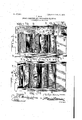
- FIG. 3 is an end view looking in the direction of the arrow Y at the left of Fi 5
- Fig. 4 is a view of the opposite end oft e machine looking in the direction of the arrow X at the right of Fig. 5 is a central vertical section of the machine as inoperationf
- Fig. 6' is a detail section taken on the line 6 6 of Fig. 2.
- 1 1 are supporting standards provided and 5 at each side of the machine for the with braces '2, 3, 4,
- braces 6 and -'7 areprovided for strengthening the main support- Thebracemembers 5, as will 'be noted from the sectional view,
- Fig.2 is
- section taken 3 Fig. 5 constitute 'theside wallsof the feedinghopper, into which grain, &c., to be cleaned in the machine is fed, said hopper comprising the inclined bottom plate 8 and the inclined end plates 9 and 10, which are adapted to close the discharge end of such hopper.
- e plate 10 is made ad- .catenteq Maren 20, 1906.
- the supp of material to the apparatus may be regulated to a nicety upon adjusting said plate 10 by means of the
- the walls 5 are rig uprightsxl 1 in any suitable manner, and sup orted from the walls 5 by means ofv the lin s 18 is a shakerframe, within which-are arranged screens and separating means, the details of which will be hereinafter more fully described.
- the separator comprises the side plates 19, screens and latforms and chutes, so arranged that Wee s, dust, andrubbish may be first separated from the grain, after which the various grains. which may be mixed before entering the machine may be separated the one from the other.
- Rising vertically from the plates 19 is a supportinglate 20, which has at its .upper end the de ectoriplate '21, which is provided for the purpose, of preventing theoverflow of grain, &c., passing from the hopper before referred to, and connected with the vertical plate 20. is a looped rod 22,
- the main driving-gear 25 is su a, shaft 25", disposed in suitab e bearings upon the standard 1, said gear 25 being pro- Iprojects into the dischargevided with an actuating-crank 26, as shown,
- a chain 27 is run over the driving-gear and over the pinion 34,.secured .to the shaft 35 for actuating the mechanism hereinafter described.
- Pitmen 28 28 are pivotally con nected with the lower ends of the links 29, which links are pivoted at 30 and extend thence upwardly, as shown in the detail Fig. 6, where such links are provided with a plurality of openings 31, through either one of which the pin 32 may be projected for connecting said link 29 with the bracket 33,
- the pin 32 is adjustable, so that as the pitmen 28 actuate the links 29 a greater or less thrust will be obtained of the separator as may be required in separating different kinds of grain.
- the pitmen 28 28 are' actuated by the pinions 34 34*, respectively, carriedupon the ends of the shaft 35, to which shaft are rigidly connected arms 36, between which are supported the blades 37 of a fan or wind-wheel, as is common in this class of construction.
- the casing 38 for the fan is preferably left open at both ends, and, as shown in Fig.
- a disk 39 provided with a slot 40, is supported upon the shaft 35 in a manner that said disk 39 may be moved to such positon as will provide a greater or less area of opening into said casing 38, sothat the amount of the blast from said fan may be regulated by means of the disk 39.
- Stones, rubbish, and grain will pass over the screen 42 and onto the screen 45, which is of relatively coarser mesh, but of such size as to permit wheat and oats to pass through the meshes thereof, while the stones and rubbish which will not pass through the screen 45 will fall into the chute 46 at the lower end thereof.
- Below the screen 45 is an inclined chute or platform 47, down which the grain will pass, such grain falling through the port or opening 48 of the platform 47 onto the next screen-section, which comprises a plurality of screens supported within or upon a single removable frame-section 49, as fol lows:
- this .screen is such that wheat will pass through it into the chamber 51; but if oats should be mixed with the wheat such oats would be so light that instead of passing through the screen 50 they will continue, as indicated by the arrow, onto the flexible apron 52, over which the oats will be carried, as indicated by the arrow, into the chute 53.
- wheat, screenings, and chaff will pass, and from such chamber they will pass over the screen 54, through which screenings will pass onto the inclined platform 55, down which they will pass into the spout 56.
- the whole wheat will not pass through the screen 54, but will be carried onward to the screen 57, through which will pass all grades of wheat onto the inclined platform 58, provided with the port or opening 59, through which the wheat will fall upon the screen 60.
- the apron 52 will during the operation of the machine rest in substantially the position shown in Fig. 5, and any oats which will be carried onto the screen 57 will pass between the discharge end of th screen and such apron 52 into the oatsreceptacle 53.
- the screen 60 comprises one of a section of screens, as just before described, and below the screen 60 is a chamber 61, provided with an imperforate inclined bottom upon which the wheat may fall, from which it will pass onto the screen 62, which is of such mesh as to permit screenings, broken and small wheat to pass through, while the best grade of wheat will pass over the screen 62 onto the coarser screen 63, through which it will fall to the inclined platform 64, while chaff, &c., which may have passed with the good wheat to this point, will be carried along to the discharge end of the screen 63 and fall upon the tailboard 65 at the discharge end of such screen, while the apron 66 will perform the same function as in the middle screen-section.
- Tl'e platform 64 is provided with a port 67, through which the best grade of wheat will pass into alinement with the dischargespout 68 from tlte blast-fan before referred to, and by means of the blast generated by said fan the chaff will fall into the receptacle 70, while the wheat will be permitted to fall upon the spout 69, from which it may be conducted to any suitable place of deposit, while the screenings will fall upon the inclined platform 71, from which said screenings will pass to the discharge-spout 72 to any suitable place of deposit, as the receptacle 73.
- the screen-casing has mounted therein three screen-frames A B C, respectively.
- Frame A has mounted therein a fine and a coarse screen
- frames B C have two coarse screens at different planes
- extensions 74 On the braces 3 are provided extensions 74, and on the braces 6.are provided extensions 75. Suitable uprights 76 support the outer ends of the extensions 74, and diagonal braces 77 extend from the uprights to said extensions 74. Suitably supported between said extensions is an elevated casing 78, its
- a'box-like structure 78* disposed adjacent the spout which delivers the cleaned grain.
- a shaft 79 Disposed in the lower end of the elevated casing 78 is a shaft 79, on the outer end of which is provided a gear 80, over which passes a chain 81, which is passed over the gear-wheel 34*, secured to the shaft 35.
- a sprocket-wheel 82 Disposed in the lower end of the elevated casing 78 is a shaft 79, on the outer end of which is provided a gear 80, over which passes a chain 81, which is passed over the gear-wheel 34*, secured to the shaft 35.
- the arbor 83 on 'whichis securedQthe sprocket-wheel 84.
- a chain 85 is passed over the sprocket-wheels 82 and 84, and suitably secured upon said chain are buckets 86, 'ada ted to convey the cleaned grain from the d box-like receptacle to a chute 87, the lower end offlwhich is provided with hooks sai 88, adapted to hold a bag 89, the' bottom of which is supported by the platform 90.
- a reciprocatory screen-casing oppositely-inclined latforms in said casing, an upper screen-frame, a coarse and a fine screen in said frame, a plurality of screen-frames at lower planes in said casing, coarse screens in such frames at different planes therein, a
Landscapes
- Adjustment And Processing Of Grains (AREA)
Description
PATBNTED MAR. 20, 1906.
I GRAINGLEANING AND SEBARATING MACHINE.
APYLIOATIQK FILED DBO. 3, 19 04.
- Witnesses:
4 SHEET8-SHBET 1.
a I Caz-1.
.P/ZZZljJMflpyp Inventor,
Attorneys PATENTED MAR. 20, 1906.- ,4 P. MOON. v GRAIN CLEANING, AND SEPARATING MACHINE.
' APPLICATION FILED 1320.3,1904.
Y snnnTs,sn-nm z.
a/ 5 J7 Witnessif: Z
. f/zZz vflfiwz W n v y 15m I p Attarney GRAIN ULEANING Am .np'umnon rznnpojnn'o. a, 1904.
"Witnesses:
I El -MOON.
. 'IPATENTED MAR. 20, 190
.SEPAR'ATING- M CHINE.
' 4 snnmsw ET 3.
N i 3% Inventor,
' Attorneys No.8"l5,45'7. v PATHNTED MAR. 20, 1906.
. P. MOON.
GRAIN CLEANING AND SEPARATING MACHINE.
APPLICATION FILED DEO.3,19 04.
v 59, I H v I I 6:1
'MMIHL HIMHWWW v I I ,.-"f/Z Z% v Inventor I A: I.
Attor'neys UNITED STATES PHIL-11 MOON, OF BRANDON, CANADA,
PATENT OFFICE GRAIN CLEANING AND SEP-ARATITING MACHINE.
Specification of Letters Eatent.
Application filed December 3, 1904. Serial No. 235,392-
To all whom it may concern.
Be it known that I, PHILIP MOON, a subject of the King of Great Britain, residing at Brandon, county of Brandon, in the Province of Manitoba, Oanada,have invented certam new and useful Improvements in Gram Cleaning and Separating Machines; and I do hereby declare that the following isa full, clear, and exact description ofthe invention,
such as will enable others skilled in the art to whichit appertains to make and use the same.
This invention relates to new and useful improvements in grain cleaning and separating machines. I
The object of the invention is to provide a power or manually-operablemachine of the,
character described which will separate and clean all kinds of grain and seeds within the one structure by continuous progression ofthe material passing through the same and the invention consists of the construction, combination, and arrangement of parts, as
the claims. i I e In the accompanying. drawings, forming a part of this application, I have illustrated a .form of embodiment of my. invention, .in
ing-frame of the device. 5 5
.Fig. 5'.
whi e intermediate which similar reference 'characters'indicate corresponding parts, and in which Figure 1 isv a side elevation of the machine set up ready for use, certain parts being broken away and shown in section. a partial fragmentary elevation of the opposite side of the machine, certain parts being broken away and shown in section. Fig. 3 is an end view looking in the direction of the arrow Y at the left of Fi 5 Fig. 4 is a view of the opposite end oft e machine looking in the direction of the arrow X at the right of Fig. 5 is a central vertical section of the machine as inoperationf Fig. 6' is a detail section taken on the line 6 6 of Fig. 2. Fig. 7 is a detail fragmentary on line 7 7 of Fig.2, and Fig. 8 is a fragmentary detail illustrating means for keeping the feed-chute from the hopper'openat all times during the operation of the machine.
Referring to thedrawings, 1 1 are supporting standards provided and 5 at each side of the machine for the with braces '2, 3, 4,
pur ose of connecting the standards together,
Fig.2 is
section taken 3 Fig. 5, constitute 'theside wallsof the feedinghopper, into which grain, &c., to be cleaned in the machine is fed, said hopper comprising the inclined bottom plate 8 and the inclined end plates 9 and 10, which are adapted to close the discharge end of such hopper. Toregulate the supply of from the hopper, e plate 10 is made ad- .catenteq Maren 20, 1906.
grain fed to the machine N justable with relation to the platey9, sothat the size of theopening 11 between the plates 8 and 10 may be adjusted at will, lugs 12 being rovided u on the outer face .of the late 10, etween w ich is held the nut or ead 13, ,connected with the screw-threaded rod 14, held in the bearing 15, which, as shown, is
supported upon a brace 16, connected with the end plate 9, while a crank 17 is connected with said screw-threaded rod to rotate it for I, lowering the plate 10 to adjust the area of the opening 11 before the purpose of raising or referred to. Thus the supp of material to the apparatus may be regulated to a nicety upon adjusting said plate 10 by means of the The walls 5 are rig uprightsxl 1 in any suitable manner, and sup orted from the walls 5 by means ofv the lin s 18 is a shakerframe, within which-are arranged screens and separating means, the details of which will be hereinafter more fully described. The separator comprises the side plates 19, screens and latforms and chutes, so arranged that Wee s, dust, andrubbish may be first separated from the grain, after which the various grains. which may be mixed before entering the machine may be separated the one from the other. Rising vertically from the plates 19 is a supportinglate 20, which has at its .upper end the de ectoriplate '21, which is provided for the purpose, of preventing theoverflow of grain, &c., passing from the hopper before referred to, and connected with the vertical plate 20. is a looped rod 22,
(shownin'the sectional'view Fig. 5 and in Fig. 8,) which opening 11 of t hopper, and it is evident t at as the separator is reciprocated, as is common in this class of machines, the cleanout 22 will become efiectivefor the purpose of preventing clogging of the hopper-discharge opening. I
The main driving-gear 25 is su a, shaft 25", disposed in suitab e bearings upon the standard 1, said gear 25 being pro- Iprojects into the dischargevided with an actuating-crank 26, as shown,
ported on IIQ A chain 27 is run over the driving-gear and over the pinion 34,.secured .to the shaft 35 for actuating the mechanism hereinafter described. Pitmen 28 28 are pivotally con nected with the lower ends of the links 29, which links are pivoted at 30 and extend thence upwardly, as shown in the detail Fig. 6, where such links are provided with a plurality of openings 31, through either one of which the pin 32 may be projected for connecting said link 29 with the bracket 33,
which is rigidly secured upon the side of the plates 19, before referred to. The pin 32 is adjustable, so that as the pitmen 28 actuate the links 29 a greater or less thrust will be obtained of the separator as may be required in separating different kinds of grain. The pitmen 28 28 are' actuated by the pinions 34 34*, respectively, carriedupon the ends of the shaft 35, to which shaft are rigidly connected arms 36, between which are supported the blades 37 of a fan or wind-wheel, as is common in this class of construction. The casing 38 for the fan is preferably left open at both ends, and, as shown in Fig. 1, a disk 39, provided with a slot 40, is supported upon the shaft 35 in a manner that said disk 39 may be moved to such positon as will provide a greater or less area of opening into said casing 38, sothat the amount of the blast from said fan may be regulated by means of the disk 39. Supported by the plates 1.9 in any convenient manner, as by means of the bracket 41, are screen sections which, as shown in Fig. 5, have placed immediately below the discharge end of the hopper a fine screen 42, through which fine screen will pass seeds of weeds and dust which it is desired to eliminate from the grain being cleaned, such dust and small seeds passing upon the inclined platform 43 and passing thence to the discharge-spout 44, from which they may be connected to any suitable place of deposit. Stones, rubbish, and grain will pass over the screen 42 and onto the screen 45, which is of relatively coarser mesh, but of such size as to permit wheat and oats to pass through the meshes thereof, while the stones and rubbish which will not pass through the screen 45 will fall into the chute 46 at the lower end thereof. Below the screen 45 is an inclined chute or platform 47, down which the grain will pass, such grain falling through the port or opening 48 of the platform 47 onto the next screen-section, which comprises a plurality of screens supported within or upon a single removable frame-section 49, as fol lows: There are three sections of wire, perforated metal, or other suitable screening material within the section 49, the first of which is a coarse screen 50, upon which the grain passing through the port 48 will fall. The mesh of this .screen is such that wheat will pass through it into the chamber 51; but if oats should be mixed with the wheat such oats would be so light that instead of passing through the screen 50 they will continue, as indicated by the arrow, onto the flexible apron 52, over which the oats will be carried, as indicated by the arrow, into the chute 53. Within the chamber 51 wheat, screenings, and chaff will pass, and from such chamber they will pass over the screen 54, through which screenings will pass onto the inclined platform 55, down which they will pass into the spout 56. The whole wheat, however, will not pass through the screen 54, but will be carried onward to the screen 57, through which will pass all grades of wheat onto the inclined platform 58, provided with the port or opening 59, through which the wheat will fall upon the screen 60. The apron 52 will during the operation of the machine rest in substantially the position shown in Fig. 5, and any oats which will be carried onto the screen 57 will pass between the discharge end of th screen and such apron 52 into the oatsreceptacle 53. The screen 60 comprises one of a section of screens, as just before described, and below the screen 60 is a chamber 61, provided with an imperforate inclined bottom upon which the wheat may fall, from which it will pass onto the screen 62, which is of such mesh as to permit screenings, broken and small wheat to pass through, while the best grade of wheat will pass over the screen 62 onto the coarser screen 63, through which it will fall to the inclined platform 64, while chaff, &c., which may have passed with the good wheat to this point, will be carried along to the discharge end of the screen 63 and fall upon the tailboard 65 at the discharge end of such screen, while the apron 66 will perform the same function as in the middle screen-section.
Tl'e platform 64 is provided with a port 67, through which the best grade of wheat will pass into alinement with the dischargespout 68 from tlte blast-fan before referred to, and by means of the blast generated by said fan the chaff will fall into the receptacle 70, while the wheat will be permitted to fall upon the spout 69, from which it may be conducted to any suitable place of deposit, while the screenings will fall upon the inclined platform 71, from which said screenings will pass to the discharge-spout 72 to any suitable place of deposit, as the receptacle 73.
The operation of the machine will be understood from the foregoing description of the comparative parts, from which it will be seen that grain may be dumped into the supply-hopper and fed through the discharge from such hopper onto the uppermost screen, from which it will pass in the path of travel hereinbefore indicated, and during its descent from the uppermost to the lowermost level of the separator the weeds, dust, rubbish, screenings, oats, and chaff will be separated from the best grade of wheat, which will be entirely freed from all foreign impurities when it the machine.
As will be noted, the screen-casinghas mounted therein three screen-frames A B C, respectively. Frame A has mounted therein a fine and a coarse screen, while frames B C have two coarse screens at different planes,
, with a fine intermediate screen in each. Be-
tween the coarse screens in frames B O are secured the flexible aprons 52 and 66, before referred to, and all of the frames are'slidably mounted in the screen-casing,so as to be'removable when necessary for repairs, &c.
On the braces 3 are provided extensions 74, and on the braces 6.are provided extensions 75. Suitable uprights 76 support the outer ends of the extensions 74, and diagonal braces 77 extend from the uprights to said extensions 74. Suitably supported between said extensions is an elevated casing 78, its
lower end terminating in a'box-like structure 78*, disposed adjacent the spout which delivers the cleaned grain. Disposed in the lower end of the elevated casing 78 is a shaft 79, on the outer end of which is provided a gear 80, over which passes a chain 81, which is passed over the gear-wheel 34*, secured to the shaft 35. ,Within the casing supported on said shaft 7 9-is a sprocket-wheel 82, and
wit in the upper end of the casing is mounted the arbor 83, on 'whichis securedQthe sprocket-wheel 84. A chain 85 is passed over the sprocket- wheels 82 and 84, and suitably secured upon said chain are buckets 86, 'ada ted to convey the cleaned grain from the d box-like receptacle to a chute 87, the lower end offlwhich is provided with hooks sai 88, adapted to hold a bag 89, the' bottom of which is supported by the platform 90.
While Ihave shown in the accompanying reaches the discharge-spout of drawings the it will be understood that I do not limit myself to the precise form shown, for many of the details maybe changed in form or position without affecting the operativeness or ing, an upper screen-frame, a fine screen and a coarse screen in said frame, a lower screenframe in said casing, a plurality of coarse screens, and a finer screen, in saidv lower frame, and a flexible apron connected with said framebetween said coarse screens.
2. In a machine of the character described, a reciprocatory screen-casing, oppositely-inclined latforms in said casing, an upper screen-frame, a coarse and a fine screen in said frame, a plurality of screen-frames at lower planes in said casing, coarse screens in such frames at different planes therein, a
finer screen in each of such frames in substantially the plane of one of said coarse screens, and I flexible aprons connected with said frames between such coarse screens.
, In witness whereof I have hereunto set my hand in the presence. of two witnesses.
\ g l PHILIP MOON.
Witnesses:
M. DALZIEL, H. L. ADOLPH.
preferred form of my invention,
Priority Applications (1)
| Application Number | Priority Date | Filing Date | Title |
|---|---|---|---|
| US23539204A US815457A (en) | 1904-12-03 | 1904-12-03 | Grain cleaning and separating machine. |
Applications Claiming Priority (1)
| Application Number | Priority Date | Filing Date | Title |
|---|---|---|---|
| US23539204A US815457A (en) | 1904-12-03 | 1904-12-03 | Grain cleaning and separating machine. |
Publications (1)
| Publication Number | Publication Date |
|---|---|
| US815457A true US815457A (en) | 1906-03-20 |
Family
ID=2883939
Family Applications (1)
| Application Number | Title | Priority Date | Filing Date |
|---|---|---|---|
| US23539204A Expired - Lifetime US815457A (en) | 1904-12-03 | 1904-12-03 | Grain cleaning and separating machine. |
Country Status (1)
| Country | Link |
|---|---|
| US (1) | US815457A (en) |
-
1904
- 1904-12-03 US US23539204A patent/US815457A/en not_active Expired - Lifetime
Similar Documents
| Publication | Publication Date | Title |
|---|---|---|
| US20200290087A1 (en) | Sieve device for fine cleaning of grainy material | |
| US1564914A (en) | Almond hulling and separating machine | |
| US815457A (en) | Grain cleaning and separating machine. | |
| US850447A (en) | Separating or grading machine. | |
| US816735A (en) | Apparatus for separating rubber from canvas, metal, and other material. | |
| US641986A (en) | Flour-bolt. | |
| US532266A (en) | Apparatus for separating precious metals from sand | |
| US1118221A (en) | Seed-separator. | |
| US399486A (en) | Separator | |
| US1147283A (en) | Pea-grader. | |
| US783269A (en) | Rice grading and separating means. | |
| US148229A (en) | Improvement in middlings-purifiers | |
| US1398275A (en) | Grain cleaner, separator, and drier | |
| CN117531690B (en) | A feeding screening device for grain dryer | |
| US393825A (en) | Bolting reel | |
| US107856A (en) | Improvement in grain-separators | |
| US300621A (en) | Chaeles b | |
| US65818A (en) | Apparatus foe washing and sep abating coal | |
| US211571A (en) | Improvement in grain-separators | |
| US1144368A (en) | Fanning-mill. | |
| US317813A (en) | Grain-separator | |
| US188345A (en) | Improvement in grain-separators | |
| US625295A (en) | Screening-machine | |
| US1202375A (en) | Screening apparatus. | |
| US801207A (en) | Seed-cleaner and grain-separator. |