US8210543B2 - Seal for a bushing - Google Patents
Seal for a bushing Download PDFInfo
- Publication number
- US8210543B2 US8210543B2 US12/456,183 US45618309A US8210543B2 US 8210543 B2 US8210543 B2 US 8210543B2 US 45618309 A US45618309 A US 45618309A US 8210543 B2 US8210543 B2 US 8210543B2
- Authority
- US
- United States
- Prior art keywords
- sealing
- core
- sleeve
- bushing assembly
- face
- Prior art date
- Legal status (The legal status is an assumption and is not a legal conclusion. Google has not performed a legal analysis and makes no representation as to the accuracy of the status listed.)
- Expired - Fee Related, expires
Links
- 238000007789 sealing Methods 0.000 claims abstract description 82
- 230000000149 penetrating effect Effects 0.000 description 3
- 238000005516 engineering process Methods 0.000 description 2
- 238000009434 installation Methods 0.000 description 2
- 239000000463 material Substances 0.000 description 2
- 239000002245 particle Substances 0.000 description 2
- 230000002028 premature Effects 0.000 description 2
- 239000011324 bead Substances 0.000 description 1
- 239000011248 coating agent Substances 0.000 description 1
- 238000000576 coating method Methods 0.000 description 1
- 230000006835 compression Effects 0.000 description 1
- 238000007906 compression Methods 0.000 description 1
- 230000000694 effects Effects 0.000 description 1
- 229920001971 elastomer Polymers 0.000 description 1
- 239000000806 elastomer Substances 0.000 description 1
- 239000013536 elastomeric material Substances 0.000 description 1
- -1 for instance Substances 0.000 description 1
- 239000004519 grease Substances 0.000 description 1
- 239000000314 lubricant Substances 0.000 description 1
- 238000011089 mechanical engineering Methods 0.000 description 1
- 230000035515 penetration Effects 0.000 description 1
- 238000007670 refining Methods 0.000 description 1
Images


Classifications
-
- F—MECHANICAL ENGINEERING; LIGHTING; HEATING; WEAPONS; BLASTING
- F16—ENGINEERING ELEMENTS AND UNITS; GENERAL MEASURES FOR PRODUCING AND MAINTAINING EFFECTIVE FUNCTIONING OF MACHINES OR INSTALLATIONS; THERMAL INSULATION IN GENERAL
- F16F—SPRINGS; SHOCK-ABSORBERS; MEANS FOR DAMPING VIBRATION
- F16F13/00—Units comprising springs of the non-fluid type as well as vibration-dampers, shock-absorbers, or fluid springs
- F16F13/04—Units comprising springs of the non-fluid type as well as vibration-dampers, shock-absorbers, or fluid springs comprising both a plastics spring and a damper, e.g. a friction damper
- F16F13/06—Units comprising springs of the non-fluid type as well as vibration-dampers, shock-absorbers, or fluid springs comprising both a plastics spring and a damper, e.g. a friction damper the damper being a fluid damper, e.g. the plastics spring not forming a part of the wall of the fluid chamber of the damper
- F16F13/08—Units comprising springs of the non-fluid type as well as vibration-dampers, shock-absorbers, or fluid springs comprising both a plastics spring and a damper, e.g. a friction damper the damper being a fluid damper, e.g. the plastics spring not forming a part of the wall of the fluid chamber of the damper the plastics spring forming at least a part of the wall of the fluid chamber of the damper
- F16F13/14—Units of the bushing type, i.e. loaded predominantly radially
- F16F13/1445—Units of the bushing type, i.e. loaded predominantly radially characterised by method of assembly, production or treatment
- F16F13/1454—Sealing of units
-
- F—MECHANICAL ENGINEERING; LIGHTING; HEATING; WEAPONS; BLASTING
- F16—ENGINEERING ELEMENTS AND UNITS; GENERAL MEASURES FOR PRODUCING AND MAINTAINING EFFECTIVE FUNCTIONING OF MACHINES OR INSTALLATIONS; THERMAL INSULATION IN GENERAL
- F16J—PISTONS; CYLINDERS; SEALINGS
- F16J15/00—Sealings
- F16J15/16—Sealings between relatively-moving surfaces
- F16J15/32—Sealings between relatively-moving surfaces with elastic sealings, e.g. O-rings
- F16J15/3204—Sealings between relatively-moving surfaces with elastic sealings, e.g. O-rings with at least one lip
- F16J15/3224—Sealings between relatively-moving surfaces with elastic sealings, e.g. O-rings with at least one lip capable of accommodating changes in distances or misalignment between the surfaces, e.g. able to compensate for defaults of eccentricity or angular deviations
Definitions
- the invention relates to a bushing, comprising a core, a sleeve surrounding the core and a spring element that is arranged between the core and the sleeve.
- German patent application DE 102 20 219 B4 discloses a cylindrical bushing that has a core and a sleeve between which a spring element is arranged. In the non-load state, the spring element has a larger radial extension than after it has been installed. As a result, after its installation, the spring element exhibits a high radial bias.
- Such bushings have the advantage that they have a high radial stiffness with a concurrently low torsional stiffness. Owing to the high bias, it is not necessary to connect the spring element to the core or to the sleeve by a bonded joint.
- the invention is based on the objective of refining the bushing in such a way that the spring element is protected against the penetration of dirt.
- a bushing comprising a core, a sleeve that surrounds the core and a spring element that is arranged between the core and the sleeve, characterized in that, on at least one face of the bushing, there is a sealing element that seals the spring element vis-à-vis the environment.
- a sealing element is arranged on at least one face of the bushing, said sealing element sealing the spring element vis-à-vis the environment.
- This sealing element prevents dirt particles from penetrating into the space between the core and the sleeve, something that could otherwise cause damage, especially to the areas where the spring element is joined to the core and the sleeve.
- This is particularly advantageous when the spring element is not connected to the core or sleeve by a bonded joint, and the spring element is under radial bias only because of strong compression that clamps it between the core and the sleeve. In this case, especially if relative movements occur, dirt could penetrate between the spring element and the adjacent surfaces and damage the material of the spring element, thereby causing premature wear and tear.
- the sealing element seals the spring element vis-à-vis the environment.
- the sealing element is configured in such a way that it only offers a slight resistance to the movements for which the bushing is designed.
- a bushing having a radially compressed spring element is preferably configured for movements in the rotational direction as well as in the axial direction, and it is quite soft in these directions. In the radial direction, however, such a bushing is hard because of the bias on the spring element.
- the sealing element for such a bushing is configured in such a way that it executes relative movements with low resistance between the core and the sleeve in the rotational direction as well as in the axial direction.
- the sealing element can have a first sealing section and a second sealing section, whereby the first sealing section lies against the core so as to create a seal, while the second sealing section lies against the sleeve so as to create a seal.
- the sealing section lies over the entire surface so as to create a seal against the inner circumference of the sleeve and against the outer circumference of the core, thereby creating a secure seal.
- the sealing element can be largely integrated into the bushing, so that very little changes in terms of the overall dimensions of the bushing.
- the first sealing section and the second sealing section can be joined to each other by means of a web.
- the web is a thin-walled part that, depending on the orientation, allows a high degree of flexibility of the relative movement of the two sealing sections.
- the web can be configured as a bellows, as a result of which it is particularly flexible in the radial direction.
- the web can be configured in such a way that the sealing element has a Z-shaped configuration as seen in a cross section. This means that the web is oblique with respect to the two sealing sections and runs, for example, from one face to the other face. This yields a high degree of flexibility of the sealing element, especially in the rotational direction.
- a support element can be associated with the first sealing section and/or with the second sealing section. This translates into a higher stability of the sealing element.
- the support rings can be configured in such a way that the sealing element lies with a high bias against the core and the sleeve.
- the sealing surfaces associated with the sealing sections can be provided with profiling.
- the profiling improves the sealing effect of the sealing element.
- the sealing element can extend onto the face of the core. This results in a stop function by means of which it is particularly easy to install the sealing element.
- the support element associated with the core can have an L-shaped configuration. Here, one section of the support element comes into contact with the face of the core directly or indirectly, thereby forming an encircling stop for the sealing element.
- the sealing element can be provided with a stop contour on the face that is facing away from the core.
- the stop contour can be formed by a ring-shaped bead or by elevations distributed along the circumference, and it is made of an elastomeric material.
- the stop contour can be brought into contact with a component mounted on the core, whereby the stop is very gentle on the material since it is made of elastomer.
- the sealing element can have a protruding sealing lip on the face that is facing away from the core.
- the sealing lip can be brought into contact with an adjacent component, for instance, with a component mounted on the core, and it prevents dirt from penetrating into the space between the bushing and the component.
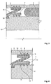
- FIG. 1 shows a bushing with a sealing element
- FIG. 2 shows a detailed view of the sealing element shown in FIG. 1 ;
- FIG. 3 shows a bushing with a sealing element
- FIG. 4 is a detailed view of the sealing element shown in FIG. 3 .
- FIG. 1 shows a bushing 1 , configured here as an elastomeric articulated joint for use in general mechanical engineering, in drive technology or in automotive technology.
- Such articulated joints serve as bushings for collapsible booths, housing covers, levers, linkages, motor rockers, oscillating screens or vibrating tables.
- the bushing 1 consists of a core 2 , a sleeve 3 that surrounds the core 2 , and a spring element 4 that is arranged between the core 2 and the sleeve 3 .
- the spring element 4 in its non-load state has a smaller axial extension and a larger radial extension than after its installation between the core 2 and the sleeve 3 .
- the spring element 4 is strongly compressed in the radial direction and is thus particularly stiff in the radial direction, with a concurrently reduced stiffness in the axial direction as well as in the rotational direction. Owing to the high bias of the spring element 4 , it is not necessary to connect the spring element 4 to the core 2 or to the sleeve 3 by a bonded joint.
- a sealing element 6 that seals the sealing element 4 vis-à-vis the environment is arranged on both faces 5 of the bushing 1 .
- the sealing element is arranged in the concentric gap between the core 2 and the sleeve 3 , as a result of which the axial extension of the bushing 1 remains unchanged.
- the sealing element 6 has a first sealing section 7 and a second sealing section 8 , whereby the first sealing section 7 lies so as to create a seal against the outer circumference of the core 2 , while the second sealing section 8 lies so as to create a seal against the inner circumference of the sleeve 3 .
- the first sealing section 7 and the second sealing section 8 are joined to each other by a web 9 , whereby the web 9 is configured in such a way that the sealing element 6 has a Z-shaped configuration as seen in a cross section.
- a support element 10 , 11 is associated with the first sealing section 7 and with the second sealing section 8 , respectively, and the sealing surfaces associated with the sealing sections 7 , 8 are provided with profiling 12 .
- the support element 10 associated with the core 2 has an L-shaped configuration, as a result of which the sealing element 6 extends to the face 13 of the core 2 .
- the sealing element 6 is provided with a stop contour 14 and the sealing element 6 has a protruding sealing lip 15 on the face that is facing away from the core 2 .
- the core 2 is slid onto a journal or pin 16 and attached there. The attachment can be effectuated in such a way that the core 2 can rotate freely on the pin 16 .
- the space between the core 2 and the pin 16 can be filled with a lubricant, for instance, grease.
- the spring element 4 is free of torsional loads that could lead to an overload of the spring element 4 .
- the inner circumference of the core 2 is provided with a friction-reducing coating 18 .
- the gap is closed off by another sealing element 17 .
- This additional sealing element 17 is configured here as an O-ring that is arranged in a groove in the core 2 .
- FIG. 2 shows a detailed view of the sealing element 6 depicted in FIG. 1 .
- FIG. 3 shows a bushing as depicted in FIG. 1 , whereby the leg of the support element is associated with the core 2 and extends in the radial direction, said leg being configured to be short so that it has a stop function for installing the sealing element 6 on the core 2 .
- the leg of the support element is associated with the core 2 and extends in the radial direction, said leg being configured to be short so that it has a stop function for installing the sealing element 6 on the core 2 .
- neither a stop contour not a sealing lip is provided.
- FIG. 4 shows a detailed view of the sealing element 6 depicted in FIG. 3 .
Landscapes
- Engineering & Computer Science (AREA)
- General Engineering & Computer Science (AREA)
- Mechanical Engineering (AREA)
- Manufacturing & Machinery (AREA)
- Sealing Of Bearings (AREA)
- Sealing Devices (AREA)
- Springs (AREA)
Applications Claiming Priority (3)
| Application Number | Priority Date | Filing Date | Title |
|---|---|---|---|
| DE102008028115 | 2008-06-13 | ||
| DE102008028115.8-12 | 2008-06-13 | ||
| DE102008028115A DE102008028115A1 (de) | 2008-06-13 | 2008-06-13 | Lager |
Publications (2)
| Publication Number | Publication Date |
|---|---|
| US20090309314A1 US20090309314A1 (en) | 2009-12-17 |
| US8210543B2 true US8210543B2 (en) | 2012-07-03 |
Family
ID=41055207
Family Applications (1)
| Application Number | Title | Priority Date | Filing Date |
|---|---|---|---|
| US12/456,183 Expired - Fee Related US8210543B2 (en) | 2008-06-13 | 2009-06-12 | Seal for a bushing |
Country Status (5)
| Country | Link |
|---|---|
| US (1) | US8210543B2 (de) |
| EP (1) | EP2133590A3 (de) |
| CN (1) | CN101660582B (de) |
| DE (1) | DE102008028115A1 (de) |
| RU (1) | RU2415318C2 (de) |
Cited By (3)
| Publication number | Priority date | Publication date | Assignee | Title |
|---|---|---|---|---|
| US20110049815A1 (en) * | 2009-08-25 | 2011-03-03 | Freudenberg-Nok General Partnership | Low Load Offset Seal |
| US20110227291A1 (en) * | 2008-09-24 | 2011-09-22 | James Walker & Co. Ltd. | Energised Seal |
| US20180142789A1 (en) * | 2012-05-18 | 2018-05-24 | Freudenberg-Nok General Partnership | Low load seal with outer diameter flap |
Families Citing this family (10)
| Publication number | Priority date | Publication date | Assignee | Title |
|---|---|---|---|---|
| US10808756B2 (en) | 2007-04-13 | 2020-10-20 | Waukesha Bearings Corporation | Compliant bearing |
| DE102011056013B4 (de) * | 2011-12-05 | 2024-03-28 | Dr. Ing. H.C. F. Porsche Aktiengesellschaft | Mehrteiliges Führungslager zum Einsatz in einem Kfz-Lagerbock |
| DE102014102715B3 (de) * | 2014-02-28 | 2015-07-16 | Jenoptik Optical Systems Gmbh | Spannungsarme Fassungsbaugruppe |
| DE102015100429B4 (de) | 2015-01-13 | 2018-07-26 | Trelleborgvibracoustic Gmbh | Ausgleichsmembran für ein hydraulisch dämpfendes Lager |
| US10415642B2 (en) * | 2015-06-09 | 2019-09-17 | Aktiebolaget Skf | Coupling system of a sealing assembly with a rotating annular element |
| CN106438715B (zh) | 2015-08-07 | 2020-03-17 | 舍弗勒技术股份两合公司 | 用于轴承的密封结构 |
| CN108343703B (zh) * | 2017-01-23 | 2020-09-22 | 株洲时代瑞唯减振装备有限公司 | 一种用于液压衬套的刚度调节装置和液压衬套 |
| EP4006388A4 (de) | 2019-07-24 | 2023-07-26 | NOK Corporation | Dichtungsvorrichtung |
| DE102019133637B4 (de) * | 2019-12-10 | 2024-12-12 | Audi Ag | Hydraulisches Lager und Verfahren zur Herstellung eines hydraulischen Lagers |
| US12188561B2 (en) | 2022-10-13 | 2025-01-07 | Freudenberg-Nok General Partnership | High pressure offset seal |
Citations (23)
| Publication number | Priority date | Publication date | Assignee | Title |
|---|---|---|---|---|
| US2997318A (en) * | 1957-08-01 | 1961-08-22 | Parker Hannifin Corp | Sealing rings for rods and shafts |
| US3468171A (en) * | 1966-09-16 | 1969-09-23 | Birfield Eng Ltd | Flexible seals |
| US3948574A (en) * | 1975-06-19 | 1976-04-06 | J. I. Case Company | Joint with a combined seal and bushing |
| US4156532A (en) * | 1975-12-28 | 1979-05-29 | Toyota Jidosha Kogyo Kabushiki Kaisha | Sealing device for an automobile disk brake |
| US4228726A (en) * | 1978-08-01 | 1980-10-21 | Kelsey Hayes Co. | Hydraulic disc brake piston seal |
| US4304416A (en) * | 1978-12-20 | 1981-12-08 | Tokico Ltd. | Dust cover |
| US4537289A (en) * | 1982-06-18 | 1985-08-27 | International Telephone And Telegraph Corporation | Dust boot for a disc-brake actuating cylinder-and-piston unit |
| US4809821A (en) * | 1983-11-14 | 1989-03-07 | Allied-Signal Inc. | Disc brake corrosion barrier |
| DE3740310A1 (de) | 1987-11-27 | 1989-06-08 | Porsche Ag | Hinterachsaufhaengung fuer ein kraftfahrzeug |
| JPH01275926A (ja) | 1988-04-26 | 1989-11-06 | Kurashiki Kako Co Ltd | ブッシュ組立体 |
| US5137285A (en) * | 1986-03-24 | 1992-08-11 | Zahnradfabrik Friedrichshafen Ag | Sealing system for mutually rotating machine parts |
| EP0656271A1 (de) | 1993-07-05 | 1995-06-07 | Jörn GmbH | Gelenklager, insbesondere für einen Achslenker eines Kraftfahrzeugs |
| US5626520A (en) * | 1995-06-14 | 1997-05-06 | The Zeller Corporation | Reversible universal joint seal |
| US6224046B1 (en) * | 1998-01-14 | 2001-05-01 | Honda Giken Kogyo Kabushiki Kaisha | Fluid-filled bushing |
| US6264206B1 (en) * | 1997-10-21 | 2001-07-24 | Yazaki Corporation | Packing hold structure |
| US6298955B1 (en) * | 1999-10-26 | 2001-10-09 | Meritor Heavy Vehicle Systems, Llc | Shaft seal for eccentric air brake lever |
| JP2001275826A (ja) | 2000-03-31 | 2001-10-09 | Tachikawa Kiko Kk | 装飾カーテンレールの取付ブラケット |
| DE10024536A1 (de) | 2000-05-18 | 2001-11-29 | Trelleborg Automotive Tech Ct | Hydraulisch dämpfende Buchse |
| DE10220219A1 (de) | 2002-05-06 | 2003-11-27 | Zf Boge Gmbh | Gummilager |
| US7097004B2 (en) * | 2003-01-24 | 2006-08-29 | Akebono Corporation (North America) | Pressure bleeding boot-type seal |
| US20060220323A1 (en) * | 2005-03-31 | 2006-10-05 | Frostick Lewis A | Static flexible seal |
| US7189162B2 (en) * | 2003-03-12 | 2007-03-13 | American Axle & Manufacturing, Inc. | Universal joint with thrust washer |
| US8028998B2 (en) * | 2006-01-24 | 2011-10-04 | Elringklinger Ag | Radial seal |
Family Cites Families (4)
| Publication number | Priority date | Publication date | Assignee | Title |
|---|---|---|---|---|
| AU462744B2 (en) * | 1973-08-28 | 1975-07-03 | Toyota Jidosha Kogyo Kabushiki Kaisha | Resilient mounting of control arm for motor vehicles |
| US5348337A (en) * | 1991-12-27 | 1994-09-20 | Mazda Motor Corporation | Automobile suspension |
| UA41731C2 (en) * | 2001-02-26 | 2004-10-15 | Slide bearing unit slide bearing unit | |
| CN201023406Y (zh) * | 2007-01-08 | 2008-02-20 | 许容毅 | 摆臂悬架衬套 |
-
2008
- 2008-06-13 DE DE102008028115A patent/DE102008028115A1/de not_active Ceased
-
2009
- 2009-06-10 EP EP09007641.5A patent/EP2133590A3/de not_active Withdrawn
- 2009-06-11 RU RU2009122594/11A patent/RU2415318C2/ru not_active IP Right Cessation
- 2009-06-12 US US12/456,183 patent/US8210543B2/en not_active Expired - Fee Related
- 2009-06-12 CN CN2009102057179A patent/CN101660582B/zh not_active Expired - Fee Related
Patent Citations (26)
| Publication number | Priority date | Publication date | Assignee | Title |
|---|---|---|---|---|
| US2997318A (en) * | 1957-08-01 | 1961-08-22 | Parker Hannifin Corp | Sealing rings for rods and shafts |
| US3468171A (en) * | 1966-09-16 | 1969-09-23 | Birfield Eng Ltd | Flexible seals |
| US3948574A (en) * | 1975-06-19 | 1976-04-06 | J. I. Case Company | Joint with a combined seal and bushing |
| US4156532A (en) * | 1975-12-28 | 1979-05-29 | Toyota Jidosha Kogyo Kabushiki Kaisha | Sealing device for an automobile disk brake |
| US4228726A (en) * | 1978-08-01 | 1980-10-21 | Kelsey Hayes Co. | Hydraulic disc brake piston seal |
| US4304416A (en) * | 1978-12-20 | 1981-12-08 | Tokico Ltd. | Dust cover |
| US4537289A (en) * | 1982-06-18 | 1985-08-27 | International Telephone And Telegraph Corporation | Dust boot for a disc-brake actuating cylinder-and-piston unit |
| US4809821A (en) * | 1983-11-14 | 1989-03-07 | Allied-Signal Inc. | Disc brake corrosion barrier |
| US5137285A (en) * | 1986-03-24 | 1992-08-11 | Zahnradfabrik Friedrichshafen Ag | Sealing system for mutually rotating machine parts |
| DE3740310A1 (de) | 1987-11-27 | 1989-06-08 | Porsche Ag | Hinterachsaufhaengung fuer ein kraftfahrzeug |
| US4981308A (en) | 1987-11-27 | 1991-01-01 | Dr. Ing. H.C.F. Porsche Aktiengesellschaft | Rear axle suspension for a motor vehicle |
| JPH01275926A (ja) | 1988-04-26 | 1989-11-06 | Kurashiki Kako Co Ltd | ブッシュ組立体 |
| EP0656271A1 (de) | 1993-07-05 | 1995-06-07 | Jörn GmbH | Gelenklager, insbesondere für einen Achslenker eines Kraftfahrzeugs |
| US5626520A (en) * | 1995-06-14 | 1997-05-06 | The Zeller Corporation | Reversible universal joint seal |
| US6264206B1 (en) * | 1997-10-21 | 2001-07-24 | Yazaki Corporation | Packing hold structure |
| US6224046B1 (en) * | 1998-01-14 | 2001-05-01 | Honda Giken Kogyo Kabushiki Kaisha | Fluid-filled bushing |
| US6298955B1 (en) * | 1999-10-26 | 2001-10-09 | Meritor Heavy Vehicle Systems, Llc | Shaft seal for eccentric air brake lever |
| JP2001275826A (ja) | 2000-03-31 | 2001-10-09 | Tachikawa Kiko Kk | 装飾カーテンレールの取付ブラケット |
| EP1282788A1 (de) | 2000-05-18 | 2003-02-12 | Trelleborg Automotive Technical Centre GmbH | Hydraulisch dämpfende buchse |
| DE10024536A1 (de) | 2000-05-18 | 2001-11-29 | Trelleborg Automotive Tech Ct | Hydraulisch dämpfende Buchse |
| US6644633B2 (en) | 2000-05-18 | 2003-11-11 | Trelleborg Automotive Technical Centre Gmbh | Hydraulic damping bush |
| DE10220219A1 (de) | 2002-05-06 | 2003-11-27 | Zf Boge Gmbh | Gummilager |
| US7097004B2 (en) * | 2003-01-24 | 2006-08-29 | Akebono Corporation (North America) | Pressure bleeding boot-type seal |
| US7189162B2 (en) * | 2003-03-12 | 2007-03-13 | American Axle & Manufacturing, Inc. | Universal joint with thrust washer |
| US20060220323A1 (en) * | 2005-03-31 | 2006-10-05 | Frostick Lewis A | Static flexible seal |
| US8028998B2 (en) * | 2006-01-24 | 2011-10-04 | Elringklinger Ag | Radial seal |
Non-Patent Citations (1)
| Title |
|---|
| "bushing." Merriam-Webster.com. 2011. http://www.merriam-webster.com/dictionary/bushing?show=0&t=1307036636. (Jun. 2, 2011). * |
Cited By (6)
| Publication number | Priority date | Publication date | Assignee | Title |
|---|---|---|---|---|
| US20110227291A1 (en) * | 2008-09-24 | 2011-09-22 | James Walker & Co. Ltd. | Energised Seal |
| US9261195B2 (en) * | 2008-09-24 | 2016-02-16 | James Walker & Co. Ltd. | Energised seal |
| US20110049815A1 (en) * | 2009-08-25 | 2011-03-03 | Freudenberg-Nok General Partnership | Low Load Offset Seal |
| US9746081B2 (en) * | 2009-08-25 | 2017-08-29 | Freudenberg-Nok General Partnership | Low load offset seal |
| US20180142789A1 (en) * | 2012-05-18 | 2018-05-24 | Freudenberg-Nok General Partnership | Low load seal with outer diameter flap |
| US10514101B2 (en) * | 2012-05-18 | 2019-12-24 | Freudenberg—NOK General Partnership | Low load seal with outer diameter flap |
Also Published As
| Publication number | Publication date |
|---|---|
| DE102008028115A1 (de) | 2009-12-24 |
| US20090309314A1 (en) | 2009-12-17 |
| EP2133590A2 (de) | 2009-12-16 |
| EP2133590A3 (de) | 2014-07-02 |
| CN101660582B (zh) | 2012-03-21 |
| RU2415318C2 (ru) | 2011-03-27 |
| RU2009122594A (ru) | 2010-12-20 |
| CN101660582A (zh) | 2010-03-03 |
Similar Documents
| Publication | Publication Date | Title |
|---|---|---|
| US8210543B2 (en) | Seal for a bushing | |
| JP5584703B2 (ja) | ラジアルシャフトシール、ラジアルシャフトシールアセンブリおよび設置方法 | |
| EP2545307B1 (de) | Dichtung für eine welle mit geringem drehmoment mit verbesserter dichtungselementhaftverbindung | |
| JP6152376B2 (ja) | 増加した可撓性の封止要素を備える流体力学的シール | |
| CN101438084B (zh) | 用于动力转向输入轴的、牢固的密封系统 | |
| KR102225661B1 (ko) | 압력-작동가능한 회전 씰을 구비한 회전 씰 조립체, 및 회전 씰(Rotary Seal assembly with pressure-activatable rotary seal, and rotary seal) | |
| GB2416815A (en) | Bearing seal and swing device | |
| KR100914794B1 (ko) | 볼 소켓 조인트 | |
| WO2014065037A1 (ja) | ボールジョイント用ダストカバー | |
| CN102180201B (zh) | 密封装置以及具有密封装置的链条关节 | |
| JP4898799B2 (ja) | 独立したシーリングリップを有するシャフトシール | |
| US20020172442A1 (en) | Bearing arrangement for a shaft bearing | |
| CN105465204A (zh) | 万向节 | |
| JP2013527904A (ja) | シールアッセンブリおよび該シールアッセンブリを備えた軌道のジョイント | |
| JP3191013U (ja) | オイルシール | |
| CN108278367B (zh) | 用于轴的能够径向移位的密封组件 | |
| CN114508548A (zh) | 用于万向接头轴承的组件 | |
| GB2140101A (en) | Liquid pump seal | |
| JP6804362B2 (ja) | 密封装置 | |
| JP2007247708A (ja) | 軸付きシール | |
| WO2019054156A1 (ja) | ボールジョイント用ダストカバーの取付構造、ダストカバー、及びダストカバー付きボールジョイント | |
| JP3000280U (ja) | 軸受の密封装置 | |
| CN113565961A (zh) | 密封装置 | |
| KR101674424B1 (ko) | 자동차 엔진미션용 저마찰 회전용 샤프트 씰 | |
| WO2020076639A1 (en) | Shaft seal assembly |
Legal Events
| Date | Code | Title | Description |
|---|---|---|---|
| AS | Assignment |
Owner name: CARL FREUDENBERG KG PATENTE UND MARKEN, GERMANY Free format text: ASSIGNMENT OF ASSIGNORS INTEREST;ASSIGNORS:ERL, ANDREAS;EBERT, MICHAEL;DJAHANI, MAJID;REEL/FRAME:023069/0043 Effective date: 20090629 |
|
| ZAAA | Notice of allowance and fees due |
Free format text: ORIGINAL CODE: NOA |
|
| ZAAB | Notice of allowance mailed |
Free format text: ORIGINAL CODE: MN/=. |
|
| STCF | Information on status: patent grant |
Free format text: PATENTED CASE |
|
| FPAY | Fee payment |
Year of fee payment: 4 |
|
| MAFP | Maintenance fee payment |
Free format text: PAYMENT OF MAINTENANCE FEE, 8TH YEAR, LARGE ENTITY (ORIGINAL EVENT CODE: M1552); ENTITY STATUS OF PATENT OWNER: LARGE ENTITY Year of fee payment: 8 |
|
| FEPP | Fee payment procedure |
Free format text: MAINTENANCE FEE REMINDER MAILED (ORIGINAL EVENT CODE: REM.); ENTITY STATUS OF PATENT OWNER: LARGE ENTITY |
|
| LAPS | Lapse for failure to pay maintenance fees |
Free format text: PATENT EXPIRED FOR FAILURE TO PAY MAINTENANCE FEES (ORIGINAL EVENT CODE: EXP.); ENTITY STATUS OF PATENT OWNER: LARGE ENTITY |
|
| STCH | Information on status: patent discontinuation |
Free format text: PATENT EXPIRED DUE TO NONPAYMENT OF MAINTENANCE FEES UNDER 37 CFR 1.362 |
|
| FP | Lapsed due to failure to pay maintenance fee |
Effective date: 20240703 |