US8226325B1 - Wave suppressor and sediment collection system - Google Patents
Wave suppressor and sediment collection system Download PDFInfo
- Publication number
- US8226325B1 US8226325B1 US12/576,359 US57635909A US8226325B1 US 8226325 B1 US8226325 B1 US 8226325B1 US 57635909 A US57635909 A US 57635909A US 8226325 B1 US8226325 B1 US 8226325B1
- Authority
- US
- United States
- Prior art keywords
- water
- sediment
- section
- flow
- pipes
- Prior art date
- Legal status (The legal status is an assumption and is not a legal conclusion. Google has not performed a legal analysis and makes no representation as to the accuracy of the status listed.)
- Active, expires
Links
- 239000013049 sediment Substances 0.000 title claims abstract description 149
- XLYOFNOQVPJJNP-UHFFFAOYSA-N water Substances O XLYOFNOQVPJJNP-UHFFFAOYSA-N 0.000 claims abstract description 125
- 230000009471 action Effects 0.000 claims abstract description 22
- 238000000034 method Methods 0.000 claims abstract description 10
- 239000012530 fluid Substances 0.000 claims abstract description 5
- 239000000463 material Substances 0.000 claims description 28
- 238000003756 stirring Methods 0.000 claims description 7
- 238000004873 anchoring Methods 0.000 claims description 5
- 238000005086 pumping Methods 0.000 claims description 2
- 238000013022 venting Methods 0.000 claims 1
- 239000011435 rock Substances 0.000 description 18
- 230000004888 barrier function Effects 0.000 description 12
- 230000003628 erosive effect Effects 0.000 description 10
- 239000004576 sand Substances 0.000 description 5
- 229920001903 high density polyethylene Polymers 0.000 description 4
- 239000004700 high-density polyethylene Substances 0.000 description 4
- 229940063583 high-density polyethylene Drugs 0.000 description 4
- 230000008901 benefit Effects 0.000 description 3
- 230000000694 effects Effects 0.000 description 3
- 230000036961 partial effect Effects 0.000 description 3
- 239000002689 soil Substances 0.000 description 3
- 238000011084 recovery Methods 0.000 description 2
- 230000009467 reduction Effects 0.000 description 2
- 230000000284 resting effect Effects 0.000 description 2
- 244000236458 Panicum colonum Species 0.000 description 1
- 238000009825 accumulation Methods 0.000 description 1
- 230000009286 beneficial effect Effects 0.000 description 1
- 230000008859 change Effects 0.000 description 1
- 238000000151 deposition Methods 0.000 description 1
- 238000011033 desalting Methods 0.000 description 1
- 238000013461 design Methods 0.000 description 1
- 238000011161 development Methods 0.000 description 1
- 238000005553 drilling Methods 0.000 description 1
- 230000009969 flowable effect Effects 0.000 description 1
- 230000001939 inductive effect Effects 0.000 description 1
- 238000005259 measurement Methods 0.000 description 1
- 231100000989 no adverse effect Toxicity 0.000 description 1
- 239000011236 particulate material Substances 0.000 description 1
- 230000000737 periodic effect Effects 0.000 description 1
- 230000008569 process Effects 0.000 description 1
- 238000011160 research Methods 0.000 description 1
- 230000002441 reversible effect Effects 0.000 description 1
- 150000003839 salts Chemical class 0.000 description 1
- 238000009991 scouring Methods 0.000 description 1
- 239000011343 solid material Substances 0.000 description 1
- 239000000126 substance Substances 0.000 description 1
- 230000001960 triggered effect Effects 0.000 description 1
Images




Classifications
-
- E—FIXED CONSTRUCTIONS
- E02—HYDRAULIC ENGINEERING; FOUNDATIONS; SOIL SHIFTING
- E02B—HYDRAULIC ENGINEERING
- E02B3/00—Engineering works in connection with control or use of streams, rivers, coasts, or other marine sites; Sealings or joints for engineering works in general
- E02B3/04—Structures or apparatus for, or methods of, protecting banks, coasts, or harbours
- E02B3/06—Moles; Piers; Quays; Quay walls; Groynes; Breakwaters ; Wave dissipating walls; Quay equipment
-
- Y—GENERAL TAGGING OF NEW TECHNOLOGICAL DEVELOPMENTS; GENERAL TAGGING OF CROSS-SECTIONAL TECHNOLOGIES SPANNING OVER SEVERAL SECTIONS OF THE IPC; TECHNICAL SUBJECTS COVERED BY FORMER USPC CROSS-REFERENCE ART COLLECTIONS [XRACs] AND DIGESTS
- Y02—TECHNOLOGIES OR APPLICATIONS FOR MITIGATION OR ADAPTATION AGAINST CLIMATE CHANGE
- Y02A—TECHNOLOGIES FOR ADAPTATION TO CLIMATE CHANGE
- Y02A10/00—TECHNOLOGIES FOR ADAPTATION TO CLIMATE CHANGE at coastal zones; at river basins
- Y02A10/11—Hard structures, e.g. dams, dykes or breakwaters
Definitions
- the present invention relates to protection from coastline erosion caused by wave action or tidal surge and the restoration of coastline lost from such wave action or tidal surge activity. More particularly, the present invention relates to a wave suppressor and sediment collection system (sometimes referred to as the WSSC System) which is transportable and can be installed along a coastline which provides a sufficient barrier to disrupt the tidal wave flow into the coastline while at the same time allowing sediment to be carried through the system by the wave action and water currents and to be trapped and deposited at points between the system and the coastline to allow coastline restoration to occur.
- a wave suppressor and sediment collection system (sometimes referred to as the WSSC System) which is transportable and can be installed along a coastline which provides a sufficient barrier to disrupt the tidal wave flow into the coastline while at the same time allowing sediment to be carried through the system by the wave action and water currents and to be trapped and deposited at points between the system and the coastline to allow coastline restoration to occur.
- the first is a system, such as was provided by the barrier islands years ago, which would hinder or reduce the surge of tidal water inland during normal tidal cycles, and also during storms, so that the surge does not damage the coastline.
- a transportable system to reduce tidal surge wave action and provide land restoration along the shore of a body of water, such as a coastline which includes a plurality of interconnected sections of the system, each section including a base, a forward wall, and a rear wall, having a plurality of fluid flow pipes extending from the forward wall to the rear wall, for allowing water including sediment to flow into the pipes at the forward wall and exit the pipes at the rear wall.
- a one-way valve member at the rear wall exit of each pipe, so that water carrying sediment cannot return through the pipe as the wave action recedes from the coastline.
- a flow opening including a weir between multiple sections so that water is able to flow therethrough.
- Each of the sections would be self-contained, and constructed of a material to allow each section to be floated or transported to a location, wherein material, such as water, or the like, can be pumped into each section resulting in the section to sink and rest on the floor of the body of water, with an upper portion of the section extending a distance above the water surface.
- the sections would be interconnected and anchored to the floor, so as to provide a continuous system, interrupted only by the water return outlets as stated earlier.
- the systems described above would further provide inlet and outlet valves on each individual section for allowing material to be pumped into each section in order to sink each section as described earlier; and when sections have to be transported to another location the valving would allow the material to be pumped from each section, resulting in each section becoming buoyant and transportable or barged to another location to be reassembled into multi-sections as described earlier.
- each section would include a shelf or shoulder extending outward below each row of water flow pipes so as to catch any sediment that may not flow through the pipes initially, but would be carried through by a subsequent wave action.
- the system as described above would include a secondary system stationed in the water ahead of the system, which would include one or multiple barges, each barge having an air compressor system, preferably powered by wind and solar energy, to buildup compressed air in tanks, and upon water reaching a certain level, automatically releasing the compressed air through openings at the ends of a plurality of air lines which would be able to rove along the water bottom, resulting in the pressurized air stirring and fluffing up sand and silt from the water bottom.
- the entire system could be relocated to another position in order to build up sediment in another area.
- the entire system could stretch over a short distance, or it could stretch over miles of coastline, depending on the need in an area.
- HDPE high density poly ethylene
- lightweight concrete designed to float or that can be made from recycled rubber, such as used tires, or use the most economical material.
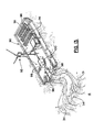
- FIG. 1 is an overall perspective view of a section in the preferred embodiment of the WSSC System of the present invention
- FIG. 2 is a side cutaway view along lines 2 - 2 in FIG. 1 of the preferred embodiment of the WSSC System of the present invention
- FIG. 3 is a rear partial cutaway view along lines 3 - 3 in the preferred embodiment of the WSSC System of the present invention
- FIGS. 4 through 7 illustrate the method of installing the components of the WSSC System of the present invention
- FIG. 8 is a partial overall view of the preferred embodiment of the WSSC System of the present invention being anchored in place while also illustrating water returning through the a weir between sections;
- FIG. 9 illustrates a typical anchor utilized to anchor sections into the water bottom in the WSSC System of the present invention.
- FIG. 10 is another side cutaway of the preferred embodiment of the WSSC System of the present invention illustrating water carrying sediment through the system;
- FIG. 11 is a side cutaway of the preferred embodiment of the WSSC System of the present invention illustrating sediment buildup to the rear of the system;
- FIG. 12A is an aerial view of the WSSC System in place along a shoreline in a body of water;
- FIG. 12B is an aerial view of the WSSC System in place along a shoreline in a body of water with sediment being pumped in via a pipe from the shore;
- FIG. 13 is an overall view of a system utilized to stir up sediment to be carried by the water through the WSSC System of the present invention
- FIG. 14 is an aerial view of the sediment being stirred up by the system described in FIG. 13 ;
- FIG. 15 is a view along lines 15 - 15 in FIG. 14 , which illustrates one of the buoys used to support the net surrounding the sediment stirring system illustrated in FIG. 13 ;
- FIG. 16 is an overall view of an alternative embodiment of a section used in the WSSC System of the present invention.
- FIG. 17 is a side cutaway view of the alternative embodiment of a section taken along lines 17 - 17 in FIG. 16 ;
- FIGS. 18 through 24 illustrate the principal embodiment of the WSSC System of the present invention as it would be installed to function positioned through a rock jetty;
- FIG. 25 illustrates a second embodiment of the WSSC System as it would be installed within a rock jetty.
- FIGS. 1 through 25 illustrate the preferred embodiment of the Wave Suppressor and Sediment Collection (WSSC) System 10 of the present invention, as seen in overall aerial view in FIG. 12A , where the system 10 is in place near a shoreline 15 .
- WSSC Wave Suppressor and Sediment Collection
- FIGS. 1 through 17 illustrate a second embodiment of the WSSC System positioned within a rock jetty. The WSSC System in place near a shore line will be described initially as set forth in FIGS. 1 through 17 .
- the WSSC System 10 of the present invention comprises a plurality of sections 12 that will be more fully described in FIGS. 1 through 3 .
- each section 12 includes a base 14 for resting on a sea floor 16 .
- each section 12 would be fabricated from a material, such as rubber, from discarded tires, or other material, such as high density poly ethylene (HDPE) or concrete, if necessary.
- HDPE high density poly ethylene
- Each section 12 further comprises a plurality of tubular members 28 , such as PVC pipe having a certain diameter, preferably set in three rows 30 , the tubular members 28 extending from the top wall 24 , through the space 26 and terminating in the rear wall 22 .
- Each tubular member has a flow bore 31 therethrough for allowing water 32 carrying sediment 34 (See FIG. 10 , e.g.) to flow from a point in front of each section 12 , through each tubular member 28 , and exit through the rear opening 35 of each tubular member 28 , through the rear wall 22 to a point to the rear of each section 12 , into the area 37 between the system 10 and a shoreline, as will be described further.
- FIG. 10 As seen in side view in FIG.
- each tubular member 28 has a slight incline from its top wall 24 to the rear wall 22 to facilitate flow of water 32 and sediment 34 through each member 28 .
- the upper and middle sections 12 include a shelf or shoulder 36 across the width of the top wall 24 , but not the bottom section 12 . It should be noted that shelf 36 could also be used on the first row if needed and would not cause scouring of sand or other sediment under the unit. An illustration where this is applicable is found in FIG. 25 where the rock jetty extends beyond the lower edge of each unit. In that figure, the rock jetty extends beyond the unit preventing a backwash.
- the shelf 36 shears part of the wave, breaking up the wave and dispersing of some of the energy, while redirecting some of the wave energy, thus forcing water and sediment into the tubular member.
- Downward movement or retreating wave shears part of the wave, breaking up the wave and dispersing of some of the energy, while redirecting some of the wave energy, thus forcing water and sediment into the tubular member.
- the shelf 36 also catches any additional sediment; i.e., sediment that did not flow in the tubular member will remain trapped because of the shoulder/shelf location to the tubular opening. The next wave will wash this additional sediment through the tubular member.
- the shoulder/shelf location and design makes the collection of sediment more efficient.
- each shelf 36 set below the second and third rows 30 of tubular members 28 would catch any sediment 34 which did not flow into the tubular members 28 , and would be washed through with the next wave of water 32 .
- a one way flapper valve 40 at the rear opening 34 of each tubular member 28 there is provided a one way flapper valve 40 , of the type known in the industry, which would allow the water 32 carrying sediment 34 to exit the tubular member 28 , but would not allow the water 32 and sediment 34 to return into the tubular member 28 , once the valving member 42 of valve 40 closes.
- each section 12 is provided with an inlet valve 44 and outlet valve 46 on its top wall 24 to allow water or other substance to be pumped into and out of the interior space 26 , for reasons to be explained further.
- the WSSC System 10 is comprised of a plurality of sections 12 to make up the entire system along a shoreline or the like.
- FIGS. 4 through 7 illustrate the manner in which each section is placed on site in the body of water.
- a barge 50 carrying a typical section 12 , as described above, the section 12 having the capability to be hoisted from the barge 50 by a crane on the barge 50 .
- the section 12 has been lifted from barge 50 by cable 52 and placed in the body of water 60 , where because of the space 26 within the closed section 12 , the section 12 is buoyant and able to float.
- a boat 54 would tow the section 12 to a desired point in the body of water 60 .
- a flow line 62 would be attached to the inlet valve 44 on section 12 , and water or other fluid (arrows 63 ) would be pumped into the interior space 26 of a sufficient quantity in order to allow section 12 to rest on the sea floor 16 . This process would be repeated for each section 12 brought on site.
- the multiple sections 12 would be attached to one another and anchored to the sea floor 16 , as seen in FIG. 8 .
- FIG 8 illustrates a flow opening 64 set at intervals between multiple sections 12 , the opening 64 including a weir 66 in place, so that the water 32 is able to flow over the weir 66 and return to the open sea 61 , but the weir 66 prevents sediment 34 from being carried back into the open sea 61 , so that the sediment is collected between the system 10 and the shoreline.
- each section includes a plurality of anchor loops 68 along the front and rear bottom edges 70 of the top wall 24 , which would serve to engage the top anchor portion 72 of an elongated anchoring member 74 , as seen in FIG. 9 , that would be bored into the sea floor 16 , and once in place, as seen in FIG. 9 , would be attached to each anchor loop 68 , to hold each section 12 in place.
- each section 12 would have preferably three anchor loops 68 along its front edge, and three along its rear edge, each loop secured to the anchor portion 72 of three members 74 .
- FIGS. 10 and 11 illustrate the manner in which the system 10 operates to suppress wave action while at the same time collecting sediment to the rear of the system 10 .
- Periodic waves going over the units or sections are not necessarily harmful; these waves carry larger volumes of sediment meaning more sediment will be collected and recovered.
- the upper part 17 of the triangular shaped section 12 As illustrated first in side cutaway view in FIG. 10 , each section 12 while resting on the sea floor 16 , the upper part 17 of the triangular shaped section 12 , as seen in side view, is extending out of the water. This feature is important, since by extending out of the water, it will serve as a partial barrier or will serve to suppress the action of the wave 80 as the wave 80 flows by the system 10 , which would be beneficial to the coast line by reducing or eliminating erosion of precious coast line.
- While the system 10 is serving that function, its second and equally important function is also illustrated in FIGS. 10 and 11 .
- the water 32 in wave 80 crosses the system 10 , the water 32 is carrying a certain quantity of sediment 34 stirred up from the sea floor 16 .
- the water 32 and sediment 34 flow through the plurality of tubular members 28 and sediment is deposited to the area 84 of the sea to the rear of the system 10 .
- As the waves 80 continue to flow over and through the system 10 more and more sediment 34 is collected in the area 84 , and the water flows back to the sea through openings 64 formed in the system 10 .
- the sediment 34 has collected to a height where the lowermost tubular members 28 are completed blocked by the build up of sediment 34 . This buildup may continue until the sediment 34 builds higher to a point where the flow through the members 28 could be completely blocked. This would be the point at which the system 10 would need to be moved further out from the shoreline if so desired.
- FIG. 12A where an entire system 10 has been anchored in place to the sea floor 16 and along a shoreline 15 , with both ends 11 of the system 10 anchored to the shoreline 15 , to encompass a certain area of a bay or water inlet.
- the system 10 in its operation, as will be described below, is seen with the plurality of sections 12 , secured side by side, with openings 64 placed between multiple sections 12 , to allow the tide to return to the sea, through the openings 64 , and each opening 64 having a weir 66 in place to stop sediment 34 to return to the open sea.
- the system 10 is operating to collect sediment 34 in the water between the system 10 and the shoreline 15 , while at the same time suppressing the wave action which damages the coastline.
- the system 10 for example, as seen in FIG. 12 , could be arranged in a different configuration other than a straight line, side by side, so as to take advantage of currents as well as wave actions in a particular body of water.
- FIG. 12B Another feature of the system's operation is seen in FIG. 12B .
- the system 10 is in place as described in FIG. 12A .
- a pipe 130 which is delivering sediment 34 being pumped from a location inland and flowing from the end 132 of pipe 130 into the bay or inlet, as seen by arrows 39 .
- the sediment With the system 10 in place, the sediment is captured within the confines of the system 10 , within area 37 , and will not escape, although water flow will continue through the spaces 64 where the weirs 66 are in place. Therefore, not only is sediment 34 being deposited from the normal wave action of the sea, but also additional sediment 34 is being pumped in and kept in place by the barrier formed by system 10 .
- FIGS. 13 through 15 a system for providing a greater quantity of buoyant sediment 34 in the water which will be flowing through the system toward the coastline.
- a specially equipped barge 90 which would include components that would be powered by wind and solar power.
- a windmill 92 on the barge which would be of the type to provide power to be stored in batteries for powering equipment on the barge 90 .
- the barge 90 would include generators which would power air compressors 99 for compressing air into storage tanks 100 .
- the storage tanks 100 would have a plurality of air lines 98 extending from the barge 90 to the sea floor 16 .
- the compressed air being released would stir up the sediment 34 on the sea bed 16 , which would allow the waves 80 to carry a great quantity of additional sediment 34 through the system 10 to be deposited at an even greater rate.
- the barge system Since the barge system is automatic, the flow of air would be triggered by timers or the like, and would be shut off so that the air compressors 99 could re-fill the tanks 100 with compressed air.
- the barge 90 could change locations as needed for the system 10 to gain maximum use of the flow of additional sediment 34 through the system 10 .
- FIG. 14 illustrates an aerial view of the system 10 using the specially equipped barge 90 in inducing the flow of additional sediment 34 .
- a net 102 in place around the outer perimeter of the system 10 , with the net 102 held in place by a plurality of spaced apart anchored buoys 104 , of the type illustrated in FIG. 15 , so that water 32 and sediment 34 flow through the net 102 , but sea life is prevented from moving into the area where it could be injured or killed by the air flow lines operating on the floor 16 of the sea.
- a sediment barrier set in place of the type commercially available in the art.
- each section 12 may be configured slightly different than that as illustrated in FIGS. 1 through 3 .
- FIGS. 18 through 24 where an embodiment of the WSSC System, labeled System 200 is incorporated into a rock jetty 150 , of the type which has been constructed to block the entrance to the waterway referred to as Mr. Go in South Louisiana.
- a rock jetty 150 into which the system 200 is incorporated.
- FIG. 21 taken along lines 21 - 21 in FIG.
- the base 152 of the jetty 150 would be laid in place, and then a plurality of elongated pipes 202 would extend from the forward point 156 of jetty 150 , in this case three pipe sections 202 to the rear point 158 of rock jetty 150 .
- the three pipes 202 would extend from a trough 208 , as illustrated in FIG.
- FIG. 20 illustrates the second level of pipes as shown along lines 20 - 20 in FIG. 18 .
- This second or middle level of pipes 202 would capture water 32 and sediment 34 in the same manner as described in FIG. 21 , but in this case, the pipes 202 would all diverge and empty into a principal flow pipe 203 , somewhat larger in diameter, to carry the water and sediment further to the rear of jetty 150 , as will be described further.
- FIG. 19 illustrates the three pipes 202 at the upper most level in jetty 150 , as seen along lines 19 - 19 in FIG. 18 .
- This group of pipes 202 would also collect water 32 and sediment 34 in the same manner as the lower and middle sections. However, because the upper section of pipes 202 are positioned higher, the pipes 202 would be diverted downward, as seen in FIG. 18 , to dump into the principal flow pipe 203 to be carried rearward, also.
- FIG. 22 there is illustrated WSSC System 200 in side view where the principal pipe 203 , as described earlier, is extending rearward to a predetermined distance, and is supported in its path by a plurality of upright piers or pilings 205 , until the rear end 206 of the pipe reaches its destination.
- the pipe 203 is carrying water 32 and sediment 34 to a point 215 where sediment 34 has been deposited earlier. Therefore, additional sediment 34 will be dumped so as to continue to build up sediment in the direction of arrow 216 .
- FIG. 22 there is illustrated WSSC System 200 in side view where the principal pipe 203 , as described earlier, is extending rearward to a predetermined distance, and is supported in its path by a plurality of upright piers or pilings 205 , until the rear end 206 of the pipe reaches its destination.
- the pipe 203 is carrying water 32 and sediment 34 to a point 215 where sediment 34 has been deposited earlier. Therefore, additional sediment 34 will be dumped so as to continue to build up sediment
- FIGS. 18 through 24 illustrate the preferred embodiment for establishing the WSSC System through a rock jetty 150
- the WSSC System 10 as described in FIGS. 1 through 17 could be placed within a rock jetty 150 , as seen in FIG. 25 .
- An additional shoulder/shelf 36 could be used in this configuration because it would not cause a backwash below the base of the rock jetty.
- the base of the rock jetty protrudes beyond the base of the unit preventing the backwash from developing.
- FIG. 25 illustrates the units set up in pairs which are spaced apart, it is foreseen that a plurality of two or more units in a group could be set along the rock jetty.
- each section is constructed of a buoyant type material, such as rubber from old tires; that each section would be approximately 12 feet long and 12 feet wide, with the rear wall approximately 6 feet at its highest point, and the front wall angulated to be around 13.5 feet in length.
- the pipes would be preferably PVC material, and would be around 1 foot in diameter.
- WSSC System 12 section 14 base 15 shoreline 16 sea floor 17 upper part 18, 20 side walls 22 rear wall 24 top wall 26 interior space 28 tubular members 30 rows 31 flow bore 32 water 34 sediment 35 rear opening 36 shoulder/shelf 37 space 39 arrows 40 flapper valve 42 valving member 44 inlet valve 46 outlet valve 50 barge 52 cable 54 boat 60 body of water 61 open sea 62 flow line 63 arrows 64 flow opening 66 weir 68 anchor loop 70 bottom edge 72 top anchor portion 74 elongated anchoring member 80 wave 84 area 90 barge 92 windmill 96 solar panel 98 air line 99 air compressor 100 storage tank 102 net 104 buoy 112 section 113 step 117 floor 119 entry 121 arrow 123 area 130 pipe 132 end 150 rock jetty 152 base 154 exit pipe 156 forward point 158 rear point 200 WSSC System 202 elongated pipes 203 principal flow pipe 205 pilings 206 rear end 208 trough 210 rear wall 212 angulated floor 214 side
Landscapes
- Engineering & Computer Science (AREA)
- General Engineering & Computer Science (AREA)
- Environmental & Geological Engineering (AREA)
- Ocean & Marine Engineering (AREA)
- Mechanical Engineering (AREA)
- Civil Engineering (AREA)
- Structural Engineering (AREA)
- Revetment (AREA)
Priority Applications (21)
| Application Number | Priority Date | Filing Date | Title |
|---|---|---|---|
| US12/576,359 US8226325B1 (en) | 2009-10-09 | 2009-10-09 | Wave suppressor and sediment collection system |
| AU2010303159A AU2010303159B2 (en) | 2009-10-09 | 2010-10-11 | Wave suppressor and sediment collection system |
| CA2777052A CA2777052C (en) | 2009-10-09 | 2010-10-11 | Wave suppressor and sediment collection system |
| CN201080052850.6A CN102666999B (zh) | 2009-10-09 | 2010-10-11 | 波浪抑制及沉积物收集系统 |
| EP10822823.0A EP2486192B1 (en) | 2009-10-09 | 2010-10-11 | Wave suppressor and sediment collection system |
| PCT/US2010/052182 WO2011044556A2 (en) | 2009-10-09 | 2010-10-11 | Wave suppressor and sediment collection system |
| DK10822823.0T DK2486192T3 (da) | 2009-10-09 | 2010-10-11 | Bølgedæmper- og sedimentopsamlingssystem |
| MX2012004204A MX2012004204A (es) | 2009-10-09 | 2010-10-11 | Sistema supresor de olas y de recoleccion de sedimentos. |
| BR112012008241A BR112012008241A2 (pt) | 2009-10-09 | 2010-10-11 | sistema coletor de sedimento e supressor de ondas |
| IL219127A IL219127A (en) | 2009-10-09 | 2012-04-05 | Dam system and sediment collection |
| US13/554,202 US9157204B2 (en) | 2009-10-09 | 2012-07-20 | Wave suppressor and sediment collection system |
| US14/192,519 US8985896B2 (en) | 2009-10-09 | 2014-02-27 | Water suppressor and sediment collection system for use in shallow and deeper water environments |
| US14/667,281 US9410299B2 (en) | 2009-10-09 | 2015-03-24 | Wave suppressor and sediment collection system for use in shallow and deeper water environments |
| US14/881,032 US9885163B2 (en) | 2009-10-09 | 2015-10-12 | Wave suppressor and sediment collection system |
| US15/231,680 US9732491B2 (en) | 2009-10-09 | 2016-08-08 | Water suppressor and sediment collection system for use in shallow and deeper water environments |
| US15/676,429 US10060089B2 (en) | 2009-10-09 | 2017-08-14 | Wave suppressor and sediment collection system for use in shallow and deeper water environments |
| US15/851,553 US10221534B2 (en) | 2009-10-09 | 2017-12-21 | Wave suppressor and sediment collection system |
| US16/110,827 US10450712B2 (en) | 2009-10-09 | 2018-08-23 | Wave suppressor and sediment collection system for use in shallow and deeper water environments |
| US16/275,823 US10669684B2 (en) | 2009-10-09 | 2019-02-14 | Wave suppressor and sediment collection system |
| US16/657,236 US10787779B2 (en) | 2009-10-09 | 2019-10-18 | Wave suppressor and sediment collection system for use in shallow and deeper water environments |
| US17/034,870 US11326317B2 (en) | 2009-10-09 | 2020-09-28 | Wave suppressor and sediment collection system for use in shallow and deeper water environments |
Applications Claiming Priority (1)
| Application Number | Priority Date | Filing Date | Title |
|---|---|---|---|
| US12/576,359 US8226325B1 (en) | 2009-10-09 | 2009-10-09 | Wave suppressor and sediment collection system |
Related Child Applications (1)
| Application Number | Title | Priority Date | Filing Date |
|---|---|---|---|
| US13/554,202 Continuation-In-Part US9157204B2 (en) | 2009-10-09 | 2012-07-20 | Wave suppressor and sediment collection system |
Publications (1)
| Publication Number | Publication Date |
|---|---|
| US8226325B1 true US8226325B1 (en) | 2012-07-24 |
Family
ID=43857431
Family Applications (1)
| Application Number | Title | Priority Date | Filing Date |
|---|---|---|---|
| US12/576,359 Active 2030-07-02 US8226325B1 (en) | 2009-10-09 | 2009-10-09 | Wave suppressor and sediment collection system |
Country Status (10)
| Country | Link |
|---|---|
| US (1) | US8226325B1 (da) |
| EP (1) | EP2486192B1 (da) |
| CN (1) | CN102666999B (da) |
| AU (1) | AU2010303159B2 (da) |
| BR (1) | BR112012008241A2 (da) |
| CA (1) | CA2777052C (da) |
| DK (1) | DK2486192T3 (da) |
| IL (1) | IL219127A (da) |
| MX (1) | MX2012004204A (da) |
| WO (1) | WO2011044556A2 (da) |
Cited By (20)
| Publication number | Priority date | Publication date | Assignee | Title |
|---|---|---|---|---|
| CN102901800A (zh) * | 2012-10-24 | 2013-01-30 | 厦门大学 | 潮间带环境变化自动模拟装置 |
| US8985896B2 (en) | 2009-10-09 | 2015-03-24 | Webster Pierce, Jr. | Water suppressor and sediment collection system for use in shallow and deeper water environments |
| CN104746472A (zh) * | 2015-01-29 | 2015-07-01 | 无锡昊瑜节能环保设备有限公司 | 一种防水土流失用河堤生态种植工具 |
| US9157204B2 (en) | 2009-10-09 | 2015-10-13 | Webster Pierce, Jr. | Wave suppressor and sediment collection system |
| JP2016113813A (ja) * | 2014-12-15 | 2016-06-23 | 日立造船株式会社 | 海底設置型防波堤の支持構造 |
| US20160312424A1 (en) * | 2013-06-12 | 2016-10-27 | CHD Development, LLC | Modular wave-break and bulkhead system |
| CN108086243A (zh) * | 2017-12-07 | 2018-05-29 | 上海勘测设计研究院有限公司 | 一种通航河道的生态型河滨带 |
| US9982406B2 (en) * | 2012-07-06 | 2018-05-29 | Bradley Industrial Textiles, Inc. | Geotextile tubes with porous internal shelves for inhibiting shear of solid fill material |
| WO2018140219A1 (en) * | 2017-01-27 | 2018-08-02 | Abeles Gary E | Beach erosion inhibitor |
| US10124281B2 (en) * | 2016-07-28 | 2018-11-13 | Jet Filter System Llc | Filter assembly for retaining wall drain holes |
| CN109457666A (zh) * | 2018-12-10 | 2019-03-12 | 国家海洋局第二海洋研究所 | 促淤装置及自然海岸线生成方法 |
| US10648146B1 (en) | 2017-12-22 | 2020-05-12 | Martin Reulet | Precast concrete screw cylinder system and method for soil stabilization and erosion control |
| US10895050B1 (en) | 2019-04-24 | 2021-01-19 | Joel T. Johnson, Jr. | Wave diverter device and system for renourishing beaches |
| US10954641B2 (en) * | 2017-01-27 | 2021-03-23 | Gary E. Abeles | Beach erosion inhibitor |
| CN112832199A (zh) * | 2021-02-05 | 2021-05-25 | 熊向辉 | 一种水利工程建设中堤防溃口快速封堵装置 |
| US11072900B2 (en) * | 2019-10-22 | 2021-07-27 | Pepsy M. Kettavong | Smart breakwall diversion system |
| US11149393B2 (en) | 2017-01-27 | 2021-10-19 | Gary E. Abeles | Beach erosion inhibitor |
| US11479930B2 (en) | 2017-01-27 | 2022-10-25 | Gary E. Abeles | Mudslide erosion inhibitor |
| US11795644B2 (en) | 2017-01-27 | 2023-10-24 | Gary E. Abeles | Flood barrier |
| CN119124916A (zh) * | 2024-11-15 | 2024-12-13 | 兰州交通大学 | 一种干旱地区风沙测量装置 |
Families Citing this family (5)
| Publication number | Priority date | Publication date | Assignee | Title |
|---|---|---|---|---|
| CN103114556B (zh) * | 2013-02-27 | 2015-02-11 | 北京唐邦能源科技有限公司 | 一种导管和浮管多层组合式消浪墙 |
| CN104358233B (zh) * | 2014-10-27 | 2016-03-30 | 江苏海事职业技术学院 | 一种适用于海上浮体的浮式消波墙单元及消波墙组 |
| CN104309779B (zh) * | 2014-10-27 | 2016-08-31 | 江苏科技大学 | 一种适用于海上浮体的半潜式消波墙及消波墙组 |
| CN104532786B (zh) * | 2015-01-06 | 2017-02-22 | 郑先斌 | 浮式消波装置 |
| AU2018406438B2 (en) * | 2018-01-31 | 2024-05-02 | Pichit BOONLIKITCHEVA | Wave capturing and attenuating structure |
Citations (16)
| Publication number | Priority date | Publication date | Assignee | Title |
|---|---|---|---|---|
| US3373568A (en) | 1965-09-13 | 1968-03-19 | Lloyd Hornbostel Jr. | System for reclamation of land |
| US3387458A (en) | 1965-03-10 | 1968-06-11 | Canadian Patents Dev | Seawall structures |
| US3632508A (en) | 1970-01-21 | 1972-01-04 | Barney Girden | Method and apparatus for desilting and/or desalting bodies of water |
| US4367978A (en) | 1980-09-15 | 1983-01-11 | Cecil Schaaf | Device for preventing beach erosion |
| US4479740A (en) | 1979-08-21 | 1984-10-30 | Paul A. Kakuris | Erosion control device and method of making and installing same |
| US4708521A (en) | 1987-01-28 | 1987-11-24 | Kocourek Peter C | Beach building block |
| US4711598A (en) | 1986-09-26 | 1987-12-08 | Cecil Schaaf | Beach erosion control device |
| US4978247A (en) | 1986-05-05 | 1990-12-18 | Lenson Walter J | Erosion control device |
| US5150988A (en) * | 1991-02-12 | 1992-09-29 | Powell Paul E | Combination vibrator, aerator, and liquid-injection system |
| US5439316A (en) * | 1994-07-28 | 1995-08-08 | Richardson; Cecil A. | Portable reusable flood barrier panel system |
| US6955759B2 (en) * | 2003-04-09 | 2005-10-18 | Kinectrics Inc. | Porous dike intake structure for fish diversion |
| US7029200B1 (en) | 2004-11-24 | 2006-04-18 | Granger Plastics Company | Shoreline erosion barrier |
| US7165912B2 (en) | 2004-09-10 | 2007-01-23 | Herzog Kenneth H | Apparatus for rebuilding a sand beach |
| US7507056B2 (en) | 2005-05-23 | 2009-03-24 | Elsie Spry | Apparatus for controlling movement of flowable particulate material |
| US20090148243A1 (en) * | 2005-07-05 | 2009-06-11 | Mcginn John H | Controlling Sediment |
| US20090154996A1 (en) | 2007-08-14 | 2009-06-18 | Vincent Paul Liner | Shoreline and Coastal Protection and Rebuilding Apparatus and Method |
Family Cites Families (10)
| Publication number | Priority date | Publication date | Assignee | Title |
|---|---|---|---|---|
| GB1492624A (en) * | 1975-03-19 | 1977-11-23 | Atlas Copco Ab | Inhibiting sedimentation in water |
| NL8700636A (nl) * | 1987-03-17 | 1988-10-17 | Polydak B V | Werkwijze voor het geven van vorm aan tuin en landschap. |
| NZ222653A (en) * | 1988-03-22 | 1991-07-26 | Donald Edward Dorrell | Device for dissipating wave energy and controlling coastal erosion |
| US5489165A (en) * | 1993-06-30 | 1996-02-06 | Smith; David J. | Earth retainer beam module and method |
| US5895174A (en) * | 1997-03-03 | 1999-04-20 | Beaver; George M. | Beach replenishment system |
| CN1245236A (zh) * | 1998-08-15 | 2000-02-23 | 刘天球 | 活动挡水蓄水墙 |
| US20020012571A1 (en) * | 2000-07-17 | 2002-01-31 | Nichols William J. | Sediment trap |
| US20050123352A1 (en) * | 2002-02-23 | 2005-06-09 | Peyton Dennis E. | Maintenance apparatuses for permeability improvement in fluid containment basins |
| KR20070038196A (ko) * | 2005-10-05 | 2007-04-10 | 두우균 | 해안 침식 방지 시스템의 시공 방법 및 그 방법에 의해시공된 해안 침식 방지 시스템의 구조 |
| CN201062353Y (zh) * | 2006-12-02 | 2008-05-21 | 中国科学院寒区旱区环境与工程研究所 | 组合式防浪拦沙堤 |
-
2009
- 2009-10-09 US US12/576,359 patent/US8226325B1/en active Active
-
2010
- 2010-10-11 CA CA2777052A patent/CA2777052C/en active Active
- 2010-10-11 BR BR112012008241A patent/BR112012008241A2/pt not_active Application Discontinuation
- 2010-10-11 MX MX2012004204A patent/MX2012004204A/es active IP Right Grant
- 2010-10-11 WO PCT/US2010/052182 patent/WO2011044556A2/en not_active Ceased
- 2010-10-11 AU AU2010303159A patent/AU2010303159B2/en not_active Ceased
- 2010-10-11 EP EP10822823.0A patent/EP2486192B1/en not_active Not-in-force
- 2010-10-11 DK DK10822823.0T patent/DK2486192T3/da active
- 2010-10-11 CN CN201080052850.6A patent/CN102666999B/zh not_active Expired - Fee Related
-
2012
- 2012-04-05 IL IL219127A patent/IL219127A/en not_active IP Right Cessation
Patent Citations (16)
| Publication number | Priority date | Publication date | Assignee | Title |
|---|---|---|---|---|
| US3387458A (en) | 1965-03-10 | 1968-06-11 | Canadian Patents Dev | Seawall structures |
| US3373568A (en) | 1965-09-13 | 1968-03-19 | Lloyd Hornbostel Jr. | System for reclamation of land |
| US3632508A (en) | 1970-01-21 | 1972-01-04 | Barney Girden | Method and apparatus for desilting and/or desalting bodies of water |
| US4479740A (en) | 1979-08-21 | 1984-10-30 | Paul A. Kakuris | Erosion control device and method of making and installing same |
| US4367978A (en) | 1980-09-15 | 1983-01-11 | Cecil Schaaf | Device for preventing beach erosion |
| US4978247A (en) | 1986-05-05 | 1990-12-18 | Lenson Walter J | Erosion control device |
| US4711598A (en) | 1986-09-26 | 1987-12-08 | Cecil Schaaf | Beach erosion control device |
| US4708521A (en) | 1987-01-28 | 1987-11-24 | Kocourek Peter C | Beach building block |
| US5150988A (en) * | 1991-02-12 | 1992-09-29 | Powell Paul E | Combination vibrator, aerator, and liquid-injection system |
| US5439316A (en) * | 1994-07-28 | 1995-08-08 | Richardson; Cecil A. | Portable reusable flood barrier panel system |
| US6955759B2 (en) * | 2003-04-09 | 2005-10-18 | Kinectrics Inc. | Porous dike intake structure for fish diversion |
| US7165912B2 (en) | 2004-09-10 | 2007-01-23 | Herzog Kenneth H | Apparatus for rebuilding a sand beach |
| US7029200B1 (en) | 2004-11-24 | 2006-04-18 | Granger Plastics Company | Shoreline erosion barrier |
| US7507056B2 (en) | 2005-05-23 | 2009-03-24 | Elsie Spry | Apparatus for controlling movement of flowable particulate material |
| US20090148243A1 (en) * | 2005-07-05 | 2009-06-11 | Mcginn John H | Controlling Sediment |
| US20090154996A1 (en) | 2007-08-14 | 2009-06-18 | Vincent Paul Liner | Shoreline and Coastal Protection and Rebuilding Apparatus and Method |
Cited By (36)
| Publication number | Priority date | Publication date | Assignee | Title |
|---|---|---|---|---|
| US9885163B2 (en) | 2009-10-09 | 2018-02-06 | Webster Pierce, Jr. | Wave suppressor and sediment collection system |
| US9732491B2 (en) | 2009-10-09 | 2017-08-15 | Webster Pierce, Jr. | Water suppressor and sediment collection system for use in shallow and deeper water environments |
| US8985896B2 (en) | 2009-10-09 | 2015-03-24 | Webster Pierce, Jr. | Water suppressor and sediment collection system for use in shallow and deeper water environments |
| US10450712B2 (en) | 2009-10-09 | 2019-10-22 | Webster Pierce, Jr. | Wave suppressor and sediment collection system for use in shallow and deeper water environments |
| US20150259868A1 (en) * | 2009-10-09 | 2015-09-17 | Webster Pierce, Jr. | Wave suppressor and sediment collection system for use in shallow and deeper water environments |
| US9157204B2 (en) | 2009-10-09 | 2015-10-13 | Webster Pierce, Jr. | Wave suppressor and sediment collection system |
| US10787779B2 (en) | 2009-10-09 | 2020-09-29 | Webster Pierce, Jr. | Wave suppressor and sediment collection system for use in shallow and deeper water environments |
| US9410299B2 (en) * | 2009-10-09 | 2016-08-09 | Webster Pierce, Jr. | Wave suppressor and sediment collection system for use in shallow and deeper water environments |
| US10221534B2 (en) | 2009-10-09 | 2019-03-05 | Webster Pierce, Jr. | Wave suppressor and sediment collection system |
| US10060089B2 (en) | 2009-10-09 | 2018-08-28 | Webster Pierce, Jr. | Wave suppressor and sediment collection system for use in shallow and deeper water environments |
| US11326317B2 (en) | 2009-10-09 | 2022-05-10 | Webster Pierce, Jr. | Wave suppressor and sediment collection system for use in shallow and deeper water environments |
| US10669684B2 (en) | 2009-10-09 | 2020-06-02 | Webster Pierce, Jr. | Wave suppressor and sediment collection system |
| US9982406B2 (en) * | 2012-07-06 | 2018-05-29 | Bradley Industrial Textiles, Inc. | Geotextile tubes with porous internal shelves for inhibiting shear of solid fill material |
| CN102901800B (zh) * | 2012-10-24 | 2014-07-09 | 厦门大学 | 潮间带环境变化自动模拟装置 |
| CN102901800A (zh) * | 2012-10-24 | 2013-01-30 | 厦门大学 | 潮间带环境变化自动模拟装置 |
| US9903080B2 (en) * | 2013-06-12 | 2018-02-27 | CHD Development, LLC | Modular wave-break and bulkhead system |
| US10400407B2 (en) | 2013-06-12 | 2019-09-03 | CHD Development, LLC | Modular wave-break and bulkhead system |
| US20160312424A1 (en) * | 2013-06-12 | 2016-10-27 | CHD Development, LLC | Modular wave-break and bulkhead system |
| JP2016113813A (ja) * | 2014-12-15 | 2016-06-23 | 日立造船株式会社 | 海底設置型防波堤の支持構造 |
| CN104746472A (zh) * | 2015-01-29 | 2015-07-01 | 无锡昊瑜节能环保设备有限公司 | 一种防水土流失用河堤生态种植工具 |
| US10124281B2 (en) * | 2016-07-28 | 2018-11-13 | Jet Filter System Llc | Filter assembly for retaining wall drain holes |
| WO2018140219A1 (en) * | 2017-01-27 | 2018-08-02 | Abeles Gary E | Beach erosion inhibitor |
| US10718095B2 (en) | 2017-01-27 | 2020-07-21 | Gary E. Abeles | Beach erosion inhibitor |
| US10954641B2 (en) * | 2017-01-27 | 2021-03-23 | Gary E. Abeles | Beach erosion inhibitor |
| US11795644B2 (en) | 2017-01-27 | 2023-10-24 | Gary E. Abeles | Flood barrier |
| US11479930B2 (en) | 2017-01-27 | 2022-10-25 | Gary E. Abeles | Mudslide erosion inhibitor |
| US11149393B2 (en) | 2017-01-27 | 2021-10-19 | Gary E. Abeles | Beach erosion inhibitor |
| CN108086243A (zh) * | 2017-12-07 | 2018-05-29 | 上海勘测设计研究院有限公司 | 一种通航河道的生态型河滨带 |
| CN108086243B (zh) * | 2017-12-07 | 2024-03-29 | 上海勘测设计研究院有限公司 | 一种通航河道的生态型河滨带 |
| US10648146B1 (en) | 2017-12-22 | 2020-05-12 | Martin Reulet | Precast concrete screw cylinder system and method for soil stabilization and erosion control |
| CN109457666A (zh) * | 2018-12-10 | 2019-03-12 | 国家海洋局第二海洋研究所 | 促淤装置及自然海岸线生成方法 |
| CN109457666B (zh) * | 2018-12-10 | 2023-09-15 | 自然资源部第二海洋研究所 | 促淤装置及自然海岸线生成方法 |
| US10895050B1 (en) | 2019-04-24 | 2021-01-19 | Joel T. Johnson, Jr. | Wave diverter device and system for renourishing beaches |
| US11072900B2 (en) * | 2019-10-22 | 2021-07-27 | Pepsy M. Kettavong | Smart breakwall diversion system |
| CN112832199A (zh) * | 2021-02-05 | 2021-05-25 | 熊向辉 | 一种水利工程建设中堤防溃口快速封堵装置 |
| CN119124916A (zh) * | 2024-11-15 | 2024-12-13 | 兰州交通大学 | 一种干旱地区风沙测量装置 |
Also Published As
| Publication number | Publication date |
|---|---|
| CN102666999B (zh) | 2015-05-06 |
| BR112012008241A2 (pt) | 2016-03-08 |
| IL219127A0 (en) | 2012-06-28 |
| WO2011044556A3 (en) | 2011-09-09 |
| EP2486192A4 (en) | 2013-09-25 |
| CA2777052C (en) | 2018-01-23 |
| AU2010303159B2 (en) | 2016-07-28 |
| AU2010303159A1 (en) | 2012-05-24 |
| EP2486192A2 (en) | 2012-08-15 |
| CA2777052A1 (en) | 2011-04-14 |
| DK2486192T3 (da) | 2014-11-03 |
| WO2011044556A2 (en) | 2011-04-14 |
| EP2486192B1 (en) | 2014-09-03 |
| MX2012004204A (es) | 2012-11-23 |
| CN102666999A (zh) | 2012-09-12 |
| IL219127A (en) | 2015-01-29 |
Similar Documents
| Publication | Publication Date | Title |
|---|---|---|
| US8226325B1 (en) | Wave suppressor and sediment collection system | |
| US10669684B2 (en) | Wave suppressor and sediment collection system | |
| US11326317B2 (en) | Wave suppressor and sediment collection system for use in shallow and deeper water environments | |
| US4645377A (en) | Method of causing sedimentation of sedimentary solid material transported in a body of water, such as a lake, a sea, or an ocean | |
| US8979427B2 (en) | Coastal recovery utilizing repositionable shoal module | |
| WO2014137752A1 (en) | Wave suppressor and sediment collection system for use in shallow and deeper water environments | |
| RU144821U1 (ru) | Эксплуатационный водосброс плотины (варианты) | |
| CN105603942B (zh) | 堤坝超标准洪水分洪虹吸管带 | |
| CN109736258B (zh) | 防泥沙淤积的方法 | |
| Balsubramanian | Dams and reservoirs | |
| Kraus et al. | Coastal barrier island breaching, Part 2: mechanical breaching and breach closure | |
| Schmidt | Conceptual solutions to minimise the effects of cobbles on the sand-bypassing system at the Port of Ngqura | |
| JPH05339918A (ja) | 砂浜海岸の養浜工法とその装置 | |
| Belon et al. | Edited by: DM Hopkins | |
| FR3007773A1 (fr) | Barrage et protection ecologique, antisismique, antitsunami et a double entree | |
| McGillivray et al. | Design and Construction for Optimization of a Dredge Spoil Area |
Legal Events
| Date | Code | Title | Description |
|---|---|---|---|
| STCF | Information on status: patent grant |
Free format text: PATENTED CASE |
|
| FPAY | Fee payment |
Year of fee payment: 4 |
|
| FEPP | Fee payment procedure |
Free format text: MAINTENANCE FEE REMINDER MAILED (ORIGINAL EVENT CODE: REM.); ENTITY STATUS OF PATENT OWNER: SMALL ENTITY |
|
| FEPP | Fee payment procedure |
Free format text: 7.5 YR SURCHARGE - LATE PMT W/IN 6 MO, SMALL ENTITY (ORIGINAL EVENT CODE: M2555); ENTITY STATUS OF PATENT OWNER: SMALL ENTITY |
|
| MAFP | Maintenance fee payment |
Free format text: PAYMENT OF MAINTENANCE FEE, 8TH YR, SMALL ENTITY (ORIGINAL EVENT CODE: M2552); ENTITY STATUS OF PATENT OWNER: SMALL ENTITY Year of fee payment: 8 |
|
| MAFP | Maintenance fee payment |
Free format text: PAYMENT OF MAINTENANCE FEE, 12TH YR, SMALL ENTITY (ORIGINAL EVENT CODE: M2553); ENTITY STATUS OF PATENT OWNER: SMALL ENTITY Year of fee payment: 12 |