US8241201B2 - Implantable transducer - Google Patents
Implantable transducer Download PDFInfo
- Publication number
- US8241201B2 US8241201B2 US12/388,618 US38861809A US8241201B2 US 8241201 B2 US8241201 B2 US 8241201B2 US 38861809 A US38861809 A US 38861809A US 8241201 B2 US8241201 B2 US 8241201B2
- Authority
- US
- United States
- Prior art keywords
- bone
- housing
- transducer
- skull
- bottom plane
- Prior art date
- Legal status (The legal status is an assumption and is not a legal conclusion. Google has not performed a legal analysis and makes no representation as to the accuracy of the status listed.)
- Active, expires
Links
Images


Classifications
-
- H—ELECTRICITY
- H04—ELECTRIC COMMUNICATION TECHNIQUE
- H04R—LOUDSPEAKERS, MICROPHONES, GRAMOPHONE PICK-UPS OR LIKE ACOUSTIC ELECTROMECHANICAL TRANSDUCERS; ELECTRIC HEARING AIDS; PUBLIC ADDRESS SYSTEMS
- H04R25/00—Electric hearing aids
- H04R25/60—Mounting or interconnection of hearing aid parts, e.g. inside tips, housings or to ossicles
- H04R25/604—Mounting or interconnection of hearing aid parts, e.g. inside tips, housings or to ossicles of acoustic or vibrational transducers
- H04R25/606—Mounting or interconnection of hearing aid parts, e.g. inside tips, housings or to ossicles of acoustic or vibrational transducers acting directly on the eardrum, the ossicles or the skull, e.g. mastoid, tooth, maxillary or mandibular bone, or mechanically stimulating the cochlea, e.g. at the oval window
-
- H—ELECTRICITY
- H04—ELECTRIC COMMUNICATION TECHNIQUE
- H04R—LOUDSPEAKERS, MICROPHONES, GRAMOPHONE PICK-UPS OR LIKE ACOUSTIC ELECTROMECHANICAL TRANSDUCERS; ELECTRIC HEARING AIDS; PUBLIC ADDRESS SYSTEMS
- H04R2225/00—Details of deaf aids covered by H04R25/00, not provided for in any of its subgroups
- H04R2225/67—Implantable hearing aids or parts thereof not covered by H04R25/606
-
- H—ELECTRICITY
- H04—ELECTRIC COMMUNICATION TECHNIQUE
- H04R—LOUDSPEAKERS, MICROPHONES, GRAMOPHONE PICK-UPS OR LIKE ACOUSTIC ELECTROMECHANICAL TRANSDUCERS; ELECTRIC HEARING AIDS; PUBLIC ADDRESS SYSTEMS
- H04R2460/00—Details of hearing devices, i.e. of ear- or headphones covered by H04R1/10 or H04R5/033 but not provided for in any of their subgroups, or of hearing aids covered by H04R25/00 but not provided for in any of its subgroups
- H04R2460/13—Hearing devices using bone conduction transducers
Definitions
- the following invention concerns a new method and device for connecting an implantable bone conduction transducer to the cranium for effective vibration transmission to the inner ear, which takes minimal space, has a low profile, allows for simple and safe surgical implantation and removal in the case of replacement or temporarily for a MRI examination.
- the bone anchored implant consists of two parts; a bone screw which is anchored to the skull bone and a skin penetrating abutment connected to the bone screw.
- the skull bone consists of an inner and outer layer of compact bone tissue and a middle layer of spongy bone, which resembles a sponge with its inherent air cells. It is therefore important that the bone screw is set firmly in the compact outer bone tissue, so that it will grow properly together with the bone, a process called osseointegration.
- the bone anchored hearing aid has now been further developed, where the entire transducer is permanently implanted into the skull bone and electrical signal and energy are transmitted via an inductive link through intact skin, see Stenfelt 2000, H ⁇ dot over (a) ⁇ kansson 2000, Holgers & H ⁇ dot over (a) ⁇ kansson 2001, US 2007/0156011 A1 and US 2007/0191673 A1.
- the signals and energy are transmitted via an inductive link consisting of an implanted receiving coil, as well as an external transmitting coil which are connected to the sound processor itself.
- the inductive link results in a loss of 10-15 dB in sensitivity, which means that it is important to use the gain from moving the excitation point to the inner medial parts of the temporal bone, so that an implanted transducer is experienced as equally strong as a conventional bone anchored hearing aid, which uses a percutaneous implant.
- the inductive link transmits the signal via some form of conventional signal modulation e.g. amplitude modulation (AM), frequency modulation (FM) or pulse width modulation (PWM).
- AM amplitude modulation
- FM frequency modulation
- PWM pulse width modulation
- BEST Balanced Electromagnetic Separation Transducer
- U.S. Pat. No. 4,612,915 relates to another type of vibrator than the present one, viz. a Xomeds transcutaneous vibrator, consisting a inner yoke, an airgap to intact skin and an outer magnetic circuit.
- the inner yoke is thus not an vibrator.
- This way of designing a complete vibrator where the skin is part of the construction and design was not really successful, but has been dropped since 15 years.
- the differences between the present system and the Xomed vibrator has been described in detail in H ⁇ dot over (a) ⁇ kansson, B. et al, (1990), Otolaryngology Head and Neck Surgery, 102: 339-344-Percutaneous vs Transcutaneous transducers for hearing by direct bone conduction.
- FIGS. 2 a and b An alternative method for connecting an implantable transducer to the temporal bone's inner medial part has been suggested by H ⁇ dot over (a) ⁇ kansson 2000, where these drawbacks are avoided, see FIGS. 2 a and b .
- the anchorage of the screw is done in two steps. In the first, a bone screw is placed in the outer compact skull bone in the same way as with the bone anchored hearing aid, which does not present significant medical risks and insures safe osseointegration. In the next step, the bone graft where the bone screw has been installed is removed. Additional bone tissue is then removed in the temporal bone by the standard methods (by successive drilling of the skull bone) in order to create a space where the transducer and bone graft can be placed. The bone graft containing the bone screw is then placed directly against the bottom plane and fixed sideways with soft tissue (fat) against the surrounding bone wall with the transducer housing attached. The bone graft then needs some time to heal into place.
- the present invention solves the above problems by connecting the implanted transducer to the medial (inner) parts of the temporal bone by directly connecting the housing, which contains the transducer, to the bone for transmission of the vibrations via a surface of the housing.
- the housing is pressed with a static force against the bone, which is greater than the signal forces.
- a height of at least 5-6 mm is saved.
- the solution demands that a seat is made in the temporal bone in the bottom plane to which the transducer's housing is attached.
- the transducer is thus not attached for vibration transmission with a conventional osseointegrated screw attachment, but by a static force pressing the transducer housing against the bone surface. Over time osseointegration can occur at the housing surface, however, the fastening effect becomes relatively low due to the flat surface design.
- the implanted transducer can thus be easily removed in the case of an MRI examination, or upgrading or replacement due to failure.
- the transducer housing has an attachment surface, which is located medially and below to the outer surface of the temporal bone and the static force is maintained with a compliant device on the lateral side of the housing, which is attached to the bone's outer surface.
- the attachment surface of the temporal bone in the bottom plane is first formed to fit the attachment surface of the transducer housing. This surface can be levelled and any cavities can be filled with bone chips from the drilling of the bone when the hole was made or with bone cement.
- the device which creates the static force can be made of an elastic material such as silicon, which is compressed by e.g. a band/bar or thread material which is fixed to the lateral side of the skull bone.
- the band/bar or thread material can also function as the elastic element.
- suture threads can be used. If a band/bar material with screw attachment is used, it can also serve as a mechanical protection against external impact in the area and prevent damage to the transducer or the temporal bone from possible external force. Such a bone anchored band/bar also provides protection against the radiation of vibration energy from the transducer housing, which reduces the risk of feedback.
- the static force can be obtained by adjustable screws which are pressing the arms in a lateral direction against a fold formed in the skull bone's outer part.
- a receiving adapter of biocompatible material can be placed in the bottom of the recess, between the application surface of the transducer housing and the skull bone.
- One side of the adaptor can be formed so as to heal with the skull bone, while its other side connects to the transducer housing, which may be easily removed in the case of replacement or an MRI examination.
- the bone and the receiving adaptor are formed so that static anchorage in a radial direction is obtained by a clamp fitting in a groove against the skull bone.
- the anchorage here must be sufficiently strong in order to transmit the dynamic signal forces in an axial direction without distortion.
- the connection between the adaptor and the transducer housing can in this case be achieved with a mechanical coupling device such as e.g. snap design.
- silicon casing surrounding the transducer housing can be designed to dampen vibrations when in contact with overlying skin, in order to further prevent acoustic radiation.
- the present invention offers the following advantages over the solutions known to date:
- FIG. 1 Placement of the implants on the skull bone for connection of different types of implantable bone conducting hearing aids.
- FIGS. 2 a, b A previous suggested type of attachment of an implanted transducer, in two steps, using an osseointegration screw attachment to a bone graft.
- FIG. 3 a - d Schematic illustrations showing the attachment of a complete auditory system according to the present invention consisting of: (a) a transducer housing which is partly sealed in, for example, silicon and containing a transducer, is placed in a recess in the skull bone; (b) an open and biocompatible surface of the housing is pressed with force F against the bottom plane of the skull bone using a bar arrangement attached with orthopaedic screws; (c) an implanted receiving coil connected electrically via appropriate demodulation electronics; (d) an external sound processor including a transmitting coil is applied over the receiving coil with permanent magnets as retention elements.
- FIG. 4 Shows how the bottom plane in a recess of the skull bone is prepared using bone chips or a bone graft.
- FIGS. 5 a, b Show how elastic arms of a metallic thread can be attached against a notch under the temporal bone's outer wall of compact bone with the help of elastic metallic thread material.
- FIGS. 6 a, b Show how the implanted transducer is attached with suture threads (a) and how the transducer housing is held in place with the help of fat tissue, cartilage and outer soft tissue (b).
- FIG. 7 Shows how the static force between the biocompatible surface of the housing and the skull bone can be generated with the help of a screw based adjustment device which act against a groove in the skull bone's outer wall of compact bone.
- FIG. 8 a - d Show a preferred embodiment where: (a) an adapter of biocompatible material is inserted to heal into the skull bone on its one side and where the transducer housing is connected to the other side; (b) the adaptor can have compliant arms for static tightening between the housing and the adaptor; (c) the adaptor can be rectangular and have holes in the plate for bone in growth; (d) the adaptor's shape is arbitrary and it can be for example circular.
- FIG. 9 Shows a preferred embodiment where the adaptor is squeezed in in a prepared notch in the bottom plane of the recess in the skull bone, which also statically fixates the adaptor in axial direction.
- Osseointegration indicates a process where, on the microscopic level, direct contact is established between living bone cells and the implanted screw surface.
- the transducer can be of various types such as the conventional electromagnetic, BEST, FMT.
- the housing has at least one part that is intended for direct connection to the bone tissue or an adaptor made of biocompatible material, which can also connect to the bone tissue.
- the transducer itself can connect to the inside of the housing in different ways.
- Biocompatible material has minimal or no immunological or irritating effects on the surrounding tissue.
- Such material can be, although is not exclusively limited to, titanium, gold, platinum and ceramic.
- Static force refers to a force which presses the housing of the transducer against the skull bone, so that the dynamic signal forces generated by the transducer can be transmitted to the skull bone without distortion.
- Signal force or dynamic force refers to those forces that the transducer generates, which are directly related to the sound at the microphone(s) inlet which is processed and fed to the power amplifier and the inductive link, to drive the transducer.
- Inductive link refers to a system for the transmission of electric signal through intact skin and soft tissue, consisting of an externally placed transmitting coil and an implanted receiving coil.
- the transmitting coil can be integrated with the sound processor, but it can also be separated and connected by a wire.
- There are electronic circuits on the sender side for the modulation of the signal to the carrier wave.
- On the implanted side there are electronic circuits for the demodulation of the signal and potential reception of the energy of the carrier wave to supply active electronics or to charge an implanted battery.
- the transmitting external coil and the implanted coil are kept in place and aligned by one or more magnets on the respective side.
- Modulation refers to some form of modulation where a high frequency carrier wave (0.05-10 MHz) is modulated with the sound signal (0.1-10 kHz) as by amplitude modulation (AM), frequency modulation (FM) or pulse width modulation (PWM).
- AM amplitude modulation
- FM frequency modulation
- PWM pulse width modulation
- Conventional electromagnetic transducer refers to an electromagnetic variable reluctance transducer with an air gap between the counter weight unit and yoke, which are connected to each other by a spring suspension device, which maintains the air gap.
- the yoke is connected to the mechanical load.
- Conventional electromagnetic transducers are used today e.g. in bone anchored hearing aids (BAHA) from Choclear Corp. or in the audiometric transducer type B71 from Radioear.
- BAHA bone anchored hearing aids
- BEST refers to an electromagnetic variable reluctance transducer with counter acting air gaps for out-balancing of static forces and where the static and dynamic magnetic fluxes are separated except in and close to the air gaps, see Pat nr SE 0000810-2, SE 0201441-3 and SE 0600843-7.
- Electromagnetic transducer which is available in some varieties, where the basic common design is that the magnet is the counter weight mass and is suspended inside a bobbin case, see U.S. Pat. Nos. 5,554,096 and 5,897,486.
- a piezoelectric transducer is created by laminating disks having piezoelectric properties with opposing polarities, so that the disks are bended when the voltage is applied.
- the transducer housing is placed in the temporal bone, but the present invention can also refer to other locations on the skull where the bone is sufficiently thick.
- the skull ( 1 ) is composed of different bone plates which are held tightly together with so called sutures.
- a conventional bone anchored hearing aid BAHA
- the bone screw ( 2 ) is placed in the parietal bone ( 3 ).
- the transducer is connected to the bottom plane ( 4 ) of the inner part of a recess ( 5 ) in the temporal bone ( 6 ).
- the recess is created directly behind the entrance of the ear canal ( 7 ) in that part of the temporal bone which is commonly referred to as the mastoid.
- a bone screw ( 9 ) for attachment of an implantable transducer is first installed in the outer layer of compact bone ( 10 ) and then the surrounding bone is removed as a bone graft ( 11 ). Then a recess is drilled in the bone ( 5 ) and the bone graft ( 11 ) is adjusted to fit against the bottom plane ( 4 ) to which a housing ( 12 ) containing the transducer is connected via a coupling device ( 13 ) principally as illustrated in FIG. 2 b .
- the transducer itself, which is enclosed in the housing ( 12 ) and can be attached to the housing in a number of different ways; front or rear side (medial or lateral) for example, is not shown in any of the figures, since it does not apply to the present invention.
- the transducer can be of arbitrary type like a conventional electromagnetic type like or BEST, floating mass type (FMT) or Piezoelectric.
- a complete hearing system of this kind which is shown in FIG. 2 b , also consists of an inductive link for the transmission of sound signals or energy to supply an implanted active power amplifier.
- the inductive link consists of an implanted receiving coil ( 14 ) and an externally supported transmitting coil ( 15 ).
- the transmitting coil can be entirely integrated with the sound processor ( 16 ).
- FIG. 3 a - d schematic illustrations show how, according to one of the preferred embodiments of the present invention, a complete hearing system can be attached.
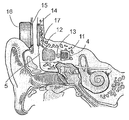
- FIG. 3 a shows that the implantable housing ( 12 ) containing the transducer also has a protective encasement of for example silicon ( 18 ) with the exception of a protrusion ( 19 ) in the medial direction.
- This protrusion ( 19 ) has a biocompatible attachment surface ( 20 ) which will be attached to the skull bone for the transmission of signal vibrations.
- the biocompatible attachment surface ( 20 ) stretches across the transversal surface and the protrusion neck ( 19 ) as is indicated in FIG. 2 a.
- the attachment surface ( 20 ) of the transducer housing can have an arbitrary shape and cross section i.e. rectangular or round for example. Its size can range from a few mm 2 up to the entire cross section surface of the transducer housing, as is shown in the detail of FIG. 3 b .
- the fixation in an axial direction is not critical as long as the F force is maintained, which also allows for easy removal of the transducer housing.
- the appropriate healing period has elapsed, it is likely that the requirement on the contact force's F's size can be diminished. This is provided by a tight and moist attachment surface giving a rigid attachment in the same way as for example in a joint where the bone conduction vibrations can be transmitted without significant losses.
- FIG. 3 a is also shown how the protective encasement ( 18 ) has an outgrowth of elastic material such as silicone ( 21 ) in a lateral direction with suitable elastic properties.
- the elastic outgrowth ( 21 ) can contain one or more air cells ( 22 ) and can stretch across the entire lateral side of the transducer housing.
- FIG. 3 b shows how the fixation, between the biocompatible surface of the housing ( 20 ) and the bottom plane ( 4 ), are created in this preferred embodiment by having a bar plate ( 23 ) with holder ears ( 24 ) and with the aid of fastening screws ( 25 ) compressing the elastic encasement ( 18 ) and/or the elastic outgrowth ( 21 ) in a medial direction and against the bottom plane thus creating the force F.
- FIG. 23 shows how the fixation, between the biocompatible surface of the housing ( 20 ) and the bottom plane ( 4 ), are created in this preferred embodiment by having a bar plate ( 23 ) with holder ears ( 24 ) and with the aid of fastening
- FIG. 3 c shows that the implanted and encased transducer has a receiving coil ( 14 ) electrically connected and contained in a prolonged part ( 27 ) of the encasement ( 18 ). There is an electronic unit ( 28 ) with appropriate demodulation electronics and power electronics between the receiving coil ( 14 ) and the transducer.
- the electronic components can be integrated inside the transducer housing or in the receiving coil or between these two (only the last alternative is shown in FIG. 3 c ).
- FIG. 3 d shows the externally supported sound processor ( 16 ) which contains the transmitting coil ( 15 ).
- the sound processor ( 16 ) contains common hearing aid components such as one or more microphones ( 29 ), a signal processing unit ( 30 ), and battery ( 31 ).
- one or more magnets ( 32 a, b ) are placed centrally in the transmitting coil and the receiving coil, respectively.
- FIG. 4 shows how the bottom plane ( 4 ) can be prepared with the help of a biocompatible intermediate layer ( 33 ) between the bottom plane ( 4 ) and the attachment surface of the housing ( 20 ).
- the intermediate layer ( 33 ) can consist of bone chips or bone cement or another bone substitute such as Hydroxyl apatite (HA).
- a bone implant can also be taken from the outer compact layer of bone when the recess ( 5 ) is made. This compact bone transplant can then be adapted for use as the intermediate layer ( 33 ) allowing for a stable connection to the temporal bone with the individual's own compact bone tissue.
- FIG. 5 a shows an alternative method to attach the transducer house by use of elastic metallic wire elements ( 34 ), where their ends ( 35 a, b ) can be tightened and attached to the groove ( 36 a, b ) under the temporal bone's outer wall of compact bone ( 10 ).
- the thread element can be suitably joined in the middle part ( 37 ) by spot welding, for example, so that they create an H-form.
- Tracks can be formed in the encasement ( 18 ) and/or in its protrusion ( 21 ) in order to attach the wire element (not shown in FIGS. 5 a, b ).
- one side of the wire ends ( 35 b ) can first be put in the groove ( 36 b ).
- the two other free wire ends ( 35 a ) are then pressed together (shown as a broken line in FIG. 5 b ) and thereafter placed through an opening ( 38 ) in the compact bone wall in order to then be secured in the groove ( 36 a ).
- FIG. 6 a shows another, simpler, preferred embodiment entailing that the wire elements ( 34 ) are substituted by suture threads ( 39 ).
- the suture threads are tied or attached through holes ( 40 ) in the outer bone that enters in the grooves ( 36 ).
- FIG. 6 b shows that the contact force F is effected partly because the suture threads ( 39 ) are tightened over the encasement of the transducer housing ( 18 ) and because the periosteum ( 41 ) as well as the soft tissue ( 42 ) and outer skin ( 43 ) are sutured with a pressure acting in the medial direction against the implanted transducer housing.
- the transducer's housing can be stabilized in the recess ( 5 ) with e.g. fat tissue ( 44 ) so that it will not move in a transversal (radial) direction. Such stabilization can be desirable in all of the models described above.
- FIG. 7 shows how the static force can be generated with the help of a biocompatible screw based tightening device with arms ( 45 ) which attach against the temporal bone's compact outer bone wall ( 10 ) from the groove ( 36 ) in lateral direction.
- the attachment is made with a screw adjustment ( 46 ) which is put through a holder seat ( 47 ) integrated in the transducer housing ( 12 ) and which can press the arms ( 45 ) outward to maintain the force F with the aid of a screw driver ( 48 ).
- FIGS. 8 a - d shows an embodiment where an adaptor ( 49 ) of bio compatible material is placed between the bone on the bottom plane ( 4 ) and the transducer housing's attachment surface ( 20 ).
- FIG. 8 b shows how the adaptor ( 49 ) can have protruding elastic arms ( 50 ) for static coupling to the transducer housing ( 12 ) and for the transmission of the vibrations.
- the elastic arms can have a thinner cross section than the bottom plane.
- the protrusion ( 19 ) of the transducer housing can have indents ( 51 ) adapted to the elastic arms ( 50 ) so that these elastic arms ( 50 ) will be able to grip firmly to the housing.
- FIG. 8 c shows how the adaptor ( 49 ) can have holes ( 52 ) in the plate to facilitate in growth of the bone tissue and in FIG. 8 d it is shown that the adaptor ( 49 ) can be circular.
- FIG. 9 shows a preferred embodiment where the adaptor ( 49 ) is pressed into a groove ( 53 ) in the bone of the bottom plane ( 4 ) where transversal forces F2 are built up which are strong enough to anchor the adaptor in the lateral-medial (axial) direction so that the signal forces can be transmitted from the housing ( 12 ) to the skull bone without distortion.
Landscapes
- Health & Medical Sciences (AREA)
- General Health & Medical Sciences (AREA)
- Otolaryngology (AREA)
- Neurosurgery (AREA)
- Physics & Mathematics (AREA)
- Engineering & Computer Science (AREA)
- Acoustics & Sound (AREA)
- Signal Processing (AREA)
- Details Of Audible-Bandwidth Transducers (AREA)
- Prostheses (AREA)
Applications Claiming Priority (3)
| Application Number | Priority Date | Filing Date | Title |
|---|---|---|---|
| SE0800390 | 2008-02-20 | ||
| SE0800390-7 | 2008-02-20 | ||
| SE0800390A SE533430C2 (sv) | 2008-02-20 | 2008-02-20 | Implanterbar vibrator |
Publications (2)
| Publication Number | Publication Date |
|---|---|
| US20090209806A1 US20090209806A1 (en) | 2009-08-20 |
| US8241201B2 true US8241201B2 (en) | 2012-08-14 |
Family
ID=40651702
Family Applications (1)
| Application Number | Title | Priority Date | Filing Date |
|---|---|---|---|
| US12/388,618 Active 2030-11-15 US8241201B2 (en) | 2008-02-20 | 2009-02-19 | Implantable transducer |
Country Status (4)
| Country | Link |
|---|---|
| US (1) | US8241201B2 (de) |
| EP (1) | EP2094029B1 (de) |
| DK (1) | DK2094029T3 (de) |
| SE (1) | SE533430C2 (de) |
Cited By (6)
| Publication number | Priority date | Publication date | Assignee | Title |
|---|---|---|---|---|
| US20120029267A1 (en) * | 2010-06-21 | 2012-02-02 | Vibrant Med-El Hearing Technology Gmbh | Electromagnetic Bone Conduction Hearing Device |
| US20130035540A1 (en) * | 2009-07-22 | 2013-02-07 | Vibrant Med-El Hearing Technology Gmbh | Electromagnetic Bone Conduction Hearing Device |
| WO2017136619A1 (en) | 2016-02-05 | 2017-08-10 | Med-El Elektromedizinische Geraete Gmbh | Variable transducer fixation |
| US20170257710A1 (en) * | 2008-03-31 | 2017-09-07 | Cochlear Limited | Bone conduction device |
| CN107427363A (zh) * | 2015-03-18 | 2017-12-01 | Med-El电气医疗器械有限公司 | 骨传导漂浮质量传感器的固定 |
| US11012797B2 (en) * | 2015-12-16 | 2021-05-18 | Cochlear Limited | Bone conduction device having magnets integrated with housing |
Families Citing this family (42)
| Publication number | Priority date | Publication date | Assignee | Title |
|---|---|---|---|---|
| WO2010142018A1 (en) | 2009-06-09 | 2010-12-16 | Dalhousie University | Subcutaneous piezoelectric bone conduction hearing aid actuator and system |
| US8965021B2 (en) | 2009-06-09 | 2015-02-24 | Dalhousie University | Subcutaneous piezoelectric bone conduction hearing aid actuator and system |
| US8565461B2 (en) | 2011-03-16 | 2013-10-22 | Cochlear Limited | Bone conduction device including a balanced electromagnetic actuator having radial and axial air gaps |
| US20130096366A1 (en) * | 2011-10-12 | 2013-04-18 | Wim Bervoets | Implantable medical device |
| EP2592848B1 (de) | 2011-11-08 | 2019-06-26 | Oticon Medical A/S | Akustisches Übertragungsverfahren und Hörvorrichtung |
| US8897475B2 (en) | 2011-12-22 | 2014-11-25 | Vibrant Med-El Hearing Technology Gmbh | Magnet arrangement for bone conduction hearing implant |
| US11641552B2 (en) | 2011-12-23 | 2023-05-02 | Shenzhen Shokz Co., Ltd. | Bone conduction speaker and compound vibration device thereof |
| US11665482B2 (en) | 2011-12-23 | 2023-05-30 | Shenzhen Shokz Co., Ltd. | Bone conduction speaker and compound vibration device thereof |
| US11641551B2 (en) | 2011-12-23 | 2023-05-02 | Shenzhen Shokz Co., Ltd. | Bone conduction speaker and compound vibration device thereof |
| US11611834B2 (en) | 2011-12-23 | 2023-03-21 | Shenzhen Shokz Co., Ltd. | Bone conduction speaker and compound vibration device thereof |
| US11638099B2 (en) | 2011-12-23 | 2023-04-25 | Shenzhen Shokz Co., Ltd. | Bone conduction speaker and compound vibration device thereof |
| US20130165737A1 (en) * | 2011-12-23 | 2013-06-27 | Koen Van den Heuvel | Implantation of a hearing prosthesis |
| US11601761B2 (en) | 2011-12-23 | 2023-03-07 | Shenzhen Shokz Co., Ltd. | Bone conduction speaker and compound vibration device thereof |
| US11716575B2 (en) | 2011-12-23 | 2023-08-01 | Shenzhen Shokz Co., Ltd. | Bone conduction speaker and compound vibration device thereof |
| US11528562B2 (en) | 2011-12-23 | 2022-12-13 | Shenzhen Shokz Co., Ltd. | Bone conduction speaker and compound vibration device thereof |
| US11540057B2 (en) | 2011-12-23 | 2022-12-27 | Shenzhen Shokz Co., Ltd. | Bone conduction speaker and compound vibration device thereof |
| US11463814B2 (en) | 2011-12-23 | 2022-10-04 | Shenzhen Shokz Co., Ltd. | Bone conduction speaker and compound vibration device thereof |
| US11595760B2 (en) | 2011-12-23 | 2023-02-28 | Shenzhen Shokz Co., Ltd. | Bone conduction speaker and compound vibration device thereof |
| US11399234B2 (en) | 2011-12-23 | 2022-07-26 | Shenzhen Shokz Co., Ltd. | Bone conduction speaker and compound vibration device thereof |
| US11483661B2 (en) | 2011-12-23 | 2022-10-25 | Shenzhen Shokz Co., Ltd. | Bone conduction speaker and compound vibration device thereof |
| US11575994B2 (en) | 2011-12-23 | 2023-02-07 | Shenzhen Shokz Co., Ltd. | Bone conduction speaker and compound vibration device thereof |
| EP2870781B1 (de) | 2012-07-09 | 2019-05-01 | Med-El Elektromedizinische Geräte GmbH | Elektromagnetische knochenleitungshörvorrichtung |
| US20140163626A1 (en) | 2012-12-12 | 2014-06-12 | Grahame Walling | Implantable device migration control |
| AU2014225919B2 (en) * | 2013-03-07 | 2017-02-16 | Med-El Elektromedizinische Geraete Gmbh | Implant fixation and impact displacement protection systems |
| US9716953B2 (en) | 2013-03-15 | 2017-07-25 | Cochlear Limited | Electromagnetic transducer with specific internal geometry |
| US9980064B2 (en) * | 2013-09-30 | 2018-05-22 | Cochlear Limited | Sub-cranial vibratory stimulator |
| US11412334B2 (en) | 2013-10-23 | 2022-08-09 | Cochlear Limited | Contralateral sound capture with respect to stimulation energy source |
| US12464299B2 (en) | 2014-01-06 | 2025-11-04 | Shenzhen Shokz Co., Ltd. | Systems and methods for suppressing sound leakage |
| US12532132B2 (en) | 2014-01-06 | 2026-01-20 | Shenzhen Shokz Co., Ltd. | Systems and methods for suppressing sound leakage |
| US11368800B2 (en) | 2014-01-06 | 2022-06-21 | Shenzhen Shokz Co., Ltd. | Systems and methods for suppressing sound leakage |
| US11375324B2 (en) | 2014-01-06 | 2022-06-28 | Shenzhen Shokz Co., Ltd. | Systems and methods for suppressing sound leakage |
| US11363392B2 (en) | 2014-01-06 | 2022-06-14 | Shenzhen Shokz Co., Ltd. | Systems and methods for suppressing sound leakage |
| US12413915B2 (en) | 2014-01-06 | 2025-09-09 | Shenzhen Shokz Co., Ltd. | Systems and methods for suppressing sound leakage |
| US11418895B2 (en) | 2014-01-06 | 2022-08-16 | Shenzhen Shokz Co., Ltd. | Systems and methods for suppressing sound leakage |
| US12483842B2 (en) | 2014-01-06 | 2025-11-25 | Shenzhen Shokz Co., Ltd. | Systems and methods for suppressing sound leakage |
| US11368801B2 (en) | 2014-01-06 | 2022-06-21 | Shenzhen Shokz Co., Ltd. | Systems and methods for suppressing sound leakage |
| US20150382114A1 (en) * | 2014-06-25 | 2015-12-31 | Marcus ANDERSSON | System for adjusting magnetic retention force in auditory prostheses |
| US10609496B2 (en) * | 2015-08-13 | 2020-03-31 | Shenzhen Voxtech Co., Ltd. | Systems for bone conduction speaker |
| US11368802B2 (en) * | 2016-04-27 | 2022-06-21 | Cochlear Limited | Implantable vibratory device using limited components |
| EP3404933A1 (de) | 2017-05-15 | 2018-11-21 | Oticon Medical A/S | Hörgerät zur platzierung im ohr eines benutzers |
| US11035830B2 (en) | 2017-06-23 | 2021-06-15 | Cochlear Limited | Electromagnetic transducer with dual flux |
| US11778385B2 (en) | 2017-06-23 | 2023-10-03 | Cochlear Limited | Electromagnetic transducer with non-axial air gap |
Citations (13)
| Publication number | Priority date | Publication date | Assignee | Title |
|---|---|---|---|---|
| US4498461A (en) | 1981-12-01 | 1985-02-12 | Bo Hakansson | Coupling to a bone-anchored hearing aid |
| US4612915A (en) | 1985-05-23 | 1986-09-23 | Xomed, Inc. | Direct bone conduction hearing aid device |
| US4652702A (en) | 1983-11-09 | 1987-03-24 | Ken Yoshii | Ear microphone utilizing vocal bone vibration and method of manufacture thereof |
| US4904233A (en) | 1985-05-10 | 1990-02-27 | Haakansson Bo | Arrangement in a hearing aid device |
| WO2001045457A2 (en) | 1999-12-16 | 2001-06-21 | John Nicholas Marshall | Implantable hearing aid 1.1 |
| WO2004014269A1 (en) | 2002-08-09 | 2004-02-19 | Cochlear Limited | Fixation system for an implantable medical device |
| US20040032962A1 (en) * | 2000-06-02 | 2004-02-19 | Patrik Westerkull | Bone conducting hearing aid |
| WO2004084583A1 (ja) | 2003-03-19 | 2004-09-30 | National Institute Of Advanced Industrial Science And Technology | 補聴器および生体振動子 |
| US20070053542A1 (en) | 2005-09-08 | 2007-03-08 | Dong-Won Lee | Bone conduction speaker |
| US20070156011A1 (en) * | 2006-01-02 | 2007-07-05 | Patrik Westerkull | Hearing aid system |
| US20070191673A1 (en) | 2006-02-14 | 2007-08-16 | Vibrant Med-El Hearing Technology Gmbh | Bone conductive devices for improving hearing |
| US20080312716A1 (en) * | 2005-06-16 | 2008-12-18 | Russell Michael J | Methods and Systems for Using Intracranial Electrodes |
| US8065012B2 (en) * | 2000-07-13 | 2011-11-22 | Advanced Neuromodulation Systems, Inc. | Methods and apparatus for effectuating a lasting change in a neural-function of a patient |
Family Cites Families (2)
| Publication number | Priority date | Publication date | Assignee | Title |
|---|---|---|---|---|
| US5897486A (en) | 1993-07-01 | 1999-04-27 | Symphonix Devices, Inc. | Dual coil floating mass transducers |
| US5554096A (en) | 1993-07-01 | 1996-09-10 | Symphonix | Implantable electromagnetic hearing transducer |
-
2008
- 2008-02-20 SE SE0800390A patent/SE533430C2/sv unknown
-
2009
- 2009-02-19 EP EP09153215.0A patent/EP2094029B1/de active Active
- 2009-02-19 US US12/388,618 patent/US8241201B2/en active Active
- 2009-02-19 DK DK09153215.0T patent/DK2094029T3/da active
Patent Citations (15)
| Publication number | Priority date | Publication date | Assignee | Title |
|---|---|---|---|---|
| US4498461A (en) | 1981-12-01 | 1985-02-12 | Bo Hakansson | Coupling to a bone-anchored hearing aid |
| US4652702A (en) | 1983-11-09 | 1987-03-24 | Ken Yoshii | Ear microphone utilizing vocal bone vibration and method of manufacture thereof |
| US4904233A (en) | 1985-05-10 | 1990-02-27 | Haakansson Bo | Arrangement in a hearing aid device |
| US4612915A (en) | 1985-05-23 | 1986-09-23 | Xomed, Inc. | Direct bone conduction hearing aid device |
| WO2001045457A2 (en) | 1999-12-16 | 2001-06-21 | John Nicholas Marshall | Implantable hearing aid 1.1 |
| US20040032962A1 (en) * | 2000-06-02 | 2004-02-19 | Patrik Westerkull | Bone conducting hearing aid |
| US8065012B2 (en) * | 2000-07-13 | 2011-11-22 | Advanced Neuromodulation Systems, Inc. | Methods and apparatus for effectuating a lasting change in a neural-function of a patient |
| WO2004014269A1 (en) | 2002-08-09 | 2004-02-19 | Cochlear Limited | Fixation system for an implantable medical device |
| WO2004084583A1 (ja) | 2003-03-19 | 2004-09-30 | National Institute Of Advanced Industrial Science And Technology | 補聴器および生体振動子 |
| US20080312716A1 (en) * | 2005-06-16 | 2008-12-18 | Russell Michael J | Methods and Systems for Using Intracranial Electrodes |
| US20070053542A1 (en) | 2005-09-08 | 2007-03-08 | Dong-Won Lee | Bone conduction speaker |
| US20070156011A1 (en) * | 2006-01-02 | 2007-07-05 | Patrik Westerkull | Hearing aid system |
| WO2007078506A2 (en) | 2006-01-02 | 2007-07-12 | Oticon A/S | Hearing aid system |
| US20070191673A1 (en) | 2006-02-14 | 2007-08-16 | Vibrant Med-El Hearing Technology Gmbh | Bone conductive devices for improving hearing |
| WO2007095196A2 (en) | 2006-02-14 | 2007-08-23 | Vibrant Med-El Hearing Technology Gmbh | Bone conductive devices for improving hearing |
Non-Patent Citations (1)
| Title |
|---|
| The European Search Report issued in connection with EP Application No. 09153215.0 mailed on Oct. 7, 2010. |
Cited By (12)
| Publication number | Priority date | Publication date | Assignee | Title |
|---|---|---|---|---|
| US20170257710A1 (en) * | 2008-03-31 | 2017-09-07 | Cochlear Limited | Bone conduction device |
| US11570552B2 (en) * | 2008-03-31 | 2023-01-31 | Cochlear Limited | Bone conduction device |
| US20130035540A1 (en) * | 2009-07-22 | 2013-02-07 | Vibrant Med-El Hearing Technology Gmbh | Electromagnetic Bone Conduction Hearing Device |
| US8774930B2 (en) * | 2009-07-22 | 2014-07-08 | Vibrant Med-El Hearing Technology Gmbh | Electromagnetic bone conduction hearing device |
| US20120029267A1 (en) * | 2010-06-21 | 2012-02-02 | Vibrant Med-El Hearing Technology Gmbh | Electromagnetic Bone Conduction Hearing Device |
| CN107427363A (zh) * | 2015-03-18 | 2017-12-01 | Med-El电气医疗器械有限公司 | 骨传导漂浮质量传感器的固定 |
| EP3270823A4 (de) * | 2015-03-18 | 2018-03-21 | MED-EL Elektromedizinische Geraete GmbH | Befestigung eines knochenleitenden schwimmenden massenumwandlers |
| AU2016233286B2 (en) * | 2015-03-18 | 2018-09-27 | Med-El Elektromedizinische Geraete Gmbh | Fixation of a bone conduction floating mass transducer |
| AU2016233286C1 (en) * | 2015-03-18 | 2019-03-14 | Med-El Elektromedizinische Geraete Gmbh | Fixation of a bone conduction floating mass transducer |
| US10616698B2 (en) | 2015-03-18 | 2020-04-07 | Med-El Elektromedizinische Geraete Gmbh | Fixation of a bone conduction floating mass transducer |
| US11012797B2 (en) * | 2015-12-16 | 2021-05-18 | Cochlear Limited | Bone conduction device having magnets integrated with housing |
| WO2017136619A1 (en) | 2016-02-05 | 2017-08-10 | Med-El Elektromedizinische Geraete Gmbh | Variable transducer fixation |
Also Published As
| Publication number | Publication date |
|---|---|
| EP2094029B1 (de) | 2014-04-09 |
| US20090209806A1 (en) | 2009-08-20 |
| SE0800390L (sv) | 2009-08-21 |
| DK2094029T3 (da) | 2014-07-07 |
| SE533430C2 (sv) | 2010-09-28 |
| EP2094029A3 (de) | 2010-11-10 |
| EP2094029A2 (de) | 2009-08-26 |
Similar Documents
| Publication | Publication Date | Title |
|---|---|---|
| US8241201B2 (en) | Implantable transducer | |
| US6488616B1 (en) | Hearing aid transducer support | |
| Goode et al. | The history and development of the implantable hearing aid | |
| US5015224A (en) | Partially implantable hearing aid device | |
| US4957478A (en) | Partially implantable hearing aid device | |
| US6171229B1 (en) | Ossicular transducer attachment for an implantable hearing device | |
| US8105229B2 (en) | At least partially implantable hearing system | |
| US5277694A (en) | Electromechanical transducer for implantable hearing aids | |
| AU5797101A (en) | At least partially implantable hearing system for rehabilitation of a hearing disorder | |
| US6267731B1 (en) | Method and apparatus for reduced feedback in implantable hearing assistance systems | |
| Maniglia et al. | Electromagnetic implantable middle ear hearing device of the ossicular-stimulating type: principles, designs, and experiments | |
| US20130018217A1 (en) | Clover Shape Attachment for Implantable Floating Mass Transducer | |
| AU2019282656B2 (en) | Passive hearing implant | |
| US7297101B2 (en) | Method and apparatus for minimally invasive placement of sensing and driver assemblies to improve hearing loss | |
| Zenner et al. | Totally Implantable Active Middle Ear Implants: Ten Years’ Experience at the | |
| Håkansson | The future of bone conduction hearing devices | |
| US11425514B2 (en) | Universal bone conduction and middle ear implant | |
| Winter et al. | The use of reverse transfer function (RTF) in the fitting procedure of implantable hearing devices | |
| LEE et al. | Bone-Conduction Hearing Devices | |
| SLATTERY III | Implantable hearing devices | |
| Kuhn et al. | 32 Implantable Hearing Devices |
Legal Events
| Date | Code | Title | Description |
|---|---|---|---|
| AS | Assignment |
Owner name: OSSEOFON AB, SWEDEN Free format text: ASSIGNMENT OF ASSIGNORS INTEREST;ASSIGNOR:HAKANSSON, BO;REEL/FRAME:022540/0449 Effective date: 20090330 |
|
| STCF | Information on status: patent grant |
Free format text: PATENTED CASE |
|
| FEPP | Fee payment procedure |
Free format text: PAT HOLDER CLAIMS SMALL ENTITY STATUS, ENTITY STATUS SET TO SMALL (ORIGINAL EVENT CODE: LTOS); ENTITY STATUS OF PATENT OWNER: LARGE ENTITY |
|
| FEPP | Fee payment procedure |
Free format text: PAT HOLDER NO LONGER CLAIMS SMALL ENTITY STATUS, ENTITY STATUS SET TO UNDISCOUNTED (ORIGINAL EVENT CODE: STOL); ENTITY STATUS OF PATENT OWNER: LARGE ENTITY |
|
| FPAY | Fee payment |
Year of fee payment: 4 |
|
| MAFP | Maintenance fee payment |
Free format text: PAYMENT OF MAINTENANCE FEE, 8TH YEAR, LARGE ENTITY (ORIGINAL EVENT CODE: M1552); ENTITY STATUS OF PATENT OWNER: LARGE ENTITY Year of fee payment: 8 |
|
| MAFP | Maintenance fee payment |
Free format text: PAYMENT OF MAINTENANCE FEE, 12TH YEAR, LARGE ENTITY (ORIGINAL EVENT CODE: M1553); ENTITY STATUS OF PATENT OWNER: LARGE ENTITY Year of fee payment: 12 |