US8306761B2 - Apparatus and method for identifying the position of defects in bodies, in particular in wooden bodies such as logs or planks - Google Patents
Apparatus and method for identifying the position of defects in bodies, in particular in wooden bodies such as logs or planks Download PDFInfo
- Publication number
- US8306761B2 US8306761B2 US12/552,388 US55238809A US8306761B2 US 8306761 B2 US8306761 B2 US 8306761B2 US 55238809 A US55238809 A US 55238809A US 8306761 B2 US8306761 B2 US 8306761B2
- Authority
- US
- United States
- Prior art keywords
- beams
- feed
- defect
- emitter
- identifying
- Prior art date
- Legal status (The legal status is an assumption and is not a legal conclusion. Google has not performed a legal analysis and makes no representation as to the accuracy of the status listed.)
- Active, expires
Links
Images



Classifications
-
- G—PHYSICS
- G01—MEASURING; TESTING
- G01N—INVESTIGATING OR ANALYSING MATERIALS BY DETERMINING THEIR CHEMICAL OR PHYSICAL PROPERTIES
- G01N33/00—Investigating or analysing materials by specific methods not covered by groups G01N1/00 - G01N31/00
- G01N33/46—Wood
-
- G—PHYSICS
- G01—MEASURING; TESTING
- G01N—INVESTIGATING OR ANALYSING MATERIALS BY DETERMINING THEIR CHEMICAL OR PHYSICAL PROPERTIES
- G01N23/00—Investigating or analysing materials by the use of wave or particle radiation, e.g. X-rays or neutrons, not covered by groups G01N3/00 – G01N17/00, G01N21/00 or G01N22/00
- G01N23/02—Investigating or analysing materials by the use of wave or particle radiation, e.g. X-rays or neutrons, not covered by groups G01N3/00 – G01N17/00, G01N21/00 or G01N22/00 by transmitting the radiation through the material
- G01N23/06—Investigating or analysing materials by the use of wave or particle radiation, e.g. X-rays or neutrons, not covered by groups G01N3/00 – G01N17/00, G01N21/00 or G01N22/00 by transmitting the radiation through the material and measuring the absorption
- G01N23/083—Investigating or analysing materials by the use of wave or particle radiation, e.g. X-rays or neutrons, not covered by groups G01N3/00 – G01N17/00, G01N21/00 or G01N22/00 by transmitting the radiation through the material and measuring the absorption the radiation being X-rays
Definitions
- the present invention relates to an apparatus and a method for identifying the position of defects, such as knots, cracks or cavities, in wooden bodies such as logs or planks.
- a first type of apparatus comprises two electromagnetic radiation emitters placed at a right angle to each other (usually one horizontal and one vertical) and lying in a plane which is perpendicular to a longitudinal axis of the log or plank, and also comprises two sensors positioned in such a way that each sensor receives the radiation emitted by one of the two emitters after it has passed through the wood.
- a second type of detection apparatus comprises a single emitter and a plurality of sensors aligned along a direction perpendicular to the longitudinal axis of the wooden log or plank (said longitudinal axis usually coincides with a log or plank feed direction) for detecting the intensity of the radiation emitted by the emitter after it has passed through the wood.
- the emitter generates a beam of electromagnetic radiation with a diverging shape, that is to say, its size increasing from the emitter towards the sensors, thus allowing the radiation emitted to cover all of the sensors.
- the analysis of the intensity of the radiation detected by each sensor allows identification of which sensors encountered an abnormal intensity and, therefore, the position where the defect in the wood is located.
- a third type of detection apparatus comprises a portal through which the log or plank to be analysed is passed.
- On the portal which is positioned perpendicularly to the longitudinal axis of the log or plank, there are two emitters generating respective diverging beams. The emitters are set at an angle to each other, so that the same points of the log or plank are struck from two different angles and therefore the defect is “observed” form two different points.
- the sensors are aligned in a row positioned perpendicularly to the longitudinal axis of the log and are located below the portal.
- the apparatuses of the first type described above usually require the log or plank to be held stationary during the detection step, having a significant negative impact on the productivity of the plants in which such apparatuses are included.
- the apparatuses of the first type require the use of two emitters which, as is well known, are amongst the most expensive components of a detection plant and therefore have a negative impact on plant production costs.
- Detection apparatuses of the second type only have one emitter, but the information that it can provide is not sufficient to correctly identify the position in space of defects in the log or plank detected.
- Each sensor measures an intensity of radiation received and, if abnormal values are measured, it means that there is a defect in the wood between the emitter and that sensor.
- apparatuses of the second type cannot provide any information about the distance separating the defect from the emitter or from the sensor, since whatever the distance between the defect and the emitter or the sensor along a line linking them, the intensity detected by the sensor would be the same.
- Apparatuses of the third type similarly to those of the first type, have the disadvantage of requiring the use of two emitters, consequently increasing plant costs.
- the technical purpose of the present invention is to provide an apparatus and a method for identifying the position of defects in bodies, in particular in wooden bodies such as logs or planks, which overcomes the above-mentioned disadvantages.
- the present invention has for an aim to provide an apparatus and a method for identifying the position of defects in bodies, in particular in wooden bodies such as logs or planks, which allows precise identification of the three-dimensional position of any defects whilst at the same time keeping plant costs down.
- FIG. 1 is a schematic perspective view of the apparatus according to the present invention during a log analysis step
- FIG. 2 is a schematic perspective view of the apparatus according to the present invention during a wooden plank analysis step
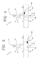
- FIGS. 3 and 4 are schematic cross-sections of the apparatus of FIG. 2 according to different operating situations.
- FIG. 5 is a cross-section of a numerical reconstruction of a portion of a wooden body according to the method disclosed by the present invention.
- the numeral 1 denotes as a whole an apparatus for identifying the position of defects, such as knots, cracks or cavities, in bodies 2 , in particular in wooden bodies 2 such as logs or planks.
- FIG. 1 shows the apparatus 1 while it is acting on a body 2 in the form of a log, whilst in FIG. 2 the body 2 analysed is a wooden plank.
- the apparatus 1 comprises body 2 feed means 3 for moving the body 2 along a feed direction “A” which is preferably horizontal.
- the feed means 3 comprise a plurality of rollers 4 connected to motor means, not illustrated, for pulling the body 2 along the feed direction “A”.
- the feed direction “A” coincides with a main direction of extension X of the body 2 .
- the apparatus 1 also comprises an emitter 5 for emitting a plurality of beams 6 ′, 6 ′′, 6 ′′′ of electromagnetic radiation.
- the emitter 5 is an X-ray emitter.
- the beams 6 ′, 6 ′′, 6 ′′′ lie in respective lying planes “P 1 ”, “P 2 ”′, “P 3 ” extending from the emitter 5 and intersecting the body 2 which is opposite the emitter 5 .
- the emitter 5 is of the type able to generate beams 6 ′, 6 ′′, 6 ′′′ according to respective lying planes “P 1 ”, “P 2 ”′, “P 3 ” which are set at different angles to the feed direction “A”.
- each of the lying planes “P 1 ”, “P 2 ”′, “P 3 ” is set at a different angle relative to the other lying planes “P 1 ”, “P 2 ”′, “P 3 ” for intersecting the body 2 both at different points of the body 2 and according to different directions.
- the emitter 5 generates a plurality of beams 6 ′, 6 ′′, 6 ′′′ diverging from each other away from the emitter 5 towards the body 2 .
- Each beam 6 ′, 6 ′′, 6 ′′′ is preferably sized so that it strikes an entire transversal dimension of the body 2 , said transversal dimension being perpendicular to the feed direction “A”, in particular horizontal.
- the central lying plane 6 ′′ is substantially perpendicular to the feed direction “A”, more precisely it is vertical.
- the other lying planes “P 1 ”, “P 3 ” are set at an angle “G” to each other, forming a maximum flare angle for the emitter 5 electromagnetic emission.
- the angle “G” is preferably less than or equal to 90 degrees.
- FIGS. 1 and 2 show, labelled 7 ′, 7 ′′, 7 ′′′, the cross-sections of the body 2 identified by the intersection between the beams 6 ′, 6 ′′, 6 ′′′ and the body 2 .
- Said cross-sections 7 ′, 7 ′′, 7 ′′′ are highlighted with dense background to highlight the different angles of the cross-sections 7 ′, 7 ′′, 7 ′′′ caused by the different angles of the lying planes “P 1 ”, “P 2 ”′, “P 3 ”.
- the emitter 5 is positioned above the body 2 to be analysed.
- the apparatus 1 also comprises, on the opposite side of the body 2 relative to the emitter 5 , that is to say, below the body 2 , a plurality of sensors 8 ′, 8 ′′, 8 ′′′ whose number is preferably the same as the number of beams 6 ′, 6 ′′, 6 ′′′.
- Each sensor 8 ′, 8 ′′, 8 ′′′ is designed to receive a respective beam 6 ′, 6 ′′, 6 ′′′ of electromagnetic radiation after the beam 6 ′, 6 ′′, 6 ′′′ has passed through the body 2 .
- each sensor 8 ′, 8 ′′, 8 ′′′ can measure a residual intensity of the respective beam 6 ′, 6 ′′, 6 ′′′ to identify how much energy the beam 6 ′, 6 ′′, 6 ′′′ lost as it passed through the body 2 .
- the analysis of the energy absorbed by the body 2 in each of the cross-sections 7 ′, 7 ′′, 7 ′′′ allows evaluation of the existence of a defect in one or more of the cross-sections 7 ′, 7 ′′, 7 ′′′, since the presence of defects distorts the energy absorption values, making them greater than or less than an expected normal value, characteristic of wood which is free of defects.
- the apparatus 1 also comprises a processing unit, not illustrated, connected to the sensors 8 ′, 8 ′′, 8 ′′′ and preferably also to the emitter 5 for receiving the intensity values of the beams 6 ′, 6 ′′, 6 ′′′ emitted by the emitter 5 and detected by the sensors 8 ′, 8 ′′, 8 ′′′.
- the processing unit can also store said data and associate it with a relative moment in time in which it was detected, allowing subsequent processing of the data, even complex processing, as described below.
- FIGS. 3 and 4 help to explain the operating principle of the apparatus 1 described above.
- the body 2 is then conveyed, by the feed means 3 , through a space “S” between the emitter 5 and the sensors 8 ′, 8 ′′, 8 ′′′ and is fed along the feed direction “A”.
- the body 2 is fed with a known feed speed which is preferably kept constant at least during an entire body 2 detection step.
- FIG. 3 shows a situation in which the defect 100 is located in a lower portion of the body 2 , and shows the moment when the defect 100 encounters the central beam 6 ′′.
- the defect 100 is illustrated with a light line, whilst again in FIG. 3 the same defect is labelled 200 at the moment when it reaches the last beam 6 ′′′.
- Each sensor 8 ′, 8 ′′, 8 ′′′ detects a continuous succession of residual intensity values of each beam 6 ′, 6 ′′, 6 ′′′ which emerges from the body 2 .
- each sensor 8 ′, 8 ′′, 8 ′′′ detects a succession of residual intensity values of each beam 6 ′, 6 ′′, 6 ′′′ at moments which are close together, so as to detect, with predetermined precision, when a defect 100 is close to the respective beam 6 ′, 6 ′′, 6 ′′′ detected.
- the processing unit Since at the moment when a defect encounters a beam of electromagnetic radiation it modifies a beam energy absorption which is instantaneously detected by the sensor, which sends a corresponding signal to the processing unit, the processing unit is always able to recognise whether or not at a predetermined moment a defect 100 is passing through one of the beams. Therefore, at the moment when the defect 100 encounters the central beam 6 ′′, the respective central sensor 8 ′′ detects a residual intensity value in the beam 6 ′′ detected. The processing unit receives from the sensor 8 ′′ a signal identifying the abnormal energy absorption and, therefore, identifies the existence of a defect 100 passing through the central beam 6 ′′.
- the defect 100 reaches the last beam 6 ′′′, reaching the configuration shown in FIG. 3 in which the defect is labelled 200 and shown with a thick line.
- the last sensor 8 ′′′ detects an abnormal residual intensity value in the last beam 6 ′′′ and this is associated with an abnormal energy absorption in that beam 6 ′′′ and, therefore, linked to a defect 200 passing through the last beam 6 ′′′.
- the processing unit can identify a distance “L 1 ” travelled by the defect 100 between the central beam 6 ′′ and the last beam 6 ′′′. Once said distance travelled “L 1 ” information has been obtained, and knowing the geometry of the planes “P 1 ”, “P 2 ”′, “P 3 ” in which the beams 6 ′, 6 ′′, 6 ′′′ lie, the processing unit can unambiguously evaluate the vertical position of the defect 100 , that is to say, the position of the defect 100 along a direction linking the emitter 5 with one of the sensors 8 ′, 8 ′′, 8 ′′′.
- the information detected regarding the residual intensity of each beam 6 ′, 6 ′′, 6 ′′′ is processed and combined to identify the positioning in space of the defect 100 at a predetermined moment and, based on the knowledge of the body 2 feed speed and therefore the position of the body 2 , to identify the position in space of the defect 100 inside the body 2 .
- FIGS. 3 and 4 show a defect 100 which is positioned higher up than the defect 100 of FIG. 3 . Due to the configuration of the beams 6 ′, 6 ′′, 6 ′′′ diverging from top to bottom, the defect 100 of FIG. 4 must travel a distance “L 2 ” which is less than the distance “L 1 ” that must be travelled by the defect of 100 FIG. 3 , in order to get from the central beam 6 ′′ to the last beam 6 ′′′.
- the processing unit uses this information, starting (directly or implicitly) with identification of the distance travelled “L 1 ”, “L 2 ” to unambiguously evaluate the vertical position of the defect 100 .
- each of the sensors 8 ′, 8 ′′, 8 ′′′ comprises a plurality of sensitive elements (not illustrated) which are aligned along a direction perpendicular to the body 2 direction of feed “A”, that is to say, perpendicular to the views of FIGS. 3 and 4 .
- a direction perpendicular to the body 2 direction of feed “A” that is to say, perpendicular to the views of FIGS. 3 and 4 .
- Detection of the position of the defect 100 both in a vertical direction, or more generally in a direction linking the emitter 5 with one of the sensors 8 ′, 8 ′′, 8 ′′′, and in a horizontal plane, that is to say, in a plane transversal to said linking direction, allows the three-dimensional positioning of the defect 100 inside the body 2 to be obtained.
- An alternative application of the apparatus 1 according to the present invention also allows precise estimation of an outer profile of the defect 100 .
- Each point of the body 2 is struck one after another by each of the beams 6 ′, 6 ′′, 6 ′′′ in three different directions, and for each of the three beams 6 ′, 6 ′′, 6 ′′′ the energy absorption is measured by means of the respective sensor 8 ′, 8 ′′, 8 ′′′.
- FIG. 5 shows an example of a detection of a defect 100 using five detections obtained with five beams of electromagnetic radiation, in which the thicker lines are segments whose length is linked, for example proportionally, to an absorption value detected by the sensors. Said detection is then repeated for a grid of body 2 points adjacent to each other so as to precisely identify the outer profile of the defect 100 .
- the present invention achieves the preset aim, overcoming the disadvantages of the prior art.
- the apparatus according to the invention has only one electromagnetic radiation emitter, but comprises a plurality of sensors operating in conjunction with it. Since the sensors are much less expensive than an electromagnetic radiation emitter, and in particular an X-ray emitter, the apparatus is obviously significantly less expensive than other, prior art apparatuses.
- the method according to the invention allows, starting with the emission of beams of electromagnetic radiation from a single emitter, precise and reliable identification of the position in space of any defects present in the bodies detected. This also allows an estimate of the trend of the outer profile of the defect.
Landscapes
- Health & Medical Sciences (AREA)
- Life Sciences & Earth Sciences (AREA)
- Chemical & Material Sciences (AREA)
- Analytical Chemistry (AREA)
- General Health & Medical Sciences (AREA)
- Pathology (AREA)
- Immunology (AREA)
- Physics & Mathematics (AREA)
- Engineering & Computer Science (AREA)
- Biochemistry (AREA)
- General Physics & Mathematics (AREA)
- Wood Science & Technology (AREA)
- Medicinal Chemistry (AREA)
- Food Science & Technology (AREA)
- Toxicology (AREA)
- Investigating Or Analyzing Materials By The Use Of Ultrasonic Waves (AREA)
- Analysing Materials By The Use Of Radiation (AREA)
- Chemical And Physical Treatments For Wood And The Like (AREA)
- Machines For Manufacturing Corrugated Board In Mechanical Paper-Making Processes (AREA)
Applications Claiming Priority (3)
| Application Number | Priority Date | Filing Date | Title |
|---|---|---|---|
| ITVR2008A000104 | 2008-09-18 | ||
| ITVR2008A0104 | 2008-09-18 | ||
| ITVR2008A000104A IT1396830B1 (it) | 2008-09-18 | 2008-09-18 | Apparato e metodo per l'individuazione della posizione di difetti in corpi, in particolare corpi lignei quali tronchi o tavole |
Publications (2)
| Publication Number | Publication Date |
|---|---|
| US20100228500A1 US20100228500A1 (en) | 2010-09-09 |
| US8306761B2 true US8306761B2 (en) | 2012-11-06 |
Family
ID=40778201
Family Applications (1)
| Application Number | Title | Priority Date | Filing Date |
|---|---|---|---|
| US12/552,388 Active 2031-01-29 US8306761B2 (en) | 2008-09-18 | 2009-09-02 | Apparatus and method for identifying the position of defects in bodies, in particular in wooden bodies such as logs or planks |
Country Status (4)
| Country | Link |
|---|---|
| US (1) | US8306761B2 (fr) |
| EP (1) | EP2184604B1 (fr) |
| CA (1) | CA2675549C (fr) |
| IT (1) | IT1396830B1 (fr) |
Families Citing this family (1)
| Publication number | Priority date | Publication date | Assignee | Title |
|---|---|---|---|---|
| US9147014B2 (en) | 2011-08-31 | 2015-09-29 | Woodtech Measurement Solutions | System and method for image selection of bundled objects |
Citations (5)
| Publication number | Priority date | Publication date | Assignee | Title |
|---|---|---|---|---|
| US5394342A (en) | 1993-02-26 | 1995-02-28 | Macmillan Bloedel Limited | Log scanning |
| US6157698A (en) * | 1996-02-27 | 2000-12-05 | Bintec Oy | Method for analyzing characteristics of a moving object, such as a log |
| US20040057551A1 (en) | 2002-09-20 | 2004-03-25 | Invision Technologies, Inc. | Multi-view x-ray imaging of logs |
| WO2004044566A1 (fr) * | 2002-11-14 | 2004-05-27 | Microtec S.R.L. | Dispositif et procédé d'enregistrement des caractéristiques de surface d'un objet allongé à structure fibreuse |
| US20050190958A1 (en) | 2004-02-26 | 2005-09-01 | Steve Woods | Displacement method of knot sizing |
-
2008
- 2008-09-18 IT ITVR2008A000104A patent/IT1396830B1/it active
-
2009
- 2009-07-28 EP EP09166651.1A patent/EP2184604B1/fr active Active
- 2009-08-14 CA CA2675549A patent/CA2675549C/fr active Active
- 2009-09-02 US US12/552,388 patent/US8306761B2/en active Active
Patent Citations (5)
| Publication number | Priority date | Publication date | Assignee | Title |
|---|---|---|---|---|
| US5394342A (en) | 1993-02-26 | 1995-02-28 | Macmillan Bloedel Limited | Log scanning |
| US6157698A (en) * | 1996-02-27 | 2000-12-05 | Bintec Oy | Method for analyzing characteristics of a moving object, such as a log |
| US20040057551A1 (en) | 2002-09-20 | 2004-03-25 | Invision Technologies, Inc. | Multi-view x-ray imaging of logs |
| WO2004044566A1 (fr) * | 2002-11-14 | 2004-05-27 | Microtec S.R.L. | Dispositif et procédé d'enregistrement des caractéristiques de surface d'un objet allongé à structure fibreuse |
| US20050190958A1 (en) | 2004-02-26 | 2005-09-01 | Steve Woods | Displacement method of knot sizing |
Non-Patent Citations (1)
| Title |
|---|
| Machine Translation of WO 2004044566. * |
Also Published As
| Publication number | Publication date |
|---|---|
| EP2184604A3 (fr) | 2010-06-02 |
| CA2675549C (fr) | 2017-05-09 |
| US20100228500A1 (en) | 2010-09-09 |
| EP2184604B1 (fr) | 2016-09-07 |
| CA2675549A1 (fr) | 2010-03-18 |
| ITVR20080104A1 (it) | 2010-03-19 |
| EP2184604A9 (fr) | 2010-09-29 |
| IT1396830B1 (it) | 2012-12-14 |
| EP2184604A2 (fr) | 2010-05-12 |
Similar Documents
| Publication | Publication Date | Title |
|---|---|---|
| US11573322B2 (en) | Laser speed measuring method, control device and laser velocimeter | |
| BR102016022142A2 (pt) | método e dispositivo para monitorar o estado de objeto móvel e sistema para rápida inspeção de veículo | |
| CN104114992B (zh) | 用于控制物体质量的系统和方法 | |
| EP2041552B1 (fr) | Procédé de mesure du volume ou du diamètre de la face d'extrémité d'un tronc d'arbre et de contrôle de la qualité | |
| RU2653111C2 (ru) | Способ обмера лесоматериала и соответствующее устройство | |
| US6151379A (en) | Method and device for measuring density | |
| US6437317B1 (en) | Method and apparatus for inspecting cigarette heads | |
| WO2020134127A1 (fr) | Dispositif et procédé d'inspection de sécurité | |
| EP1906142A3 (fr) | Procédé électro-optique de mesure de distance, programme de mesure de distance et système de mesure de distance | |
| CN115931633B (zh) | 检测方法、面密度设备、检测装置和存储介质 | |
| US20130235372A1 (en) | Measuring device and method for determining a measured variable at one end of a rod-shaped product | |
| KR101624954B1 (ko) | 이동식 다차선 기준검지기 | |
| EP0765471B1 (fr) | Agencement et procede de detection de defauts dans le bois | |
| US10766510B1 (en) | Method and apparatus for detecting defects located in the head area of rail | |
| WO2023125409A1 (fr) | Équipement, système et procédé d'inspection de sécurité | |
| CN106123789A (zh) | 一种木质板材毛边的识别装置和识别方法 | |
| CA2595886A1 (fr) | Methode et dispositif permettant de determiner les defauts d'un element constitutif de turbine | |
| US8306761B2 (en) | Apparatus and method for identifying the position of defects in bodies, in particular in wooden bodies such as logs or planks | |
| CN111468427A (zh) | 锯材分等设备及分等方法 | |
| CN202274863U (zh) | 一种钢丝绳在线直径监测装置 | |
| US20170336361A1 (en) | Eddy-current flaw detector and eddy-current flaw detection method | |
| KR20200089131A (ko) | 장대를 이용한 콘크리트 구조물 검사장치 | |
| CN216595556U (zh) | 安检设备及安检系统 | |
| EP2447739B1 (fr) | Procédé de détection optique d'objets et bouton lumineux | |
| EP2295963B1 (fr) | Procédé et dispositif pour déterminer un rapport du noeud-volume dans des planches |
Legal Events
| Date | Code | Title | Description |
|---|---|---|---|
| AS | Assignment |
Owner name: MICROTEC S.R.L., ITALY Free format text: ASSIGNMENT OF ASSIGNORS INTEREST;ASSIGNOR:GIUDICEANDREA, FEDERICO;REEL/FRAME:023439/0136 Effective date: 20090526 |
|
| STCF | Information on status: patent grant |
Free format text: PATENTED CASE |
|
| FPAY | Fee payment |
Year of fee payment: 4 |
|
| MAFP | Maintenance fee payment |
Free format text: PAYMENT OF MAINTENANCE FEE, 8TH YR, SMALL ENTITY (ORIGINAL EVENT CODE: M2552); ENTITY STATUS OF PATENT OWNER: SMALL ENTITY Year of fee payment: 8 |
|
| MAFP | Maintenance fee payment |
Free format text: PAYMENT OF MAINTENANCE FEE, 12TH YR, SMALL ENTITY (ORIGINAL EVENT CODE: M2553); ENTITY STATUS OF PATENT OWNER: SMALL ENTITY Year of fee payment: 12 |