US8427640B2 - Method and apparatus for measuring particle size distribution in drilling fluid - Google Patents
Method and apparatus for measuring particle size distribution in drilling fluid Download PDFInfo
- Publication number
- US8427640B2 US8427640B2 US13/123,541 US200913123541A US8427640B2 US 8427640 B2 US8427640 B2 US 8427640B2 US 200913123541 A US200913123541 A US 200913123541A US 8427640 B2 US8427640 B2 US 8427640B2
- Authority
- US
- United States
- Prior art keywords
- particles
- laser beam
- flow line
- fluid flow
- particle
- Prior art date
- Legal status (The legal status is an assumption and is not a legal conclusion. Google has not performed a legal analysis and makes no representation as to the accuracy of the status listed.)
- Active, expires
Links
Images


Classifications
-
- G—PHYSICS
- G01—MEASURING; TESTING
- G01N—INVESTIGATING OR ANALYSING MATERIALS BY DETERMINING THEIR CHEMICAL OR PHYSICAL PROPERTIES
- G01N15/00—Investigating characteristics of particles; Investigating permeability, pore-volume or surface-area of porous materials
- G01N15/10—Investigating individual particles
- G01N15/14—Optical investigation techniques, e.g. flow cytometry
- G01N15/1456—Optical investigation techniques, e.g. flow cytometry without spatial resolution of the texture or inner structure of the particle, e.g. processing of pulse signals
- G01N15/1459—Optical investigation techniques, e.g. flow cytometry without spatial resolution of the texture or inner structure of the particle, e.g. processing of pulse signals the analysis being performed on a sample stream
-
- E—FIXED CONSTRUCTIONS
- E21—EARTH OR ROCK DRILLING; MINING
- E21B—EARTH OR ROCK DRILLING; OBTAINING OIL, GAS, WATER, SOLUBLE OR MELTABLE MATERIALS OR A SLURRY OF MINERALS FROM WELLS
- E21B33/00—Sealing or packing boreholes or wells
- E21B33/10—Sealing or packing boreholes or wells in the borehole
- E21B33/13—Methods or devices for cementing, for plugging holes, crevices or the like
- E21B33/138—Plastering the borehole wall; Injecting into the formation
-
- E—FIXED CONSTRUCTIONS
- E21—EARTH OR ROCK DRILLING; MINING
- E21B—EARTH OR ROCK DRILLING; OBTAINING OIL, GAS, WATER, SOLUBLE OR MELTABLE MATERIALS OR A SLURRY OF MINERALS FROM WELLS
- E21B43/00—Methods or apparatus for obtaining oil, gas, water, soluble or meltable materials or a slurry of minerals from wells
- E21B43/25—Methods for stimulating production
- E21B43/26—Methods for stimulating production by forming crevices or fractures
-
- G—PHYSICS
- G01—MEASURING; TESTING
- G01N—INVESTIGATING OR ANALYSING MATERIALS BY DETERMINING THEIR CHEMICAL OR PHYSICAL PROPERTIES
- G01N15/00—Investigating characteristics of particles; Investigating permeability, pore-volume or surface-area of porous materials
- G01N15/02—Investigating particle size or size distribution
- G01N15/0205—Investigating particle size or size distribution by optical means
-
- G—PHYSICS
- G01—MEASURING; TESTING
- G01N—INVESTIGATING OR ANALYSING MATERIALS BY DETERMINING THEIR CHEMICAL OR PHYSICAL PROPERTIES
- G01N15/00—Investigating characteristics of particles; Investigating permeability, pore-volume or surface-area of porous materials
- G01N15/10—Investigating individual particles
- G01N15/14—Optical investigation techniques, e.g. flow cytometry
- G01N2015/1486—Counting the particles
-
- G—PHYSICS
- G01—MEASURING; TESTING
- G01N—INVESTIGATING OR ANALYSING MATERIALS BY DETERMINING THEIR CHEMICAL OR PHYSICAL PROPERTIES
- G01N15/00—Investigating characteristics of particles; Investigating permeability, pore-volume or surface-area of porous materials
- G01N15/10—Investigating individual particles
- G01N15/14—Optical investigation techniques, e.g. flow cytometry
- G01N2015/1493—Particle size
-
- G—PHYSICS
- G01—MEASURING; TESTING
- G01N—INVESTIGATING OR ANALYSING MATERIALS BY DETERMINING THEIR CHEMICAL OR PHYSICAL PROPERTIES
- G01N21/00—Investigating or analysing materials by the use of optical means, i.e. using sub-millimetre waves, infrared, visible or ultraviolet light
- G01N21/17—Systems in which incident light is modified in accordance with the properties of the material investigated
- G01N21/47—Scattering, i.e. diffuse reflection
- G01N2021/4704—Angular selective
- G01N2021/4709—Backscatter
-
- G—PHYSICS
- G01—MEASURING; TESTING
- G01N—INVESTIGATING OR ANALYSING MATERIALS BY DETERMINING THEIR CHEMICAL OR PHYSICAL PROPERTIES
- G01N21/00—Investigating or analysing materials by the use of optical means, i.e. using sub-millimetre waves, infrared, visible or ultraviolet light
- G01N21/17—Systems in which incident light is modified in accordance with the properties of the material investigated
- G01N21/47—Scattering, i.e. diffuse reflection
- G01N21/49—Scattering, i.e. diffuse reflection within a body or fluid
- G01N21/53—Scattering, i.e. diffuse reflection within a body or fluid within a flowing fluid, e.g. smoke
Definitions
- MWD Managed pressure drilling
- PSD particle size distribution
- sampling of the fluid in the flow line leads to inaccuracy in the PSD measurement of materials in the fluid, because the sample is often diluted in order to use laser diffraction methods to determine PSD. Dilution of the sample often breaks up conglomerated particles, thereby altering the sample before PSD measurements are taken. Therefore, the PSD of the sample may not be an accurate representation of the PSD of the flow line.
- the invention relates to a method for measuring particle size distribution in a fluid material, inserting a laser beam instrument directly in the fluid flow line, wherein the laser beam instrument focuses a laser beam on a window directly coupled with the fluid flow line, wherein the fluid flow line comprises a fluid having a plurality of particles of different sizes, measuring a diameter of at least one particle in the fluid flow line by reflectance of the at least one particle as the at least one particle passes through the focused laser beam, determining a duration of reflection of the at least one particle, and obtaining a count of particles in each of a pre-set range group of particle sizes, wherein the count of particles is used to determine particle size distribution in the fluid flow line.
- the invention in general, in one aspect, relates to An apparatus for determining particle size distribution, comprising a laser beam instrument comprising a window and a laser light source configured to focus a laser beam in the window, wherein the window is directly coupled with a fluid flow line comprising a fluid having a plurality of particles disposed therein, and an optics configured to rotate circularly to focus the laser beam on the window, wherein a diameter of each of the plurality of particles is measured by reflectance of the plurality of particles as the plurality of particles pass through the focused laser beam, wherein the measured diameter of each of the plurality of particles is used to determine a count of particles for each of a pre-set range group of particles, wherein the count of particles of each pre-set range group of particles is used to determine particle size distribution of the fluid flow line.
- FIG. 1 shows a beam reflectance instrument in accordance with one or more embodiments disclosed herein.
- FIG. 2 shows a chord length of a particle in accordance with one or more embodiments disclosed herein.
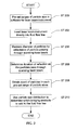
- FIG. 3 shows a flow chart in accordance with one or more embodiments disclosed herein.
- FIGS. 4-7 show data review screens for measuring particle size distribution in accordance with one or more embodiments disclosed herein.
- embodiments disclosed herein provide a method and apparatus for measuring particle size distribution in a drilling fluid flow line. More specifically, embodiments disclosed herein relate to laser-based reflectance measurements for evaluation of particle size distribution for bridging of formation pores and fractures in an oil reservoir.
- FIG. 1 shows a laser beam instrument in accordance with one or more embodiments disclosed herein.
- the laser beam instrument includes a laser beam ( 102 ), optics ( 104 ), and a probe window ( 106 ).
- the laser beam instrument is a probe tube ( 100 ) that includes a laser beam ( 102 ).
- the laser beam ( 102 ) is generated from a solid-state laser light source ( 101 ) that provides a continuous beam of monochromatic light that is launched down the laser probe ( 100 ).
- the light source may be any light source capable of generating a laser beam.
- An intricate set of lenses i.e., optics ( 104 )) focuses the laser light to a small spot on the surface of the probe window ( 106 ). This focal spot is carefully calibrated to be positioned at the interface between the probe window and the actual process. Tightly controlling the position of the focal spot is necessary for a sensitive and repeatable measurement.
- a precision motor (not shown) (e.g., a pneumatic or an electric motor) is used to rotate the precision optics ( 104 ) in a circular motion at a constant speed.
- the rotating optics act to split the laser beam ( 102 ) into a circle rotating with an alternating speed between 2 and 4 m/s.
- the speed is carefully monitored and controlled throughout the measurement to ensure maximum precision in the data.
- standard probes operate to provide a fixed scan speed between 1 and 4 m/s.
- the scan speed is 2 m/s for finer particles and 4 m/s for coarse particles.
- the focused beam ( 110 ) scans a circular path at the interface between the probe window ( 106 ) and the fluid flow line ( 108 ). As the scanning focused beam ( 110 ) sweeps across the face of the probe window ( 106 ), individual particles or particle structures backscatter the laser light back to the probe tube ( 100 ). Particles and droplets closest to the probe window ( 106 ) are located in the scanning focused spot and backscatter distinct pulses of reflected light. That is, the backscattered light is detected by the probe tube ( 100 ) as a pulse measured from one edge of the particle to the opposite edge of the particle.
- the pulses of backscattered light are detected by the probe ( 100 ) and translated into chord lengths based on the a calculation of the scan speed (velocity) multiplied by the pulse width (time).
- a chord length is simply defined as the straight-line distance from one edge of a particle or particle structure to another edge (i.e., the diameter of a particle).
- FIG. 2 shows a chord length calculation in accordance with one or more embodiments disclosed herein. Specifically, FIG. 2 shows a high velocity scanning laser beam that scans across the diameter of each particle that reflects off the laser beam. The duration of reflection measured is a chord.
- chord length distribution shows the number of individual chords measured per second (y-axis) as a function of the chord length dimension (x-axis).
- the chord length distribution as a “fingerprint” of the particle system, provides the ability to detect and monitor changes in particle dimension and particle count in real time.
- the laser beam instrument determines the particle size distribution (PSD) of a fluid flow line with an accuracy of 1000-2000 ⁇ m.
- the laser beam instrument disclosed herein makes no assumption of particle shape. This allows the fundamental measurement to be used to directly track changes in the particle system without unnecessary complex mathematical assumptions that could introduce significant errors to the measurement.
- the laser beam instrument may be a Lasentec® FBRM® (Focused Beam Reflection Measurement) instrument, commercially available from METTLER TOLEDO (Columbus, Ohio).
- the probe window ( 106 ) is a sapphire window.
- the laser beam instrument (probe) described in FIG. 1 is used to measure PSD of particles in a fluid line that provides a wellbore fluid to bridge/plug fractures and pores in a reservoir. More specifically, the bridging material (also known as lost circulation material (LCM)) is added to the fluid flow line and the PSD of the bridging material is calculated using the laser beam instrument described above. Bridging material is a substance added to cement slurries or drilling mud to prevent the loss of cement or mud to the formation and may be fibrous, flaky, or granular material.
- LCM lost circulation material
- Bridging materials may include, but are not limited to, Fordadol Z2, G-Seal® (provided by M-I LLC (Houston, Tex.)), Microdol 40/200, Calcium Carbonate M, and/or any combination thereof.
- an ideal blend of bridging materials i.e., an ideal packing theory combines 4-6 bridging products, such as those described above.
- the laser beam instrument in embodiments disclosed herein is able to provide a continuous measurement of particle sizes and changes in PSD while adding various sized products to a fluid flow line.
- the size of the particles that are added does not affect the instrument's ability to detect changes in PSD.
- the laser beam instrument is set up (in a training phase) in software before being inserted into the fluid flow line for purposes of obtaining PSD measurements.
- Table 1 shows an overview of products, planned concentrations, and particle size ranges used in the software setup for the laser beam instrument. The ranges are chosen as typical ranges for characterization of each added bridging material such that the laser beam instrument may identify changes in population of each bridging product as they are added to the fluid flow line.
- the particle sizes are chosen to cover both pore bridging and bridging of induced or natural fractures while drilling depleted zones in the reservoir.
- the PSD measurements obtained by the laser beam instrument are count based rather than based on normalized values.
- the count based interpretation allows for each channel in the system to be independent of changes in other regions of the distribution.
- the measured particles may be grouped into the different ranges shown in Table 1 in the laser beam instrument software and report form. This enables offshore personnel to maintain the concentration of the different bridging materials in the rig inventory according to actual changes in particle size distribution.
- FIG. 3 shows a flow chart in accordance with one or more embodiments of the present disclosure.
- software values for the concentrations and particle size groups for various LCM/bridging materials are pre-set in the laser beam instrument (ST 200 ).
- the scanning speed is set both in hardware and software, and determines what size range may be detected by the instrument. For example, a scanning speed of 4 m/s is applicable for sizes 2-2048 ⁇ mm.
- the laser beam instrument may be toggled between a scanning speed of 2 and 4 m/s. The scanning speed is set by the rotational speed of the optics module, which is pneumatically driven.
- the probe tube including the laser beam instrument is inserted directly into the fluid flow line (ST 202 ).
- the probe window of the laser beam instrument is placed directly into the particle system (the fluid flow line).
- the probe tube may also be inserted into a return line of drilling fluid, where the return line includes drilling fluid traveling upward to the surface; thus, embodiments disclosed herein are not limited to a laser beam instrument that is inserted only into a flow line.
- the probe tube is inserted into a turbulent well-mixed fluid flow line at an angle between 30 and 60 degrees.
- the laser beam instrument is inserted at a 45 degree angle into the fluid flow line.
- a measurement of the diameter or chord length of particles is obtained using the reflectance of particles passing through scanning laser beam (ST 204 ).
- the duration of the reflection of the particles is determined (ST 206 ).
- the method of measurement is based on the duration of reflection as the particles pass through the high velocity scanning laser beam.
- the duration of reflection measured provides the chord length of each particle, as discussed above.
- the measurements depend on the shape of the particles and the orientation of the particles as the measurement is actually registered.
- the high number of measurements typically 50000-200000 particles/second
- a measure of the diameter of the particles over a specific time interval e.g., 30 seconds
- This calculation is subsequently performed to obtain the count of particles in each particle size group range (ST 208 ).
- the particle size count for each particle size group is used to determine what blend of bridging materials to add to the fluid flow line to bridge pores and fractures in the reservoir (ST 210 ).
- the particle size count is also used to determine the required minimum particle concentration necessary to identify changes in PSD due to additions of particles.
- the probe instrument measures changes in particle sizes for each individual addition of particles into the drilling fluid, regardless of the size of the particles that are added to the flow line.
- PSD is used to determine the blend of particles of bridging materials that is needed to plug pores and fractures in a reservoir.
- the PSD measurements may also be used to determine the effectiveness and verify the bridging effect of a blend of bridging products that is added to the fluid flow line.
- the PSD measurements may also be used to determine how much material for preventing fractures in the reservoir is needed.
- the preventative materials can also be added to the flow line in a manner similar to the bridging materials that are used to plug existing fractures and pores.
- PSD measurements may also be used to replace measurement of NTUs (Nephelometric Turbidity Units).
- Turbidity refers to how ‘cloudy’ a fluid is, and an NTU is a measurement unit that measures the lack of clarity of water, which could also be affected by the particle size distribution.
- the laser beam instrument includes a fine mode and a coarse mode.
- the coarse mode allows the instrument to interpret particles with very rough edges or even agglomerates as one particle.
- the course mode is a signal filter applied to the data before turning the data into chord lengths. This is useful for the characterization of large particles in the presence of many small particles.
- Fine mode is more sensitive than coarse mode, and is used to identify small particles. In one or more embodiments, fine mode is the default mode.
- FIGS. 4-7 show data review screens of the laser beam instrument in accordance with embodiments of the present disclosure during various examples of circulating fluid and adding a one or more bridging material(s) to the fluid. Each figure is described in more detail below.
- FIG. 4 shows a data review screen for the addition of Fordadol Z2 bridging product in accordance with one or more embodiments disclosed herein. More specifically, FIG. 4 shows the data review screen while circulating and conditioning the fluid before product addition for bridging fractures and pores is added.
- the left window shows the PSD of the fluid while circulating.
- the crosshair in the right side window shows a graph of particle size distribution a short while after the addition of 10 g/l Fordadol Z2 with a D50>1000 ⁇ m.
- the laser beam instrument measures the change in particle counts between 632 and 2000 ⁇ m, which is the pre-set range in the software to identify the Fordadol Z2 product.
- the curve in the right window demonstrates that the particle count shows a steady increase after the addition of the product completes. This increase may be because some particle agglomerates are larger than the instruments maximum readable size of 2000 ⁇ m and the counts increase over time as these large agglomerates disperse.
- FIG. 5 shows changes in the PSD measured by the laser beam instrument due to the addition of G-Seal® bridging product.
- the curve in the right hand window shows a sharp increase ( 500 ) in particle counts immediately after addition of 35 g/l G-Seal®.
- the amount of G-Seal® added to the fluid flow line may be any amount, and that 35 g/l is merely an example.
- the decreased particle count after the initial peak is due to attrition effect as the particles are reduced in size mechanically.
- the change may also be caused by aggregates that disperse over the first few circulations in the fluid flow loop before the fluid reaches a homogenous condition.
- a first curve ( 502 ) in the left hand size window describes PSD before any addition of particles from bridging materials.
- a second curve ( 504 ) shows PSD after addition of Fordadol Z2 and is close to the first curve ( 502 ) except for the increase of particles in the 1000 ⁇ m range.
- a third curve ( 506 ) describes the expected shift to the right in the size area between 200 and 700 ⁇ m following the addition of G-Seal®.
- FIG. 6 shows changes in the PSD measured by the laser beam instrument due to the addition of Microdol 40/200 bridging product.
- the specified size range used to identify Microdol 40/200 that is pre-set into the laser beam instrument using software is 47-252 ⁇ m.
- the addition of Microdol 40/200 shows a similar trend as with the addition of G-Seal® described in FIG. 5 .
- the smaller fraction of G-Seal® falls in line with the coarser fraction of the Microdol 40/200, and thus, is registered by the laser beam instrument in the same manner as the addition of G-Seal®.
- the higher number of counts of particles between 47 and 252 ⁇ m before the addition of Microdol 40/200 indicates that the treated field fluid that was used as a basis to obtain this data review output graph included a certain concentration of particles within this range.
- the crosshair in the right window is set at the peak immediately after addition of Microdol 40/200.
- FIG. 7 shows changes in the PSD measured by the laser beam instrument due to the addition of Calcium Carbonate M bridging product. There is no evidenced in FIG. 6 of an increase in counts between 2-50 ⁇ m at the cross hair in the right window. This may be due to the relatively high concentration of fine particles present in the fluid before any additions and the finer fraction of the coarser additives.
- the laser beam instrument and software associated with the laser beam instrument are set up to focus primarily on the coarser particles rather than finer particles, which accounts for the graphs shown in FIG. 7 .
- Embodiments of the disclosure provide a method and apparatus for determining particle size distribution of various materials in a fluid flow line using reflectance of particles in the fluid flow line.
- the apparatus laser beam instrument
- the apparatus is inserted directly into the flow line, without having to sample the flow line, resulting in a more accurate determine of the PSD in the flow line.
- the method of the present disclosure provides an actual count of PSD, rather than normalized values of PSD.
Landscapes
- Life Sciences & Earth Sciences (AREA)
- Mining & Mineral Resources (AREA)
- Engineering & Computer Science (AREA)
- Physics & Mathematics (AREA)
- Chemical & Material Sciences (AREA)
- Geology (AREA)
- Dispersion Chemistry (AREA)
- Biochemistry (AREA)
- Geochemistry & Mineralogy (AREA)
- Fluid Mechanics (AREA)
- Environmental & Geological Engineering (AREA)
- Health & Medical Sciences (AREA)
- Analytical Chemistry (AREA)
- General Life Sciences & Earth Sciences (AREA)
- General Health & Medical Sciences (AREA)
- General Physics & Mathematics (AREA)
- Immunology (AREA)
- Pathology (AREA)
- Investigating Or Analysing Materials By Optical Means (AREA)
- Length Measuring Devices By Optical Means (AREA)
Priority Applications (1)
| Application Number | Priority Date | Filing Date | Title |
|---|---|---|---|
| US13/123,541 US8427640B2 (en) | 2008-10-23 | 2009-10-21 | Method and apparatus for measuring particle size distribution in drilling fluid |
Applications Claiming Priority (3)
| Application Number | Priority Date | Filing Date | Title |
|---|---|---|---|
| US10780108P | 2008-10-23 | 2008-10-23 | |
| US13/123,541 US8427640B2 (en) | 2008-10-23 | 2009-10-21 | Method and apparatus for measuring particle size distribution in drilling fluid |
| PCT/US2009/061471 WO2010048276A2 (fr) | 2008-10-23 | 2009-10-21 | Procédé et appareil pour mesurer une distribution de taille de particule dans un fluide de forage |
Related Parent Applications (1)
| Application Number | Title | Priority Date | Filing Date |
|---|---|---|---|
| PCT/US2009/061471 A-371-Of-International WO2010048276A2 (fr) | 2008-10-23 | 2009-10-21 | Procédé et appareil pour mesurer une distribution de taille de particule dans un fluide de forage |
Related Child Applications (1)
| Application Number | Title | Priority Date | Filing Date |
|---|---|---|---|
| US13/868,039 Continuation US9007580B2 (en) | 2008-10-23 | 2013-04-22 | Method and apparatus for measuring particle size distribution in drilling fluid |
Publications (2)
| Publication Number | Publication Date |
|---|---|
| US20110192595A1 US20110192595A1 (en) | 2011-08-11 |
| US8427640B2 true US8427640B2 (en) | 2013-04-23 |
Family
ID=42119956
Family Applications (1)
| Application Number | Title | Priority Date | Filing Date |
|---|---|---|---|
| US13/123,541 Active 2030-03-04 US8427640B2 (en) | 2008-10-23 | 2009-10-21 | Method and apparatus for measuring particle size distribution in drilling fluid |
Country Status (8)
| Country | Link |
|---|---|
| US (1) | US8427640B2 (fr) |
| EP (1) | EP2909604B1 (fr) |
| AR (1) | AR073966A1 (fr) |
| BR (1) | BRPI0920623A2 (fr) |
| CA (1) | CA2740587C (fr) |
| EA (1) | EA021737B1 (fr) |
| MX (1) | MX2011004164A (fr) |
| WO (1) | WO2010048276A2 (fr) |
Cited By (4)
| Publication number | Priority date | Publication date | Assignee | Title |
|---|---|---|---|---|
| WO2015156893A1 (fr) * | 2014-04-11 | 2015-10-15 | Particle Size Engineering, LLC | Contrôle de la dimension de particule dans un fluide de forage |
| US20150293006A1 (en) * | 2008-10-23 | 2015-10-15 | M-I L.L.C. | Method and apparatus for measuring particle size distribution in drilling fluid |
| US9664036B2 (en) | 2013-10-09 | 2017-05-30 | Halliburton Energy Services, Inc. | Systems and methods for measuring downhole fluid characteristics in drilling fluids |
| US10151677B2 (en) | 2014-07-08 | 2018-12-11 | Halliburton Energy Services, Inc. | Real-time optical flow imaging to determine particle size distribution |
Families Citing this family (8)
| Publication number | Priority date | Publication date | Assignee | Title |
|---|---|---|---|---|
| WO2012099234A1 (fr) | 2011-01-20 | 2012-07-26 | オリンパス株式会社 | Procédé de photoanalyse et dispositif associé faisant appel à la détection de la lumière émise par une particule luminescente individuelle |
| EP2746748B1 (fr) | 2011-08-15 | 2017-12-06 | Olympus Corporation | Dispositif d'analyse photométrique par détection de particules électroluminescentes individuelles, procédé et programme d'ordinateur afférents |
| CN103765196B (zh) | 2011-08-26 | 2016-03-02 | 奥林巴斯株式会社 | 利用单个发光粒子检测的光分析装置及光分析方法 |
| WO2013052796A1 (fr) | 2011-10-07 | 2013-04-11 | Saudi Arabian Oil Company | Mode de classification de matériaux de pontage dimensionnés pour une excellente configuration de fluide de forage |
| US11077521B2 (en) * | 2014-10-30 | 2021-08-03 | Schlumberger Technology Corporation | Creating radial slots in a subterranean formation |
| WO2017098597A1 (fr) | 2015-12-09 | 2017-06-15 | オリンパス株式会社 | Procédé d'analyse optique et dispositif d'analyse optique utilisant une détection de particule électroluminescente unique |
| CN111195454A (zh) * | 2018-11-16 | 2020-05-26 | 研能科技股份有限公司 | 净化气体装置 |
| CN112781495B (zh) * | 2020-12-31 | 2022-07-12 | 合肥工业大学 | 一种基于悬浮激光结构的三维接触触发式测量探头 |
Citations (6)
| Publication number | Priority date | Publication date | Assignee | Title |
|---|---|---|---|---|
| US4728190A (en) | 1985-10-15 | 1988-03-01 | Particle Measuring Systems, Inc. | Device and method for optically detecting particles in a fluid |
| US4917496A (en) | 1988-07-11 | 1990-04-17 | Pacific Scientific Company | Particle size measuring instrument with direct scattered light detection |
| US5043591A (en) | 1987-11-10 | 1991-08-27 | The Secretary Of State For Defence In Her Britannic Majesty's Government Of The United Kingdom Of Great Britain And Northern Ireland | Portable particle analysers having plural detectors |
| KR20020021808A (ko) | 2000-06-12 | 2002-03-22 | 이에츠구 히사시 | 면역분석법 및 면역분석장치 |
| KR20030083321A (ko) | 2002-04-20 | 2003-10-30 | 엘지산전 주식회사 | 부하개폐 커넥터 |
| US20060274309A1 (en) | 2005-06-06 | 2006-12-07 | Particle Measuring Systems Inc | Particle counter with improved image sensor array |
Family Cites Families (5)
| Publication number | Priority date | Publication date | Assignee | Title |
|---|---|---|---|---|
| US4871251A (en) | 1987-04-27 | 1989-10-03 | Preikschat F K | Apparatus and method for particle analysis |
| US5815264A (en) * | 1994-09-21 | 1998-09-29 | Laser Sensor Technology, Inc | System for acquiring an image of a multi-phase fluid by measuring backscattered light |
| GB2335269A (en) * | 1998-03-10 | 1999-09-15 | Messtechnik Schwartz Gmbh | Measuring particles in a flowing fluid |
| DE60029878T2 (de) | 1999-05-04 | 2007-03-15 | Mettler-Toledo Autochem, Inc. | Verfahren und Vorrichtung zur Bestimmung von Teilchen unter Benutzung der Reflexion eines mehrfachabtastenden Strahls |
| US7050166B2 (en) * | 2001-11-02 | 2006-05-23 | Baker Hughes Incorporated | Calcium carbonate imaging technique |
-
2009
- 2009-10-21 CA CA2740587A patent/CA2740587C/fr not_active Expired - Fee Related
- 2009-10-21 EA EA201170599A patent/EA021737B1/ru not_active IP Right Cessation
- 2009-10-21 US US13/123,541 patent/US8427640B2/en active Active
- 2009-10-21 EP EP09822619.4A patent/EP2909604B1/fr active Active
- 2009-10-21 WO PCT/US2009/061471 patent/WO2010048276A2/fr not_active Ceased
- 2009-10-21 BR BRPI0920623A patent/BRPI0920623A2/pt not_active IP Right Cessation
- 2009-10-21 MX MX2011004164A patent/MX2011004164A/es active IP Right Grant
- 2009-10-23 AR ARP090104098A patent/AR073966A1/es active IP Right Grant
Patent Citations (6)
| Publication number | Priority date | Publication date | Assignee | Title |
|---|---|---|---|---|
| US4728190A (en) | 1985-10-15 | 1988-03-01 | Particle Measuring Systems, Inc. | Device and method for optically detecting particles in a fluid |
| US5043591A (en) | 1987-11-10 | 1991-08-27 | The Secretary Of State For Defence In Her Britannic Majesty's Government Of The United Kingdom Of Great Britain And Northern Ireland | Portable particle analysers having plural detectors |
| US4917496A (en) | 1988-07-11 | 1990-04-17 | Pacific Scientific Company | Particle size measuring instrument with direct scattered light detection |
| KR20020021808A (ko) | 2000-06-12 | 2002-03-22 | 이에츠구 히사시 | 면역분석법 및 면역분석장치 |
| KR20030083321A (ko) | 2002-04-20 | 2003-10-30 | 엘지산전 주식회사 | 부하개폐 커넥터 |
| US20060274309A1 (en) | 2005-06-06 | 2006-12-07 | Particle Measuring Systems Inc | Particle counter with improved image sensor array |
Non-Patent Citations (3)
| Title |
|---|
| International Search Report from PCT/US2009/061471 dated May 28, 2010 (2 pages). |
| Official Action issued in corresponding Eurasian Application No. 201170599 with English Language Communication reporting the same; Dated Feb. 11, 2013 (4 pages). |
| Written Opinion from PCT/US2009/061471 dated May 28, 2010 (4 pages). |
Cited By (5)
| Publication number | Priority date | Publication date | Assignee | Title |
|---|---|---|---|---|
| US20150293006A1 (en) * | 2008-10-23 | 2015-10-15 | M-I L.L.C. | Method and apparatus for measuring particle size distribution in drilling fluid |
| US10228315B2 (en) * | 2008-10-23 | 2019-03-12 | M-I L.L.C. | Method and apparatus for measuring particle size distribution in drilling fluid |
| US9664036B2 (en) | 2013-10-09 | 2017-05-30 | Halliburton Energy Services, Inc. | Systems and methods for measuring downhole fluid characteristics in drilling fluids |
| WO2015156893A1 (fr) * | 2014-04-11 | 2015-10-15 | Particle Size Engineering, LLC | Contrôle de la dimension de particule dans un fluide de forage |
| US10151677B2 (en) | 2014-07-08 | 2018-12-11 | Halliburton Energy Services, Inc. | Real-time optical flow imaging to determine particle size distribution |
Also Published As
| Publication number | Publication date |
|---|---|
| EP2909604B1 (fr) | 2019-06-26 |
| EA021737B1 (ru) | 2015-08-31 |
| BRPI0920623A2 (pt) | 2015-12-22 |
| WO2010048276A2 (fr) | 2010-04-29 |
| US20110192595A1 (en) | 2011-08-11 |
| EP2909604A4 (fr) | 2016-08-03 |
| CA2740587A1 (fr) | 2010-04-29 |
| AR073966A1 (es) | 2010-12-15 |
| WO2010048276A3 (fr) | 2010-07-29 |
| CA2740587C (fr) | 2014-08-19 |
| EA201170599A1 (ru) | 2011-10-31 |
| EP2909604A2 (fr) | 2015-08-26 |
| MX2011004164A (es) | 2011-06-24 |
Similar Documents
| Publication | Publication Date | Title |
|---|---|---|
| US8427640B2 (en) | Method and apparatus for measuring particle size distribution in drilling fluid | |
| US10228315B2 (en) | Method and apparatus for measuring particle size distribution in drilling fluid | |
| Maaß et al. | Experimental comparison of measurement techniques for drop size distributions in liquid/liquid dispersions | |
| US11739479B2 (en) | Yankee dryer profiler and control | |
| CA2923008C (fr) | Systemes et procedes pour mesurer des caracteristiques de fluide de fond dans des fluides de forage | |
| WO1997034139A1 (fr) | Procede et systeme pour mesurer la geometrie des particules | |
| Kail et al. | Advanced geometrical modeling of focused beam reflectance measurements (FBRM) | |
| Abbas et al. | Investigation of on-line optical particle characterization in reaction and cooling crystallization systems. Current state of the art | |
| US8149401B2 (en) | System and method for distinguishing particles in a transient fluid | |
| Less et al. | Light beam reflectance measurement of droplets diameter distribution in crude oil emulsions | |
| US20180134973A1 (en) | Method for On-line Imaging of Mesophase Particles | |
| Oort et al. | Automated drilling fluid analysis using advanced particle size analyzers | |
| WO2010055280A1 (fr) | Détermination de la distribution de taille de particules d'une suspension | |
| Akbari et al. | An effective image based surface roughness estimation approach using neural network | |
| Michihata et al. | Three-dimensional measurement of structures with smooth-steep-surfaces using autofluorescence confocal signal | |
| US12498320B2 (en) | Method for monitoring the precipitation of inorganic salts in aqueous systems | |
| CN105758824A (zh) | 基于布里渊散射的海洋石油污染检测方法 | |
| US6559950B1 (en) | Method for monitoring a characteristic of a mixture comprising particles suspended in a liquid | |
| CN223289439U (zh) | 测量设备 | |
| Rheims et al. | Working Principle and Experimental Results for a Differential Phase‐Doppler Technique | |
| Tran et al. | Estimation of mud and sand fractions and total concentration from coupled optical-acoustic sensors | |
| Kirkiewicz et al. | Comparative studies of water turbidity on the grounds of a nephelometric method and diffraction effects | |
| Castagner et al. | A double Gaussian beam method for the determination of particle size, direction and velocity | |
| van Oort et al. | IADC/SPE-178877-MS | |
| Pérez-Moret et al. | Design and Construction of the automated scatterometer for particle sizing |
Legal Events
| Date | Code | Title | Description |
|---|---|---|---|
| AS | Assignment |
Owner name: M-I SWACO NORGE AS, NORWAY Free format text: ASSIGNMENT OF ASSIGNORS INTEREST;ASSIGNOR:RONAES, EGIL;REEL/FRAME:026105/0734 Effective date: 20091111 Owner name: M-I L.L.C., TEXAS Free format text: ASSIGNMENT OF ASSIGNORS INTEREST;ASSIGNOR:FREEMAN, MICHAEL A.;REEL/FRAME:026105/0711 Effective date: 20091221 Owner name: SCHLUMBERGER NORGE AS, NORWAY Free format text: ASSIGNMENT OF ASSIGNORS INTEREST;ASSIGNOR:M-I SWACO NORGE AS;REEL/FRAME:026105/0683 Effective date: 20110228 |
|
| STCF | Information on status: patent grant |
Free format text: PATENTED CASE |
|
| RR | Request for reexamination filed |
Effective date: 20150423 |
|
| FPAY | Fee payment |
Year of fee payment: 4 |
|
| FPB1 | Reexamination decision cancelled all claims |
Kind code of ref document: C1 Free format text: REEXAMINATION CERTIFICATE Filing date: 20150423 Effective date: 20180302 |
|
| MAFP | Maintenance fee payment |
Free format text: PAYMENT OF MAINTENANCE FEE, 8TH YEAR, LARGE ENTITY (ORIGINAL EVENT CODE: M1552); ENTITY STATUS OF PATENT OWNER: LARGE ENTITY Year of fee payment: 8 |
|
| MAFP | Maintenance fee payment |
Free format text: PAYMENT OF MAINTENANCE FEE, 12TH YEAR, LARGE ENTITY (ORIGINAL EVENT CODE: M1553); ENTITY STATUS OF PATENT OWNER: LARGE ENTITY Year of fee payment: 12 |