US8435453B2 - Device for performing chemical and/or physical reactions between a solid material and a gas - Google Patents
Device for performing chemical and/or physical reactions between a solid material and a gas Download PDFInfo
- Publication number
- US8435453B2 US8435453B2 US13/003,130 US200813003130A US8435453B2 US 8435453 B2 US8435453 B2 US 8435453B2 US 200813003130 A US200813003130 A US 200813003130A US 8435453 B2 US8435453 B2 US 8435453B2
- Authority
- US
- United States
- Prior art keywords
- gas
- duct
- solids
- stage
- solid material
- Prior art date
- Legal status (The legal status is an assumption and is not a legal conclusion. Google has not performed a legal analysis and makes no representation as to the accuracy of the status listed.)
- Expired - Fee Related, expires
Links
- 239000011343 solid material Substances 0.000 title claims abstract description 27
- 238000006243 chemical reaction Methods 0.000 title claims abstract description 9
- 239000000126 substance Substances 0.000 title claims abstract description 9
- 239000007787 solid Substances 0.000 claims abstract description 57
- 239000000725 suspension Substances 0.000 claims abstract description 38
- 238000007599 discharging Methods 0.000 claims abstract description 10
- 238000001354 calcination Methods 0.000 claims abstract description 7
- 238000001816 cooling Methods 0.000 claims abstract description 7
- 239000000463 material Substances 0.000 claims abstract description 7
- 230000001174 ascending effect Effects 0.000 claims description 7
- 239000004568 cement Substances 0.000 description 2
- 238000010276 construction Methods 0.000 description 2
- 239000002994 raw material Substances 0.000 description 2
- 238000000926 separation method Methods 0.000 description 2
- 239000000428 dust Substances 0.000 description 1
- 238000007654 immersion Methods 0.000 description 1
- 239000002245 particle Substances 0.000 description 1
- JTJMJGYZQZDUJJ-UHFFFAOYSA-N phencyclidine Chemical class C1CCCCN1C1(C=2C=CC=CC=2)CCCCC1 JTJMJGYZQZDUJJ-UHFFFAOYSA-N 0.000 description 1
Images




Classifications
-
- F—MECHANICAL ENGINEERING; LIGHTING; HEATING; WEAPONS; BLASTING
- F27—FURNACES; KILNS; OVENS; RETORTS
- F27B—FURNACES, KILNS, OVENS OR RETORTS IN GENERAL; OPEN SINTERING OR LIKE APPARATUS
- F27B7/00—Rotary-drum furnaces, i.e. horizontal or slightly inclined
- F27B7/20—Details, accessories or equipment specially adapted for rotary-drum furnaces
- F27B7/2016—Arrangements of preheating devices for the charge
- F27B7/2025—Arrangements of preheating devices for the charge consisting of a single string of cyclones
- F27B7/2033—Arrangements of preheating devices for the charge consisting of a single string of cyclones with means for precalcining the raw material
-
- B—PERFORMING OPERATIONS; TRANSPORTING
- B01—PHYSICAL OR CHEMICAL PROCESSES OR APPARATUS IN GENERAL
- B01D—SEPARATION
- B01D45/00—Separating dispersed particles from gases or vapours by gravity, inertia, or centrifugal forces
- B01D45/12—Separating dispersed particles from gases or vapours by gravity, inertia, or centrifugal forces by centrifugal forces
- B01D45/16—Separating dispersed particles from gases or vapours by gravity, inertia, or centrifugal forces by centrifugal forces generated by the winding course of the gas stream, the centrifugal forces being generated solely or partly by mechanical means, e.g. fixed swirl vanes
-
- B—PERFORMING OPERATIONS; TRANSPORTING
- B01—PHYSICAL OR CHEMICAL PROCESSES OR APPARATUS IN GENERAL
- B01J—CHEMICAL OR PHYSICAL PROCESSES, e.g. CATALYSIS OR COLLOID CHEMISTRY; THEIR RELEVANT APPARATUS
- B01J19/00—Chemical, physical or physico-chemical processes in general; Their relevant apparatus
- B01J19/24—Stationary reactors without moving elements inside
- B01J19/2415—Tubular reactors
- B01J19/243—Tubular reactors spirally, concentrically or zigzag wound
-
- B—PERFORMING OPERATIONS; TRANSPORTING
- B01—PHYSICAL OR CHEMICAL PROCESSES OR APPARATUS IN GENERAL
- B01J—CHEMICAL OR PHYSICAL PROCESSES, e.g. CATALYSIS OR COLLOID CHEMISTRY; THEIR RELEVANT APPARATUS
- B01J8/00—Chemical or physical processes in general, conducted in the presence of fluids and solid particles; Apparatus for such processes
- B01J8/005—Separating solid material from the gas/liquid stream
-
- B—PERFORMING OPERATIONS; TRANSPORTING
- B01—PHYSICAL OR CHEMICAL PROCESSES OR APPARATUS IN GENERAL
- B01J—CHEMICAL OR PHYSICAL PROCESSES, e.g. CATALYSIS OR COLLOID CHEMISTRY; THEIR RELEVANT APPARATUS
- B01J8/00—Chemical or physical processes in general, conducted in the presence of fluids and solid particles; Apparatus for such processes
- B01J8/08—Chemical or physical processes in general, conducted in the presence of fluids and solid particles; Apparatus for such processes with moving particles
-
- C—CHEMISTRY; METALLURGY
- C04—CEMENTS; CONCRETE; ARTIFICIAL STONE; CERAMICS; REFRACTORIES
- C04B—LIME, MAGNESIA; SLAG; CEMENTS; COMPOSITIONS THEREOF, e.g. MORTARS, CONCRETE OR LIKE BUILDING MATERIALS; ARTIFICIAL STONE; CERAMICS; REFRACTORIES; TREATMENT OF NATURAL STONE
- C04B7/00—Hydraulic cements
- C04B7/36—Manufacture of hydraulic cements in general
- C04B7/43—Heat treatment, e.g. precalcining, burning, melting; Cooling
-
- F—MECHANICAL ENGINEERING; LIGHTING; HEATING; WEAPONS; BLASTING
- F28—HEAT EXCHANGE IN GENERAL
- F28C—HEAT-EXCHANGE APPARATUS, NOT PROVIDED FOR IN ANOTHER SUBCLASS, IN WHICH THE HEAT-EXCHANGE MEDIA COME INTO DIRECT CONTACT WITHOUT CHEMICAL INTERACTION
- F28C3/00—Other direct-contact heat-exchange apparatus
- F28C3/10—Other direct-contact heat-exchange apparatus one heat-exchange medium at least being a fluent solid, e.g. a particulate material
- F28C3/12—Other direct-contact heat-exchange apparatus one heat-exchange medium at least being a fluent solid, e.g. a particulate material the heat-exchange medium being a particulate material and a gas, vapour, or liquid
-
- F—MECHANICAL ENGINEERING; LIGHTING; HEATING; WEAPONS; BLASTING
- F28—HEAT EXCHANGE IN GENERAL
- F28F—DETAILS OF HEAT-EXCHANGE AND HEAT-TRANSFER APPARATUS, OF GENERAL APPLICATION
- F28F13/00—Arrangements for modifying heat-transfer, e.g. increasing, decreasing
- F28F13/06—Arrangements for modifying heat-transfer, e.g. increasing, decreasing by affecting the pattern of flow of the heat-exchange media
Definitions
- the invention relates to a device for performing chemical and/or physical reactions between a solid material and a gas, especially for preheating, cooling and/or calcining fine-grained materials, having several stages arranged one above the other.
- systems comprising parallel-flow heat exchangers and cyclone separators are known from practice for the preheating, cooling and/or calcining of fine-grained materials.
- Such devices generally have several stages arranged one above the other, the gas stream being conducted from the bottom to the top through all of the stages, while the solid material is delivered to the individual stages in the opposite direction.
- a further problem resides in the fact that, in the case of structural forms of different sizes, the centrifugal forces change, with the same inlet rates, thereby giving rise to other separating conditions.
- U.S. Pat. No. 4,318,692 therefore proposed a multi-stage preheater for cement raw material, the individual stages of which each comprise a riser and an adjoining helical and/or spiral duct.
- the helical and/or spiral duct has a rectangular cross-section and is connected to one side of a quadrangular hopper in which the solid material and the gas are finally separated by centrifugal and inertial forces.
- the object of the invention is to reduce the device for performing chemical and/or physical reactions between a solid material and a gas with regard to the overall height.
- the device according to the invention for performing chemical and/or physical reactions between a solid material and a gas, especially for preheating, cooling and/or calcining fine-grained materials has at least three stages arranged one above the other, each stage comprising the following components:
- junction of the solids duct and the gas-solids suspension duct of the third or a higher stage is provided below the highest point of the gas-solids suspension duct arranged two stages lower.
- the gas-solids suspension duct comprises an ascending and a descending duct portion which may be formed by a riser and a descending helical and/or spiral duct.
- a redirecting head which connects the riser to the helical and/or spiral duct may also be provided. Owing to the ascending and descending duct portion, on the one hand sufficient contact time between the solid material and the gas is ensured and, on the other hand, the overall height can be further reduced.
- a helical and/or spiral duct in the context of the invention is to be understood as being a duct which is in a helical and/or spiral shape at least in portions.
- the turning of the helical and/or spiral duct may, in particular, also extend over only a relatively small angular range of, for example, 90°.
- the helical and/or spiral ducts of consecutive stages have alternating left-handed and right-handed orientations.
- the changing direction of turn gives an extremely compact construction of the device, which permits a further reduction in the overall height.
- a reduction in the overall height of up to 25% can be achieved in comparison with a conventional five-stage cyclone-suspension type heat exchanger.
- the solids duct and the gas duct are connected to the end of the helical and/or spiral duct, there being provided, for example, at the end of the helical and/or spiral duct, a separating chamber to which the solids duct for discharging the solids stream and the gas duct for discharging the gas stream are connected.
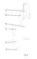
- FIG. 1 is a side view of one stage of the device
- FIG. 2 is a side view according to FIG. 1 rotated through 90°
- FIG. 3 is a plan view of the stage according to FIG. 1 .
- FIG. 4 is a side view of the device having three stages arranged one above the other and
- FIG. 5 is a plan view of the device according to FIG. 4 .
- FIGS. 1 to 3 show in detail one stage of a device for performing chemical and/or physical reactions between a solid material and a gas, especially for preheating, cooling and/or calcining fine-grained materials.
- It basically comprises a gas-solids suspension duct 1 , means for separating the delivered solid material from the delivered gas, which, in the embodiment shown, are formed by a separating chamber 2 , a solids duct 3 for discharging the separated solid material and a gas duct 4 for discharging the separated gas.
- the gas-solids suspension is delivered to the separating chamber 2 by way of the gas-solids suspension duct 1 .
- the gas-solids suspension duct 1 has an ascending duct portion in the form of a riser 1 a and a descending duct portion in the form of a helical and/or spiral duct 1 b . Also provided is a redirecting head 1 c which connects the riser 1 a to the helical and/or spiral duct 1 b . Viewed in the vertical direction, at least the beginning of the helical and/or spiral duct 1 b is positioned higher up than its mouth end at the separating chamber 2 . In the helical and/or spiral duct 1 b , the gas-solids suspension is separated into a solids stream and a gas stream owing to the centrifugal forces.
- the radius and/or the ascending gradient and/or the cross-sectional shape and/or the cross-sectional size of the helical and/or spiral duct 1 b it is possible for the radius and/or the ascending gradient and/or the cross-sectional shape and/or the cross-sectional size of the helical and/or spiral duct 1 b to change in the direction of flow of the gas-solids suspension.
- the radius, ascending gradient, cross-sectional shape and/or cross-sectional size can change in the direction of flow discontinuously and/or, at least in one portion, also continuously.
- a reduction in the radius brings about an increase in the centrifugal force
- an increase in the radius corresponds to a reduction in the centrifugal force.
- the helical and/or spiral duct 1 b joins the separating chamber 2 tangentially at an angle ⁇ to the horizontal of at least 30°.
- the separating chamber 2 has a cylindrical portion 2 a which is adjoined below by a portion 2 b which tapers in the shape of a funnel.
- the solids duct 3 is connected to the portion 2 b of the separating chamber that tapers in the shape of a funnel, while the cylindrical portion 2 a merges into the gas duct 4 .
- the gas duct 4 and the cylindrical portion 2 a of the separating chamber have the same diameter. It could therefore also be said that the separating chamber is formed by the lower portion of the gas duct 4 .
- the gas duct 4 could project into the separating chamber 2 in the manner of an immersion tube or to be constructed with a larger diameter than the separating chamber.
- the solid material is conducted in an arc into the portion 2 b of the separating chamber 2 that tapers in the shape of a funnel and then passes into the solids duct 3 (see FIGS. 1 and 3 ).
- the gas 6 is drawn off upwardly into the gas duct 4 with a swirling motion (see FIG. 1 ).
- the flow, directed obliquely downwards, in the separating chamber 2 also prevents the inlet gas stream from being overlaid by the swirling flow formed in the separating chamber in the region of the mouth of the helical and/or spiral duct 1 b.
- the means for separating the delivered solid material from the delivered gas can, however, also be constructed entirely or in part in the gas-solids suspension duct 1 .
- the helical and/or spiral duct 1 b extends over an angular range of approximately 180°.
- the angular range can, however, also be selected to be markedly larger or smaller. It is also possible for the radius and/or the ascending gradient and/or the cross-sectional shape and/or the cross-sectional size of the helical and/or spiral duct 1 b to change in the direction of flow of the gas-solids suspension.
- the device according to the invention for performing chemical and/or physical reactions between a solid material and a gas comprises several stages arranged one above the other, as described above with reference to FIGS. 1 to 3 .
- the gas duct of one stage merges into the gas-solids suspension duct of the next-higher stage and the solids duct of one stage joins the gas-solids suspension duct of the next-lower stage.
- a device having three stages I, II, III which is, for example, a three-stage preheater for cement raw material, is described hereinafter with reference to FIGS. 4 and 5 .
- a solid material to be treated is delivered to the uppermost stage III by way of a solids duct 3 ′′′ and is drawn off as a treated solid material 5 , for example, a preheated solid material, from the lowermost stage I. While the solid material is thus guided through the three stages from the top to the bottom, the gas flows through the arrangement in the opposite direction.
- the gas 6 to be delivered to the lowermost stage is, for example, the hot exhaust gas of a kiln or a calciner.
- the gas 6 ′′ drawn off from the third stage by way of the gas duct 4 ′′ is, for example, for the purpose of dust removal, delivered to a filter, or to a highly efficient separator arranged downstream.
- the treated solid material 5 passes, for example, into a calciner or a kiln for further processing.
- the three stages can be arranged very compactly and in such a manner that they are intertwined. It is also provided that the helical and/or spiral ducts 1 b , 1 ′ b , 1 ′′ b of at least two consecutive stages are oriented alternately with a left-handed and right-handed turn (see FIG. 5 ).
- the gas-solids suspension ducts especially the helical and/or spiral ducts of two stages following each other in the direction of gas flow, can be arranged in a meandering shape.
- An especially low structural form can be achieved if, in the case of at least three stages arranged one above the other, the junction of the solids duct and the gas-solids suspension duct of the third or a higher stage is provided below the highest point of the gas-solids suspension duct arranged two stages lower.
- the solids duct 3 ′′′ which is connected to the riser 1 ′′ a of the third stage III, is provided below the highest point of the gas-solids suspension duct of the lowermost stage I.
Landscapes
- Chemical & Material Sciences (AREA)
- Organic Chemistry (AREA)
- Chemical Kinetics & Catalysis (AREA)
- Engineering & Computer Science (AREA)
- Ceramic Engineering (AREA)
- Physics & Mathematics (AREA)
- General Engineering & Computer Science (AREA)
- Thermal Sciences (AREA)
- Mechanical Engineering (AREA)
- Materials Engineering (AREA)
- Structural Engineering (AREA)
- Devices And Processes Conducted In The Presence Of Fluids And Solid Particles (AREA)
- Furnace Details (AREA)
Applications Claiming Priority (1)
| Application Number | Priority Date | Filing Date | Title |
|---|---|---|---|
| PCT/EP2008/058101 WO2009155973A1 (de) | 2008-06-25 | 2008-06-25 | Vorrichtung zur durchführung chemischer und/oder physikalischer reaktionen zwischen einem feststoff und einem gas |
Publications (2)
| Publication Number | Publication Date |
|---|---|
| US20110165031A1 US20110165031A1 (en) | 2011-07-07 |
| US8435453B2 true US8435453B2 (en) | 2013-05-07 |
Family
ID=40419034
Family Applications (1)
| Application Number | Title | Priority Date | Filing Date |
|---|---|---|---|
| US13/003,130 Expired - Fee Related US8435453B2 (en) | 2008-06-25 | 2008-06-25 | Device for performing chemical and/or physical reactions between a solid material and a gas |
Country Status (5)
| Country | Link |
|---|---|
| US (1) | US8435453B2 (de) |
| EP (1) | EP2288861B1 (de) |
| CN (1) | CN102171527A (de) |
| AT (1) | ATE536522T1 (de) |
| WO (1) | WO2009155973A1 (de) |
Cited By (1)
| Publication number | Priority date | Publication date | Assignee | Title |
|---|---|---|---|---|
| US20200275608A1 (en) * | 2012-04-16 | 2020-09-03 | Billy Goat Industries, Inc. | Debris-collecting apparatus and method of collecting debris |
Families Citing this family (2)
| Publication number | Priority date | Publication date | Assignee | Title |
|---|---|---|---|---|
| CN113509894B (zh) * | 2021-07-22 | 2023-04-14 | 中冶赛迪工程技术股份有限公司 | 移动床气固径向反应器 |
| CN115999256B (zh) * | 2023-01-09 | 2026-02-03 | 北京航空航天大学 | 一种用于高温空气除尘的两级u型过滤管道系统 |
Citations (15)
| Publication number | Priority date | Publication date | Assignee | Title |
|---|---|---|---|---|
| US2866272A (en) | 1954-09-28 | 1958-12-30 | Smidth & Co As F L | Cyclone heat exchange apparatus |
| US3207484A (en) * | 1963-06-20 | 1965-09-21 | Ind Process Engineers Inc | Fluid mixing device |
| US3904353A (en) * | 1973-05-14 | 1975-09-09 | Holderbank Management | Method and apparatus for the heat treatment of a material in powder form |
| US3975148A (en) * | 1974-02-19 | 1976-08-17 | Onoda Cement Company, Ltd. | Apparatus for calcining cement |
| US4022568A (en) * | 1974-08-12 | 1977-05-10 | F. L. Smidth & Co. | Method and apparatus for heat treating pulverous raw materials |
| US4039277A (en) * | 1974-11-07 | 1977-08-02 | Ishikawajima-Harima Jukogyo Kabushiki Kaisha | Apparatus for calcining powder materials |
| US4071310A (en) * | 1975-10-28 | 1978-01-31 | Fives-Cail Babcock | Installation for the manufacture of cement |
| US4119396A (en) * | 1976-02-10 | 1978-10-10 | Kockner-Humboldt-Deutz Aktiengesellschaft | Method and apparatus for the thermal treatment of moist, granular materials |
| US4191526A (en) * | 1977-04-07 | 1980-03-04 | Polysius Ag | Suspension gas preheater |
| US4248641A (en) * | 1977-06-10 | 1981-02-03 | Klockner-Humboldt-Deutz Ag | Method and apparatus for the production of cement clinkers from moist agglomerated raw material |
| US4318692A (en) | 1981-01-02 | 1982-03-09 | Allis-Chalmers Corporation | Helical duct gas/meal separator |
| US4715811A (en) * | 1985-07-01 | 1987-12-29 | Fuller Company | Process and apparatus for manufacturing low sulfur cement clinker |
| US5217368A (en) * | 1991-02-08 | 1993-06-08 | Fcb | Process and apparatus for the thermal treatment of minerals in powdery form |
| US5269637A (en) * | 1991-05-24 | 1993-12-14 | Serrana S/A De Mineracao | Single-loop dust separation cyclone |
| US6574885B1 (en) * | 1998-12-28 | 2003-06-10 | Tetrapat | Cyclone heat exchanger |
-
2008
- 2008-06-25 AT AT08774294T patent/ATE536522T1/de active
- 2008-06-25 EP EP08774294A patent/EP2288861B1/de not_active Not-in-force
- 2008-06-25 CN CN200880130927XA patent/CN102171527A/zh active Pending
- 2008-06-25 US US13/003,130 patent/US8435453B2/en not_active Expired - Fee Related
- 2008-06-25 WO PCT/EP2008/058101 patent/WO2009155973A1/de not_active Ceased
Patent Citations (15)
| Publication number | Priority date | Publication date | Assignee | Title |
|---|---|---|---|---|
| US2866272A (en) | 1954-09-28 | 1958-12-30 | Smidth & Co As F L | Cyclone heat exchange apparatus |
| US3207484A (en) * | 1963-06-20 | 1965-09-21 | Ind Process Engineers Inc | Fluid mixing device |
| US3904353A (en) * | 1973-05-14 | 1975-09-09 | Holderbank Management | Method and apparatus for the heat treatment of a material in powder form |
| US3975148A (en) * | 1974-02-19 | 1976-08-17 | Onoda Cement Company, Ltd. | Apparatus for calcining cement |
| US4022568A (en) * | 1974-08-12 | 1977-05-10 | F. L. Smidth & Co. | Method and apparatus for heat treating pulverous raw materials |
| US4039277A (en) * | 1974-11-07 | 1977-08-02 | Ishikawajima-Harima Jukogyo Kabushiki Kaisha | Apparatus for calcining powder materials |
| US4071310A (en) * | 1975-10-28 | 1978-01-31 | Fives-Cail Babcock | Installation for the manufacture of cement |
| US4119396A (en) * | 1976-02-10 | 1978-10-10 | Kockner-Humboldt-Deutz Aktiengesellschaft | Method and apparatus for the thermal treatment of moist, granular materials |
| US4191526A (en) * | 1977-04-07 | 1980-03-04 | Polysius Ag | Suspension gas preheater |
| US4248641A (en) * | 1977-06-10 | 1981-02-03 | Klockner-Humboldt-Deutz Ag | Method and apparatus for the production of cement clinkers from moist agglomerated raw material |
| US4318692A (en) | 1981-01-02 | 1982-03-09 | Allis-Chalmers Corporation | Helical duct gas/meal separator |
| US4715811A (en) * | 1985-07-01 | 1987-12-29 | Fuller Company | Process and apparatus for manufacturing low sulfur cement clinker |
| US5217368A (en) * | 1991-02-08 | 1993-06-08 | Fcb | Process and apparatus for the thermal treatment of minerals in powdery form |
| US5269637A (en) * | 1991-05-24 | 1993-12-14 | Serrana S/A De Mineracao | Single-loop dust separation cyclone |
| US6574885B1 (en) * | 1998-12-28 | 2003-06-10 | Tetrapat | Cyclone heat exchanger |
Cited By (2)
| Publication number | Priority date | Publication date | Assignee | Title |
|---|---|---|---|---|
| US20200275608A1 (en) * | 2012-04-16 | 2020-09-03 | Billy Goat Industries, Inc. | Debris-collecting apparatus and method of collecting debris |
| US11690331B2 (en) * | 2012-04-16 | 2023-07-04 | Briggs & Stratton, Llc | Debris-collecting apparatus and method of collecting debris |
Also Published As
| Publication number | Publication date |
|---|---|
| ATE536522T1 (de) | 2011-12-15 |
| EP2288861B1 (de) | 2011-12-07 |
| US20110165031A1 (en) | 2011-07-07 |
| WO2009155973A1 (de) | 2009-12-30 |
| CN102171527A (zh) | 2011-08-31 |
| EP2288861A1 (de) | 2011-03-02 |
Similar Documents
| Publication | Publication Date | Title |
|---|---|---|
| EP2480335B1 (de) | Zyklon zur abscheidung klebriger partikel aus gasströmen | |
| CN104066698A (zh) | 氯旁路装置 | |
| WO2010001097A1 (en) | Cyclone separator with two gas outlets and separation method | |
| JPH01242161A (ja) | サイクロン | |
| WO2012036845A1 (en) | Cyclone separator | |
| US20110165031A1 (en) | Device for performing chemical and/or physical reactions between a solid material and a gas | |
| US20050155916A1 (en) | Cylindrical telescopic structure cyclone apparatus | |
| US8439670B2 (en) | Device for separating a solid material and a gas and a plant for cement manufacture | |
| EP0165668B1 (de) | Wärmeaustauscher | |
| EP3359899B1 (de) | Mehrstufiger suspensionsvorwärmer für zementkalzinieranlage | |
| US4326845A (en) | Suspension preheater for cement calcining plant | |
| US4342576A (en) | Particle separator | |
| US20110097679A1 (en) | Device for performing chemical and/or physical reactions between a solid material and a gas | |
| JPH0376962B2 (de) | ||
| RU2463539C2 (ru) | Устройство для проведения химических и/или физических реакций между твердым веществом и газом | |
| CN116465206B (zh) | 一种导气内置式旋风预热器 | |
| EP2571622B1 (de) | Zyklonabscheider mit zwei gasauslässen und abscheideverfahren | |
| RU61597U1 (ru) | Устройство для очистки газов от пыли | |
| GB2079190A (en) | Particle Separating Apparatus | |
| MXPA05001515A (es) | Proceso y dispositivo para la separacion de un catalizador utilizando un ciclon en un proceso fcc. | |
| JPH0431520Y2 (de) | ||
| RU68367U1 (ru) | Циклон | |
| JP2002239419A (ja) | 低圧損型サイクロン | |
| CN117722860A (zh) | 一种进行两次预热的嵌套式旋风预热器 | |
| WO2003090899A1 (en) | A method and an equipment for separating solids from a gas flow and the use of the same |
Legal Events
| Date | Code | Title | Description |
|---|---|---|---|
| AS | Assignment |
Owner name: POLYSIUS AG, GERMANY Free format text: ASSIGNMENT OF ASSIGNORS INTEREST;ASSIGNORS:GEORG, VERENA;KUPPER, DETLEV;GARCIA, LUIS LAGAR;AND OTHERS;SIGNING DATES FROM 20101214 TO 20110126;REEL/FRAME:025820/0543 |
|
| AS | Assignment |
Owner name: THYSSENKRUPP POLYSIUS AKTIENGESELLSCHAFT, GERMANY Free format text: CHANGE OF NAME;ASSIGNOR:POLYSIUS AG;REEL/FRAME:026691/0957 Effective date: 20110622 |
|
| STCF | Information on status: patent grant |
Free format text: PATENTED CASE |
|
| FEPP | Fee payment procedure |
Free format text: PAYOR NUMBER ASSIGNED (ORIGINAL EVENT CODE: ASPN); ENTITY STATUS OF PATENT OWNER: LARGE ENTITY |
|
| FPAY | Fee payment |
Year of fee payment: 4 |
|
| FEPP | Fee payment procedure |
Free format text: MAINTENANCE FEE REMINDER MAILED (ORIGINAL EVENT CODE: REM.); ENTITY STATUS OF PATENT OWNER: LARGE ENTITY |
|
| LAPS | Lapse for failure to pay maintenance fees |
Free format text: PATENT EXPIRED FOR FAILURE TO PAY MAINTENANCE FEES (ORIGINAL EVENT CODE: EXP.); ENTITY STATUS OF PATENT OWNER: LARGE ENTITY |
|
| STCH | Information on status: patent discontinuation |
Free format text: PATENT EXPIRED DUE TO NONPAYMENT OF MAINTENANCE FEES UNDER 37 CFR 1.362 |
|
| FP | Lapsed due to failure to pay maintenance fee |
Effective date: 20210507 |