US8439590B2 - Knuckle protector for a vehicle - Google Patents
Knuckle protector for a vehicle Download PDFInfo
- Publication number
- US8439590B2 US8439590B2 US12/999,477 US99947709A US8439590B2 US 8439590 B2 US8439590 B2 US 8439590B2 US 99947709 A US99947709 A US 99947709A US 8439590 B2 US8439590 B2 US 8439590B2
- Authority
- US
- United States
- Prior art keywords
- flange
- screen
- annular
- side wing
- housing
- Prior art date
- Legal status (The legal status is an assumption and is not a legal conclusion. Google has not performed a legal analysis and makes no representation as to the accuracy of the status listed.)
- Expired - Fee Related, expires
Links
Images


Classifications
-
- B—PERFORMING OPERATIONS; TRANSPORTING
- B62—LAND VEHICLES FOR TRAVELLING OTHERWISE THAN ON RAILS
- B62D—MOTOR VEHICLES; TRAILERS
- B62D7/00—Steering linkage; Stub axles or their mountings
- B62D7/16—Arrangement of linkage connections
- B62D7/166—Arrangement of linkage connections substantially perpendicular, e.g. between tie-rod and steering knuckle
-
- B—PERFORMING OPERATIONS; TRANSPORTING
- B60—VEHICLES IN GENERAL
- B60G—VEHICLE SUSPENSION ARRANGEMENTS
- B60G7/00—Pivoted suspension arms; Accessories thereof
- B60G7/005—Ball joints
-
- F—MECHANICAL ENGINEERING; LIGHTING; HEATING; WEAPONS; BLASTING
- F16—ENGINEERING ELEMENTS AND UNITS; GENERAL MEASURES FOR PRODUCING AND MAINTAINING EFFECTIVE FUNCTIONING OF MACHINES OR INSTALLATIONS; THERMAL INSULATION IN GENERAL
- F16C—SHAFTS; FLEXIBLE SHAFTS; ELEMENTS OR CRANKSHAFT MECHANISMS; ROTARY BODIES OTHER THAN GEARING ELEMENTS; BEARINGS
- F16C11/00—Pivots; Pivotal connections
- F16C11/04—Pivotal connections
- F16C11/06—Ball-joints; Other joints having more than one degree of angular freedom, i.e. universal joints
-
- F—MECHANICAL ENGINEERING; LIGHTING; HEATING; WEAPONS; BLASTING
- F16—ENGINEERING ELEMENTS AND UNITS; GENERAL MEASURES FOR PRODUCING AND MAINTAINING EFFECTIVE FUNCTIONING OF MACHINES OR INSTALLATIONS; THERMAL INSULATION IN GENERAL
- F16C—SHAFTS; FLEXIBLE SHAFTS; ELEMENTS OR CRANKSHAFT MECHANISMS; ROTARY BODIES OTHER THAN GEARING ELEMENTS; BEARINGS
- F16C17/00—Sliding-contact bearings for exclusively rotary movement
- F16C17/12—Sliding-contact bearings for exclusively rotary movement characterised by features not related to the direction of the load
- F16C17/24—Sliding-contact bearings for exclusively rotary movement characterised by features not related to the direction of the load with devices affected by abnormal or undesired positions, e.g. for preventing overheating, for safety
- F16C17/243—Sliding-contact bearings for exclusively rotary movement characterised by features not related to the direction of the load with devices affected by abnormal or undesired positions, e.g. for preventing overheating, for safety related to temperature and heat, e.g. for preventing overheating
-
- B—PERFORMING OPERATIONS; TRANSPORTING
- B60—VEHICLES IN GENERAL
- B60G—VEHICLE SUSPENSION ARRANGEMENTS
- B60G2204/00—Indexing codes related to suspensions per se or to auxiliary parts
- B60G2204/40—Auxiliary suspension parts; Adjustment of suspensions
- B60G2204/416—Ball or spherical joints
-
- B—PERFORMING OPERATIONS; TRANSPORTING
- B60—VEHICLES IN GENERAL
- B60G—VEHICLE SUSPENSION ARRANGEMENTS
- B60G2204/00—Indexing codes related to suspensions per se or to auxiliary parts
- B60G2204/40—Auxiliary suspension parts; Adjustment of suspensions
- B60G2204/43—Fittings, brackets or knuckles
- B60G2204/4308—Protecting guards, e.g. for rigid axle damage protection
-
- F—MECHANICAL ENGINEERING; LIGHTING; HEATING; WEAPONS; BLASTING
- F16—ENGINEERING ELEMENTS AND UNITS; GENERAL MEASURES FOR PRODUCING AND MAINTAINING EFFECTIVE FUNCTIONING OF MACHINES OR INSTALLATIONS; THERMAL INSULATION IN GENERAL
- F16C—SHAFTS; FLEXIBLE SHAFTS; ELEMENTS OR CRANKSHAFT MECHANISMS; ROTARY BODIES OTHER THAN GEARING ELEMENTS; BEARINGS
- F16C11/00—Pivots; Pivotal connections
- F16C11/04—Pivotal connections
- F16C11/06—Ball-joints; Other joints having more than one degree of angular freedom, i.e. universal joints
- F16C11/0619—Ball-joints; Other joints having more than one degree of angular freedom, i.e. universal joints the female part comprising a blind socket receiving the male part
-
- F—MECHANICAL ENGINEERING; LIGHTING; HEATING; WEAPONS; BLASTING
- F16—ENGINEERING ELEMENTS AND UNITS; GENERAL MEASURES FOR PRODUCING AND MAINTAINING EFFECTIVE FUNCTIONING OF MACHINES OR INSTALLATIONS; THERMAL INSULATION IN GENERAL
- F16C—SHAFTS; FLEXIBLE SHAFTS; ELEMENTS OR CRANKSHAFT MECHANISMS; ROTARY BODIES OTHER THAN GEARING ELEMENTS; BEARINGS
- F16C11/00—Pivots; Pivotal connections
- F16C11/04—Pivotal connections
- F16C11/06—Ball-joints; Other joints having more than one degree of angular freedom, i.e. universal joints
- F16C11/0666—Sealing means between the socket and the inner member shaft
- F16C11/0671—Sealing means between the socket and the inner member shaft allowing operative relative movement of joint parts due to flexing of the sealing means
-
- F—MECHANICAL ENGINEERING; LIGHTING; HEATING; WEAPONS; BLASTING
- F16—ENGINEERING ELEMENTS AND UNITS; GENERAL MEASURES FOR PRODUCING AND MAINTAINING EFFECTIVE FUNCTIONING OF MACHINES OR INSTALLATIONS; THERMAL INSULATION IN GENERAL
- F16C—SHAFTS; FLEXIBLE SHAFTS; ELEMENTS OR CRANKSHAFT MECHANISMS; ROTARY BODIES OTHER THAN GEARING ELEMENTS; BEARINGS
- F16C2202/00—Solid materials defined by their properties
- F16C2202/20—Thermal properties
- F16C2202/24—Insulating
-
- F—MECHANICAL ENGINEERING; LIGHTING; HEATING; WEAPONS; BLASTING
- F16—ENGINEERING ELEMENTS AND UNITS; GENERAL MEASURES FOR PRODUCING AND MAINTAINING EFFECTIVE FUNCTIONING OF MACHINES OR INSTALLATIONS; THERMAL INSULATION IN GENERAL
- F16C—SHAFTS; FLEXIBLE SHAFTS; ELEMENTS OR CRANKSHAFT MECHANISMS; ROTARY BODIES OTHER THAN GEARING ELEMENTS; BEARINGS
- F16C2326/00—Articles relating to transporting
- F16C2326/01—Parts of vehicles in general
- F16C2326/05—Vehicle suspensions, e.g. bearings, pivots or connecting rods used therein
-
- F—MECHANICAL ENGINEERING; LIGHTING; HEATING; WEAPONS; BLASTING
- F16—ENGINEERING ELEMENTS AND UNITS; GENERAL MEASURES FOR PRODUCING AND MAINTAINING EFFECTIVE FUNCTIONING OF MACHINES OR INSTALLATIONS; THERMAL INSULATION IN GENERAL
- F16C—SHAFTS; FLEXIBLE SHAFTS; ELEMENTS OR CRANKSHAFT MECHANISMS; ROTARY BODIES OTHER THAN GEARING ELEMENTS; BEARINGS
- F16C2326/00—Articles relating to transporting
- F16C2326/20—Land vehicles
- F16C2326/24—Steering systems, e.g. steering rods or columns
-
- Y—GENERAL TAGGING OF NEW TECHNOLOGICAL DEVELOPMENTS; GENERAL TAGGING OF CROSS-SECTIONAL TECHNOLOGIES SPANNING OVER SEVERAL SECTIONS OF THE IPC; TECHNICAL SUBJECTS COVERED BY FORMER USPC CROSS-REFERENCE ART COLLECTIONS [XRACs] AND DIGESTS
- Y10—TECHNICAL SUBJECTS COVERED BY FORMER USPC
- Y10T—TECHNICAL SUBJECTS COVERED BY FORMER US CLASSIFICATION
- Y10T403/00—Joints and connections
- Y10T403/16—Joints and connections with adjunctive protector, broken parts retainer, repair, assembly or disassembly feature
-
- Y—GENERAL TAGGING OF NEW TECHNOLOGICAL DEVELOPMENTS; GENERAL TAGGING OF CROSS-SECTIONAL TECHNOLOGIES SPANNING OVER SEVERAL SECTIONS OF THE IPC; TECHNICAL SUBJECTS COVERED BY FORMER USPC CROSS-REFERENCE ART COLLECTIONS [XRACs] AND DIGESTS
- Y10—TECHNICAL SUBJECTS COVERED BY FORMER USPC
- Y10T—TECHNICAL SUBJECTS COVERED BY FORMER US CLASSIFICATION
- Y10T403/00—Joints and connections
- Y10T403/32—Articulated members
- Y10T403/32606—Pivoted
- Y10T403/32819—Pivoted including tension or take-up means
- Y10T403/32852—External of bearing assembly, e.g., antirattler, etc.
Definitions
- the present invention relates to a device for protecting a knuckle joint, which is for instance an element of the front steering or the suspension of a vehicle.
- this type of knuckle joint also called knuckle
- knuckle is mounted on the ball joint pin of the suspension arm or on the ball joint pin of the steering rack.
- the knuckle is very close to the brake disc, which is a significant heat source.
- the brake disc of a loaded utility vehicle can reach a temperature of up to 700° C.
- a knuckle comprises mainly a knuckle articulation which is crimped to create the articulation and a boot in elastomeric rubber enveloping the assembly to protect it against dust.
- Document EP0890500 discloses a protection device for the knuckle joint of a vehicle comprising an annular flange mounted on the knuckle, a heat screen which extends in height perpendicularly to the flange and in width along the annular periphery of the flange.
- Flange and screen are formed in one piece in a deep draw stamping operation starting from sheet metal. This operation is most often performed in several passes, in other words in several stamping operations. The process is not only long but also costly in energy, handling and stamping tooling.
- the present invention provides a device for protecting the knuckle joint of a vehicle that is simple to fabricate and less costly, and is resistant to deformation in order not to damage the nearby steering and suspension elements.
- the present invention provides a knuckle joint protection device for instance for the steering or the suspension of a vehicle, comprising an annular flange mounted on the knuckle joint and a heat screen, this screen extends in height perpendicularly to the flange and in width along the annular periphery of the flange, characterized in that screen and flange are formed in one piece from sheet metal bent in a connecting zone between screen and flange; furthermore part of the surface of the screen is in the form of a side wing which extends along the annular periphery of the flange, this side wing is separated from the flange by a notch in the form of a slot.
- This arrangement contributes to obtaining a protection device that can be fabricated mainly by bending sheet metal, because the length of the connecting zone between screen and flange is not excessive. It is clear that this notch in the form of a slot, separating the side wing from the flange, leads to the creation of a large protection surface with a sufficiently small connecting zone in order to form the device by bending. Contrary to a deep draw stamping operation, bending is a simple, inexpensive and fast operation, which can be performed by a conventional machine tool.
- the protection device according to the invention can have the following features:
- the present invention provides a protection device for knuckle joint for instance of the steering and/or suspension of a vehicle, including an annular flange mounting to the knuckle joint and a heat screen, this screen extends in height perpendicularly to the flange and in width along the annular periphery of the flange, characterized in that the screen and the flange are formed in one piece of sheet metal which is bent in a connecting zone between the screen and the flange, the screen has moreover a surface part in the form of a side wing which extends along the periphery of the annular flange, this side wing is separated from the flange in the sheet metal by a notch in the form of a slot.
- FIG. 1 illustrates the protection device according to a first implementation mode of the invention
- FIGS. 2 a and 2 b show the protection device in installed position on a knuckle joint
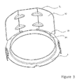
- FIG. 3 shows the protection device according to a second implementation mode of the invention.
- FIG. 1 shows a protection device 1 for knuckle joint (illustrated in FIGS. 2 a and 2 b ) of a vehicle comprising mainly an annular flange 2 mounted on the knuckle joint, here in the form of a disc with a central opening, and a heat screen 3 for protecting against the heat emitted by the brake discs.
- Screen 3 extends in height perpendicularly to flange 2 and in width along the annular periphery of the flange.
- the central opening of the mounting flange 2 has a circular shape mating with the also circular external contour of the knuckle, over which it passes for installation of the protection device.
- the inside diameter of the opening measures 44 m and the external diameter of the annular flange 2 measures 55 mm.
- the heat screen has a rectangular shape and its dimensions are sufficient to protect the whole surface of the rubber boot of the knuckle, deflecting the heat effects and creating an air zone.
- the size of the screen can be 57 mm wide and 28 mm high.
- the screen extends along the outside periphery of the annular mounting flange 2 . It is connected to flange 2 along a bent connection or a connection zone 4 constituting a central part 5 of the longitudinal edge of screen 3 .
- This connection zone 4 defines the central body 5 of screen 3 which extends radially starting from the connection zone 4 .
- the heat screen 3 comprises furthermore one or two side wings 6 arranged on both sides of central body 5 .
- the side wings extend along the annular periphery of flange 2 . According to the invention, they are separated from flange 2 by a notch in the form of a slot 12 .
- the side wings 6 are detached from flange 2 , in other words they are only connected to flange 2 through the intermediary of central body 5 and a space is left free between the wings and the outside periphery of flange 2 .
- this notch 12 in the form of a slot leads to the creation of a sufficiently wide screen to protect the knuckle and a sufficiently short connecting zone 4 to bend the screen relative to flange 2 in a perpendicular arrangement.
- the side wings 6 extend beyond the central body 5 over a distance at least equivalent to approximately half the width of said central body. For instance, central body 5 and side wings 6 measure 19 mm by 28 mm.
- Mounting flange 2 and screen 3 are made in a single piece, in other words by cutting one piece of plate or sheet metal, with thickness for instance between 0.5 and 2 mm.
- the protection device 1 is then formed by simple bending of screen 3 relative to the mounting flange 2 so that they are perpendicular to each other.
- the side wings are bent down to follow, with the central body, the outside periphery of the mounting flange 2 .
- the protection device 1 illustrated in FIG. 1 in formed configuration, was made by cutting and bending operations.
- reinforcement ribs 7 are obtained by a deformation operation of the junction between the central body 5 and the side wings 6 .
- this operation is performed when the screen is in formed configuration.
- the ribs 7 extend along the width of screen 3 forming protuberances in the inside part of the formed screen and ribs on the outside. This arrangement reinforces the rigidity of the screen running along the periphery of flange 2 .
- protuberances are formed in the shape of blocking tabs or tenons 8 extending radially starting from the outside periphery of the mounting disc 2 .
- Tenons 8 are subsequently bent to be perpendicular to flange 2 in the same manner as screen 3 .
- the blocking tabs are positioned at the periphery of the mounting flange 2 so as to face the extremities of side wings 6 when the protection device 1 is formed.
- at least one pair of blocking tabs is provided facing the extremity of each side wing 6 .
- the tabs of one pair are offset on the outside periphery of disc 2 to define a radial space between them corresponding to the thickness of the side wing. Consequently, arranged in this way, tabs 8 pinch the lower edge of the wing, blocking the wing along the annular periphery of the flange.
- the mounting disc 2 comprises a centering collar 9 , for insertion of the knuckle in the central opening, and at least two tabs 10 for mounting the protection device on the knuckle.
- the centering collar 9 is of cylindrical shape and extends in coaxial manner starting from the inside edge of the annular flange 2 in the bending direction of screen 3 .
- the height of the centering collar 9 is approximately ten times smaller than its diameter, or approximately equal to 5 mm.
- the centering collar 9 is made in a simple one step stamping operation in an inexpensive machine. It is clear that the centering collar 9 must be made in such manner during the cutting operation of the sheet metal that the central opening of the annular flange corresponds to the knuckle joint.
- the mounting tabs 10 are protuberances in the form of teeth extending axially starting from the outside periphery of the mounting flange 2 in the opposite direction of centering collar 9 .
- the two mounting tabs 10 are arranged diametrically opposite to each other on the outside periphery of flange 2 with central body 5 of screen 3 situated in a median plane to the two tabs 10 .
- the mounting tabs 10 are made during the cutting step of the sheet metal and form radial protuberances which are then bent in axial direction in the opposite direction of the bending of screen 3 .
- Each mounting tab has a rectangular shape with one side tangential to the outside periphery of flange 2 .
- a “U” shape is cut in each tab 10 forming a flexible tongue 11 attached to the extremity of tab 10 .
- the tongue 11 is then deformed to achieve an “S” shaped section. Consequently, the flexible tongue 11 is shorter than the mounting tab 10 and rounded towards the inside of flange 2 for passage and insertion in the washer of the knuckle as illustrated in FIGS. 2 a and 2 b.
- FIGS. 2 a and 2 b show a knuckle joint 21 of a vehicle equipped with the protection device 1 according to the invention.
- the installed heat screen 3 performs the function of heat barrier around boot 22 .
- the knuckle joint is in this way protected against heating of the brake disc.
- the knuckle joint is inserted in the central opening of the mounting flange 2 , the centering collar 9 guiding the spindle of the knuckle.
- centering collar 9 is married to the periphery of the knuckle 21 and the flexible tongues 11 click or snap in washer 23 of the knuckle joint.
- the mounting flange 2 is then blocked in axial direction by means of mounting tabs 10 which click in washer 23 .
- Any other type of mounting of the protection device on the knuckle can be provided.
- the protection device can be mounted by clamping between washer and knuckle.
- the protection device 1 is mounted on knuckle 21 with screen 3 protecting boot 22 .
- FIG. 3 shows an alternative mounting of the extremities of the side wings 32 .
- the protection device according to the invention 31 has side wings 32 provided with blocking tabs or tenons 33 formed in the wing sheet metal cooperating with corresponding holes or openings 34 formed in the outside periphery of the mounting flange 2 .
- the blocking tabs 33 extend sideways in direction of the mounting flange 2 . They are made during the cutting step in the same manner as the corresponding openings 34 .
Landscapes
- Engineering & Computer Science (AREA)
- Mechanical Engineering (AREA)
- General Engineering & Computer Science (AREA)
- Chemical & Material Sciences (AREA)
- Combustion & Propulsion (AREA)
- Transportation (AREA)
- Pivots And Pivotal Connections (AREA)
- Steering-Linkage Mechanisms And Four-Wheel Steering (AREA)
- Snaps, Bayonet Connections, Set Pins, And Snap Rings (AREA)
- Butt Welding And Welding Of Specific Article (AREA)
- Vehicle Interior And Exterior Ornaments, Soundproofing, And Insulation (AREA)
- Automatic Cycles, And Cycles In General (AREA)
- Sealing Devices (AREA)
- Joints Allowing Movement (AREA)
Applications Claiming Priority (4)
| Application Number | Priority Date | Filing Date | Title |
|---|---|---|---|
| FR0855861A FR2935452B1 (fr) | 2008-09-02 | 2008-09-02 | Protecteur de rotule de vehicule. |
| FR08/55861 | 2008-09-02 | ||
| FR0855861 | 2008-09-02 | ||
| PCT/EP2009/006172 WO2010025866A1 (fr) | 2008-09-02 | 2009-08-26 | Protecteur de rotule de vehicule |
Publications (2)
| Publication Number | Publication Date |
|---|---|
| US20110262211A1 US20110262211A1 (en) | 2011-10-27 |
| US8439590B2 true US8439590B2 (en) | 2013-05-14 |
Family
ID=40626548
Family Applications (1)
| Application Number | Title | Priority Date | Filing Date |
|---|---|---|---|
| US12/999,477 Expired - Fee Related US8439590B2 (en) | 2008-09-02 | 2009-08-26 | Knuckle protector for a vehicle |
Country Status (7)
| Country | Link |
|---|---|
| US (1) | US8439590B2 (fr) |
| EP (1) | EP2331833B1 (fr) |
| CN (1) | CN102138013B (fr) |
| AT (1) | ATE542056T1 (fr) |
| BR (1) | BRPI0917650A2 (fr) |
| FR (1) | FR2935452B1 (fr) |
| WO (1) | WO2010025866A1 (fr) |
Cited By (1)
| Publication number | Priority date | Publication date | Assignee | Title |
|---|---|---|---|---|
| US20230264533A1 (en) * | 2022-02-24 | 2023-08-24 | Benteler Automobiltechnik Gmbh | Chassis link |
Families Citing this family (6)
| Publication number | Priority date | Publication date | Assignee | Title |
|---|---|---|---|---|
| FR3005928B1 (fr) * | 2013-05-21 | 2015-06-05 | Peugeot Citroen Automobiles Sa | Ensemble pour la protection thermique de rotules d'un vehicule automobile |
| JP6301141B2 (ja) * | 2014-01-30 | 2018-03-28 | 本田技研工業株式会社 | 不整地走行車両の懸架構造 |
| FR3029582B1 (fr) * | 2014-12-03 | 2016-12-30 | Peugeot Citroen Automobiles Sa | Dispositif de protection d’une rotule de suspension comprenant une gouttiere contre les ruissellements |
| JP6382753B2 (ja) * | 2015-03-11 | 2018-08-29 | 株式会社クボタ | 作業車 |
| FR3035927A1 (fr) * | 2015-05-05 | 2016-11-11 | Peugeot Citroen Automobiles Sa | Dispositifs et procede de protection thermique de rotule |
| DE102015217219A1 (de) * | 2015-09-09 | 2017-03-09 | Zf Friedrichshafen Ag | Schutzkappe, Kugelgelenk mit einer solchen Schutzkappe und Zweipunktlenker mit einem derartigen Kugelgelenk |
Citations (15)
| Publication number | Priority date | Publication date | Assignee | Title |
|---|---|---|---|---|
| US2243222A (en) * | 1940-09-30 | 1941-05-27 | James F Barnes | Cornice |
| US2483621A (en) * | 1948-03-16 | 1949-10-04 | Kermit E Nash | Tie rod safety attachment |
| US2657945A (en) * | 1950-01-30 | 1953-11-03 | Fred R Britt | Safety covering for tie-rod ends |
| US2888148A (en) * | 1955-11-21 | 1959-05-26 | Waldorf Paper Prod Co | Shelf extenders |
| US3326503A (en) * | 1965-09-03 | 1967-06-20 | Falk Corp | Speed reducer mounting assembly |
| US3742552A (en) * | 1972-05-01 | 1973-07-03 | Miller R & Co Inc | Indexing furniture glide |
| JPS62172180A (ja) * | 1986-01-24 | 1987-07-29 | 株式会社日立製作所 | 金属ウランの溶解装置 |
| US5203522A (en) * | 1991-07-03 | 1993-04-20 | United Technologies Corporation | Resealable protective boot |
| EP0570736A1 (fr) | 1992-05-20 | 1993-11-24 | Lemfoerder Metallwaren Ag. | Articulation pour éléments de suspension de véhicules automobiles |
| EP0658469A1 (fr) | 1993-12-17 | 1995-06-21 | Chrysler Corporation | Joint à rotule |
| US6095712A (en) * | 1997-07-11 | 2000-08-01 | Ford Global Technologies, Inc. | Motor vehicle steering linkage ball joint protective clip |
| US6520708B1 (en) * | 1998-05-23 | 2003-02-18 | Robert Bosch Gmbh | Device for connecting two parts |
| US20050152738A1 (en) | 2001-06-11 | 2005-07-14 | Zf Lemforder Metallwaren Ag | Joint, especially a ball-and-socket joint, for chassis parts in a motor vehicle |
| EP1653094A1 (fr) | 2003-07-07 | 2006-05-03 | Zf Friedrichshafen Ag | Rotule a protection thermique |
| US7810770B2 (en) * | 2006-05-24 | 2010-10-12 | Treadwell Charles R | Storage rack pallet support bar and method of its manufacture |
-
2008
- 2008-09-02 FR FR0855861A patent/FR2935452B1/fr not_active Expired - Fee Related
-
2009
- 2009-08-26 CN CN200980134224.9A patent/CN102138013B/zh active Active
- 2009-08-26 AT AT09811076T patent/ATE542056T1/de active
- 2009-08-26 BR BRPI0917650A patent/BRPI0917650A2/pt active Search and Examination
- 2009-08-26 WO PCT/EP2009/006172 patent/WO2010025866A1/fr not_active Ceased
- 2009-08-26 US US12/999,477 patent/US8439590B2/en not_active Expired - Fee Related
- 2009-08-26 EP EP09811076A patent/EP2331833B1/fr active Active
Patent Citations (17)
| Publication number | Priority date | Publication date | Assignee | Title |
|---|---|---|---|---|
| US2243222A (en) * | 1940-09-30 | 1941-05-27 | James F Barnes | Cornice |
| US2483621A (en) * | 1948-03-16 | 1949-10-04 | Kermit E Nash | Tie rod safety attachment |
| US2657945A (en) * | 1950-01-30 | 1953-11-03 | Fred R Britt | Safety covering for tie-rod ends |
| US2888148A (en) * | 1955-11-21 | 1959-05-26 | Waldorf Paper Prod Co | Shelf extenders |
| US3326503A (en) * | 1965-09-03 | 1967-06-20 | Falk Corp | Speed reducer mounting assembly |
| US3742552A (en) * | 1972-05-01 | 1973-07-03 | Miller R & Co Inc | Indexing furniture glide |
| JPS62172180A (ja) * | 1986-01-24 | 1987-07-29 | 株式会社日立製作所 | 金属ウランの溶解装置 |
| US5203522A (en) * | 1991-07-03 | 1993-04-20 | United Technologies Corporation | Resealable protective boot |
| EP0570736A1 (fr) | 1992-05-20 | 1993-11-24 | Lemfoerder Metallwaren Ag. | Articulation pour éléments de suspension de véhicules automobiles |
| EP0658469A1 (fr) | 1993-12-17 | 1995-06-21 | Chrysler Corporation | Joint à rotule |
| US5538275A (en) * | 1993-12-17 | 1996-07-23 | Chrysler Corporation | Ball joint seal with heat shield |
| US6095712A (en) * | 1997-07-11 | 2000-08-01 | Ford Global Technologies, Inc. | Motor vehicle steering linkage ball joint protective clip |
| US6520708B1 (en) * | 1998-05-23 | 2003-02-18 | Robert Bosch Gmbh | Device for connecting two parts |
| US20050152738A1 (en) | 2001-06-11 | 2005-07-14 | Zf Lemforder Metallwaren Ag | Joint, especially a ball-and-socket joint, for chassis parts in a motor vehicle |
| US6935803B2 (en) * | 2001-06-11 | 2005-08-30 | ZF Lemförder Metallwaren AG | Joint, particularly a ball-and-socket joint for chassis parts in a motor vehicle |
| EP1653094A1 (fr) | 2003-07-07 | 2006-05-03 | Zf Friedrichshafen Ag | Rotule a protection thermique |
| US7810770B2 (en) * | 2006-05-24 | 2010-10-12 | Treadwell Charles R | Storage rack pallet support bar and method of its manufacture |
Non-Patent Citations (1)
| Title |
|---|
| Written Opinion and International Search Report mailed Dec. 7, 2009 in parent application No. PCT/EP2009/006172. |
Cited By (2)
| Publication number | Priority date | Publication date | Assignee | Title |
|---|---|---|---|---|
| US20230264533A1 (en) * | 2022-02-24 | 2023-08-24 | Benteler Automobiltechnik Gmbh | Chassis link |
| US12065012B2 (en) * | 2022-02-24 | 2024-08-20 | Benteler Automobiltechnik Gmbh | Chassis link |
Also Published As
| Publication number | Publication date |
|---|---|
| HK1155793A1 (en) | 2012-05-25 |
| EP2331833A1 (fr) | 2011-06-15 |
| EP2331833B1 (fr) | 2012-01-18 |
| FR2935452A1 (fr) | 2010-03-05 |
| WO2010025866A1 (fr) | 2010-03-11 |
| ATE542056T1 (de) | 2012-02-15 |
| CN102138013B (zh) | 2014-11-19 |
| FR2935452B1 (fr) | 2011-05-06 |
| CN102138013A (zh) | 2011-07-27 |
| US20110262211A1 (en) | 2011-10-27 |
| BRPI0917650A2 (pt) | 2015-11-17 |
Similar Documents
| Publication | Publication Date | Title |
|---|---|---|
| US20110262211A1 (en) | Knuckle protector for a vehicle | |
| JP5922527B2 (ja) | グロメット | |
| US7753423B2 (en) | Component assembly for a motor vehicle | |
| US6935803B2 (en) | Joint, particularly a ball-and-socket joint for chassis parts in a motor vehicle | |
| WO2015098129A1 (fr) | Tuyau souple de drain | |
| EP2555362A1 (fr) | Passe-fil et structure étanche à l'eau pour passe-fil | |
| US20230135801A1 (en) | Grommet | |
| US20100287728A1 (en) | Grommet for through body pipe mounting in a vehicle | |
| US12407117B2 (en) | Connector for shielded electric wire, and wire harness | |
| US9097285B2 (en) | Magnetic encoder type hub bearing unit | |
| US20070287546A1 (en) | Bellows with buckling protector | |
| CN109292000B (zh) | 一种汽车护板安装支架 | |
| JP5765101B2 (ja) | グロメット | |
| HK1155793B (en) | Knuckle protector for a vehicle | |
| JP7344913B2 (ja) | グロメット | |
| JP2004360720A (ja) | 回転センサ付き軸受 | |
| CN109027038B (zh) | 离合器分离系统 | |
| JP6070467B2 (ja) | グロメット及びグロメット付ワイヤーハーネス | |
| US11251666B2 (en) | Motor and electrical product | |
| EP1474619B1 (fr) | Systeme de fixation d'un element de connexion electrique sur un etrier de frein a disque | |
| EP2990635B1 (fr) | Agencement de connecteur | |
| JP6975023B2 (ja) | グロメットおよびグロメット取付構造 | |
| JPH07335327A (ja) | シールドコネクタ用接地ばね金具及びその製造方法 | |
| EP3929449B1 (fr) | Dispositif de connexion pour relier deux pièces plates sans fuite d'air | |
| US5090541A (en) | Coupling device for a declutching member, especially for automotive vehicles |
Legal Events
| Date | Code | Title | Description |
|---|---|---|---|
| AS | Assignment |
Owner name: A. RAYMOND ET CIE, FRANCE Free format text: ASSIGNMENT OF ASSIGNORS INTEREST;ASSIGNOR:GARCIA, FLORENT;REEL/FRAME:025511/0853 Effective date: 20101201 |
|
| FEPP | Fee payment procedure |
Free format text: PAYOR NUMBER ASSIGNED (ORIGINAL EVENT CODE: ASPN); ENTITY STATUS OF PATENT OWNER: LARGE ENTITY |
|
| STCF | Information on status: patent grant |
Free format text: PATENTED CASE |
|
| FPAY | Fee payment |
Year of fee payment: 4 |
|
| FEPP | Fee payment procedure |
Free format text: MAINTENANCE FEE REMINDER MAILED (ORIGINAL EVENT CODE: REM.); ENTITY STATUS OF PATENT OWNER: LARGE ENTITY |
|
| LAPS | Lapse for failure to pay maintenance fees |
Free format text: PATENT EXPIRED FOR FAILURE TO PAY MAINTENANCE FEES (ORIGINAL EVENT CODE: EXP.); ENTITY STATUS OF PATENT OWNER: LARGE ENTITY |
|
| STCH | Information on status: patent discontinuation |
Free format text: PATENT EXPIRED DUE TO NONPAYMENT OF MAINTENANCE FEES UNDER 37 CFR 1.362 |
|
| FP | Lapsed due to failure to pay maintenance fee |
Effective date: 20210514 |