US8459253B2 - Dose counter - Google Patents
Dose counter Download PDFInfo
- Publication number
- US8459253B2 US8459253B2 US12/593,812 US59381208A US8459253B2 US 8459253 B2 US8459253 B2 US 8459253B2 US 59381208 A US59381208 A US 59381208A US 8459253 B2 US8459253 B2 US 8459253B2
- Authority
- US
- United States
- Prior art keywords
- drive nut
- annular member
- actuator
- valve
- movement
- Prior art date
- Legal status (The legal status is an assumption and is not a legal conclusion. Google has not performed a legal analysis and makes no representation as to the accuracy of the status listed.)
- Active, expires
Links
Images


Classifications
-
- A—HUMAN NECESSITIES
- A61—MEDICAL OR VETERINARY SCIENCE; HYGIENE
- A61M—DEVICES FOR INTRODUCING MEDIA INTO, OR ONTO, THE BODY; DEVICES FOR TRANSDUCING BODY MEDIA OR FOR TAKING MEDIA FROM THE BODY; DEVICES FOR PRODUCING OR ENDING SLEEP OR STUPOR
- A61M15/00—Inhalators
- A61M15/009—Inhalators using medicine packages with incorporated spraying means, e.g. aerosol cans
-
- A—HUMAN NECESSITIES
- A61—MEDICAL OR VETERINARY SCIENCE; HYGIENE
- A61M—DEVICES FOR INTRODUCING MEDIA INTO, OR ONTO, THE BODY; DEVICES FOR TRANSDUCING BODY MEDIA OR FOR TAKING MEDIA FROM THE BODY; DEVICES FOR PRODUCING OR ENDING SLEEP OR STUPOR
- A61M15/00—Inhalators
- A61M15/0065—Inhalators with dosage or measuring devices
- A61M15/0068—Indicating or counting the number of dispensed doses or of remaining doses
- A61M15/007—Mechanical counters
- A61M15/0071—Mechanical counters having a display or indicator
- A61M15/0073—Mechanical counters having a display or indicator on a ring
-
- G—PHYSICS
- G06—COMPUTING OR CALCULATING; COUNTING
- G06M—COUNTING MECHANISMS; COUNTING OF OBJECTS NOT OTHERWISE PROVIDED FOR
- G06M1/00—Design features of general application
- G06M1/04—Design features of general application for driving the stage of lowest order
- G06M1/06—Design features of general application for driving the stage of lowest order producing continuous revolution of the stage, e.g. with gear train
Definitions
- This invention relates to a dose counting device, referred to in the following generally as a dose counter, in which movement of an actuator is converted to rotational movement of an annular member.
- a dose counter is particularly useful as a counter mechanism for medicinal metered dose dispensing devices such as inhaler devices.
- Such a dose counter may be suitably utilized as a dose indicator, for example by suitably arranging the dose counter to provide an indication of the number of doses nominally remaining in and/or dispensed from such a dispensing device.
- Certain devices that are operated by a reciprocating element e.g. a button, require the presence of a counting device in order to provide an indication of the extent of use.
- a counting device range from complex electrical devices providing a visual digital display to simple mechanical devices having a sliding scale to display the count or extent of use.
- the medicament is formulated with a suitable propellant and other components and charged in an aerosol vial.
- the aerosol vial is fitted, typically by means of a valve ferrule, with a valve which comprises a metering chamber such that each operation of the valve, typically through depression of a valve stem, dispenses a predetermined measured quantity of medicament.
- the aerosol vial is inserted into an adapter having a mouthpiece or a port adapted for nasal use and the medicament is dispensed simultaneously with inhalation.
- a breath-actuated adapter comprises a mechanism that allows the patient to prime the device, and then the aerosol is fired automatically in response to the patient inhaling through the mouthpiece or nasal port.
- a second type of adapter is a press-and-breathe adapter in which the patient fires the device by manually pressing the aerosol vial whilst inhaling through the mouthpiece or nasal port.
- the aerosol vial is initially charged with a known quantity of medicament, a metered dose of which is dispensed each time the valve is operated. Counting the number of operations of the valve will give an indication of the total medicament dispensed and hence of the amount of medicament remaining in the vial.
- the metering is normally accurate, but incorrect actuation of the valve occasionally results in a reduced dose. However, the dose cannot exceed the predetermined metered quantity when the aerosol device is fired. Therefore, counting the number of doses used is a safe basis for computing the number of doses remaining because any error will indicate the presence of fewer doses than are actually present.
- the patient be given an indication that the contents of the vial are depleted before the vial is actually empty, to prevent the patient attempting to use an empty inhaler at a time when the patient is under stress. Accordingly, it is desirable to incorporate some form of counting device on the aerosol vial or adapter that would give an appropriate indication before the vial becomes empty.
- a conventional aerosol valve is operated by causing a valve stem to be depressed relative to the valve body.
- a convenient means of counting the number of discharges from the aerosol vial is to convert the relative reciprocatory movement between the valve stem and the valve body into a one-way movement of some form of counting device or indicator. If the number of doses contained within the vial were relatively small it would be possible to use linear movement of the vial to index a simple indicator band along and so mark the progression from “full” to “empty”.
- Such a counting means need only comprise a ratchet device and a toothed indicator rack moving in the direction parallel to the relative reciprocal motion between the valve stem and the valve body.
- the number of doses in an aerosol vial is normally at least fifty and often two hundred.
- WO02/91293, U.S. Pat. No. 6,752,153, GB2348928, WO96/39337, WO06/054083, EP0480488, FR2842905 and U.S. Pat. No. 5,871,007 disclose devices comprising one or more flexible members that operate a mechanism when loaded and spring back when unloaded.
- a dose counting device for use with a medicinal metered dose dispensing device and for converting movement of an actuator into rotational movement of an annular member, the device comprising
- a device in accordance with the invention is particularly advantageous in that it allows for a high gear reduction in a confined space and thus finds particular utility as a dose counter or dose indicator for an inhaler device.
- the invention As utilised as a dose counter or indicator in a pressurised metered dose inhaler (pMDI), the invention confers the advantage of occupying a small space, allowing it to be retro-fitted to most existing pMDI adapter designs without the need for significant design changes.
- the invention thus allows the provision of an inhaler dose counter or indicator that retains the adapter shape and size and format with which patients are familiar. This contrasts with prior art dose counter or indicator designs that often require inhaler adapters to be made bulkier, causing patient unfamiliarity, obstructing the patient's nose, etc.
- the device of the invention is more robust and secure than many previous worm and rack mechanisms, because the drive nut is captive around the annular member and therefore these two components cannot flex apart under load. Furthermore, when the drive nut is held in a fixed position accidental movement of the annular member is essentially prevented.
- the annular member may be a continuous ring. If the ring is moulded as a single piece, the drive nut may be formed in two or more portions and assembled around a radial cross-section of the annular ring e.g. by the pieces of the drive nut being welded or glued or by mechanically interlocking the parts.
- the annular ring may be a split ring.
- a split ring enables the drive nut to be moulded as a single piece and the drive nut threaded over the annular member.
- the split ring may be manufactured as a substantially complete annulus and the abutting end parted to facilitate threading of the drive nut.
- the annular member could be shaped into the form of an annulus after assembly of the drive nut e.g. it could be made as a single helical turn of material which is flattened into a ring after assembly of the drive nut.
- a split ring desirably provides a means for terminating the count since the drive nut can be arranged to be unable to pass over the split to begin a second rotation of the annular member.
- a positive end of count indication may be given by providing a projection on one end of the split ring against which the drive nut will abut when the annular member has completed its motion through the drive nut.
- Other means of terminating the count can be envisaged, however, such as a projection on an annular member that is in the form of a continuous ring.
- the annular member does not complete a circle, but desirably comprises at least 50%, more preferably at least 75%, of the circumference of a circle.
- the annular member has a helical thread segment formed about a circumferential arc on a radially inner part of its surface.
- the radially outer part of the surface of the annular member is desirably free of any helical thread segments.
- Indicia providing an indication of the number of doses dispensed from and/or remaining in the dispensing device may be provided on the radially outer surface of the annular member.
- the annular member has a helical thread segment formed about a circumferential arc on a radially outer part of its surface.
- indicia again providing information concerning the number of doses dispensed and/or remaining, may be provided on the radially outer surface of the annular member.
- the radially inner surface of the annular member is preferably designed in a “cut away” fashion to form a protruding circumferential ring projecting towards the centre.
- This protruding circumferential ring acts as a guide for the drive nut, facilitating the rotation of the drive nut around the helical thread section and essentially eliminating any potential of the drive nut pitching or yawing.
- the annular member has a helical thread that does not go all the way around its surface (e.g. in embodiments including an annular member having a helical thread segment formed about a circumferential arc on a radially inner part of its surface, the radially outer part of its surface being free of any helical thread segments, or in embodiments including an annular member having a helical thread segment formed about a circumferential arc on a radially outer part of its surface, its radially inner surface being provided with a protruding circumferential ring projecting towards the centre), the potential of the drive nut jamming is reduced or essentially eliminated.
- the drive nut is desirably generally cylindrical in shape having an axial bore with a helical rib protruding from the internal surface.
- the rib preferably comprises a single helical turn and is dimensioned to engage the helical thread segment of the annular member.
- the outer surface of the drive nut comprises one or more driving surfaces for engagement by a finger on the actuator.
- the drive surfaces are in the form of outwardly pointing ratchet teeth disposed around the circumference of the drive nut.
- the drive nut has a smooth central cylindrical portion with a circle of ratchet teeth on either side.
- the ratchet teeth cause incremental rotation of the drive nut as they are engaged and pushed by the finger on the actuator.
- the ratchet teeth also have a second function, which is that they may be engaged by a pawl that prevents back rotation of the drive nut during the return stroke of the actuator.
- the annular member may be advanced by incremental rotational movement of the drive nut in response to each outward stroke of the reciprocal movement of the actuator finger.
- the actuator may comprise a flexible arcuate member that is held at one end of the arc but is free to move at the other end.
- the arcuate member is configured to flatten or straighten upon application of a force, thereby moving the free end.
- the free end of the arcuate portion may comprise a finger or nib to engage a drive surface on the drive nut. The movement of the free end may be guided by a bearing surface on the actuator configured to act upon the cylindrical surface of the drive nut.
- the actuator comprises two arcuate members spaced apart so that they may be positioned either side of the valve stem.
- each arcuate member may be in the form of an arch.
- Each arch may have an associated finger or nib and a guide surface may be disposed between the fingers.
- the device may desirably comprise an indicator ring which is linked directly to the annular member to rotate therewith. Accordingly the indicator ring would be appropriately provided with indicia providing an indication of the number of doses dispensed from and/or remaining in the dispensing device (e.g. inhaler). Indicia may be any appropriate markings useful in visually displaying an indication of doses remaining or dispensed, such as colour bands and/or numerals to indicate every ten, twenty or other suitable number of doses or a colour or text that the device is empty, needs to be replaced, or that a refill should be obtained.
- indicia providing an indication of the number of doses dispensed from and/or remaining in the dispensing device (e.g. inhaler).
- Indicia may be any appropriate markings useful in visually displaying an indication of doses remaining or dispensed, such as colour bands and/or numerals to indicate every ten, twenty or other suitable number of doses or a colour or text that the device is empty, needs to be
- the annular member, drive nut, actuator and indicator ring may be assembled on a chassis which is constructed and arranged to be positioned within the adapter of an inhaler.
- the indicator ring could be positioned for viewing through the mouthpiece but preferably the adapter has a window in its wall through which the indicator ring may be viewed.
- FIGS. 1 and 2 represent respective exploded views of an embodiment of a dose counter in accordance with the invention
- FIG. 3A represents a plan view of the annular member on a larger scale than FIGS. 1 and 2
- FIG. 3B represents a sectional view along the line A-A shown in FIG. 3A
- FIG. 4A represents an end view of the drive nut on a larger scale than FIGS. 1 and 2
- FIG. 4B represents a section along the line B-B shown in FIG. 4A and an outline view of the rib as it would be seen behind that section
- FIG. 4C represents a section along line C-C shown in FIG. 4A and an outline view of the rib as it would be seen behind that section
- FIGS. 5A and 5B represent a perspective view and an end view, respectively, of the actuator on a larger scale than FIGS. 1 and 2
- FIG. 5C represents a section along the line A-A shown in FIG. 5B
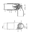
- FIG. 6 represents a sectional view through the dose counter shown in FIGS. 1 and 2 assembled
- FIG. 7A represents a front elevation of a press-and-breathe inhaler incorporating the dose counter illustrated in FIGS. 1 , 2 and 6
- FIG. 7B represents a cross-section along the line A-A shown in FIG. 7A
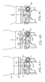
- FIGS. 8A to 8C are diagrammatic views showing the interaction between the aerosol valve and certain components of the dose counter illustrated in FIGS. 1 , 2 , and 6 during the firing stroke of the aerosol valve of the inhaler of FIG. 7 ,
- FIGS. 9A to 9C are diagrams showing the interaction between the aerosol valve of the inhaler and certain components of the dose counter illustrated in FIGS. 1 , 2 , and 6 during the return stroke of the aerosol valve of the inhaler of FIG. 7 , and
- FIG. 10A represents a horizontal cross-section through a drive nut assembled onto part of an annular member in the form of a drive wheel
- FIG. 10B represents a perspective view of a drive nut assembled onto such a drive wheel.
- FIGS. 1 , 2 and 6 illustrate an embodiment of a dose counter ( 1 ) in accordance with the invention, in particular one suitable for use with an inhaler. Terms such as ‘vertical’ or ‘top’ are to be read with reference to the orientation shown in FIG. 6 .
- the dose counter can be desirably provided as a stand alone unit with parts assembled onto a chassis ( 2 ).
- the illustrated dose counter comprises an annular member in the form of a drive wheel ( 4 ), a drive nut ( 6 ) and an actuator in the form of a flexible member ( 10 ).
- the illustrated dose counter also comprises an indexing arm base ( 8 ) onto which one end of the flexible member ( 10 ) is held in place via loose engagement.
- the illustrated dose counter further includes an indicator ring ( 12 ) linked to the drive wheel ( 4 ) for rotation therewith.
- the chassis ( 2 ), shown best in FIGS. 1 and 2 , is shaped like a shallow bowl with a raised hollow central cylindrical boss ( 202 ) having a central hole ( 204 ), so that a circular trough ( 206 ) is formed in the bowl.
- the trough has two circumferential slots ( 208 , 210 ); their position corresponds to those of two circumferential slots adjacent the cutaway segment of the indexing arm base, which will be described later.
- the chassis has two downwardly extending legs ( 212 , 214 ) shaped to fix the counter stably in an adapter of an inhaler in such a position as not to interfere with the spray and to permit actuation of the counter by downward movement of the aerosol unit.
- One of the legs ( 212 ) supports a cradle ( 216 ) that is formed out of part of the circumference of the bowl which is slightly lower than the rest of the bowl.
- the other leg ( 214 ) supports part of the trough diametrically opposite the cradle.
- the first leg ( 212 ) is wider and extends to a position corresponding to the side of the inside entrance to the mouthpiece of the inhaler adapter that is opposite that occupied by the second leg.
- the central circular boss ( 202 ) has a vertical segment cut away apart from a remaining central vertical rib ( 218 ).
- a small radial slot ( 220 ) cut away from the boss just to one side of the vertical segment extends outwards from just outside the central hole, and locates onto a rib at the rear of the inhaler actuator nozzle block.
- Two small circumferential slots are cut away from the foot of the boss, a first slot ( 222 ) that is just to one side (the side which is opposite to the radial slot ( 220 )) of the cut away vertical segment, and a second slot ( 224 ) diametrically opposite the first.
- the bowl has three upwardly extending posts ( 226 , 228 , 230 ) and an upwardly extending flange ( 232 ) positioned outside its circumference and attached thereto.
- the upwardly extending posts are positioned to limit undue flexing of the indicator ring ( 12 ).
- Two of the upwardly extending posts ( 228 , 230 ) are close together and between them at the bottom lies a circumferential beam ( 229 ), divided at its middle by a gap ( 231 ) just large enough to locate on an internal rib at the back the inhaler actuator.
- the flange ( 232 ) has an upper surface ( 234 ) to engage the innermost edge of the upper inside surface of the actuator mouthpiece. From the trough two ratchet fingers or pawls ( 236 , 238 ) extend upwards and slightly outwards from near the ends of the vertical segment.
- the rim of the bowl has a circumferential rebate ( 240 ) extending in parts of the rim that are spaced from the three upwardly extending posts, the upwardly extending flange and the cradle.
- the annular member having a helical thread segment formed about a circumferential arc on a part of its surface is provided in the form of a drive wheel.
- “circumferential arc” is taken to mean an arc of the circle that runs around, in a circumferential direction, the centre line or the approximate centre line of the annular member.
- FIG. 3B showing a sectional view of the drive wheel of the exemplary embodiment
- the general position of the centre line is marked as 450
- FIG. 10A the circumferential arc is indicated with a dotted line.
- 3A and 3B is an almost complete arc of a torus having grooves ( 402 ) shaped similar to parts of an external helix to define a helical thread segment disposed around the outer surface in a similar position to that of the tread on a tyre.
- the inner surface is cut away to form a protruding circumferential rim ( 404 ) projecting towards the centre, to provide two points of contact with the ends of the inner bore of a drive nut described later.
- On one end ( 406 ) of the arc of the torus is an orthogonally arranged stepped plate ( 408 ) with an upwardly extending stylus ( 410 ).
- the plate ( 408 ) has a wedge-shaped feature ( 412 ) extending further from the end of the arc of the torus and into the region where there is a split ( 414 ) in the torus.
- a circle of eight outward pointing ratchet teeth ( 608 ) are disposed on the circumference of the cylinder on each end section, the teeth on one circle having the same angles as the corresponding teeth on the other circle.
- the central section has a smooth cylindrical surface level with the apices of the ratchet teeth as shown at ( 610 ).
- the cylindrical component has an axial bore ( 612 ) and the internal surface so formed has a protruding helical rib ( 614 ) in the form of a single helical turn of oblong cross-section that extends along about half the length of the drive nut and is positioned centrally along its length.
- FIG. 4B representing a cross section along the line B-B in FIG. 4A shows the leading ( 618 ) and trailing ( 620 ) edges of the rib as it would be seen behind the cross section.
- FIG. 4C showing a cross section along line C-C shown in FIG.
- the helical form of the leading part of the rib continues so as to link with the trailing part of the rib.
- a rib having a single helical turn i.e. one that extends for no more than 360° round, e.g. the inner bore of, the drive nut
- the internal helical rib is easily provided by injection moulding, without the need for screw-off release from the moulding tooling.
- the provision and use of such a single turn is favourable in that the chance that moulding dimensional variations and tolerances might cause problems with the accuracy of interaction between the drive nut ( 6 ) and the drive wheel ( 4 ) is reduced or essentially minimized.
- the drive nut ( 6 ) is assembled onto the drive wheel ( 4 ) by screwing it onto the end of the drive wheel without the stepped plate ( 416 ) (see FIG. 3A ). During assembly the drive nut will be screwed back again until it rests against the wedge-shaped feature ( 412 ) that is designed to position the drive nut for the start of counting. (In this start position, the drive nut is essentially bridging the gap ( 414 ) between the two ends of the drive wheel.) The drive wheel and drive nut assembly so formed will be located in the trough ( 206 ) of the chassis with the drive nut located in the cradle ( 216 ). This positioning allows substantially only the desired functional movement of the drive nut and drive wheel.
- each groove on the drive wheel is favourably engineered to correspond to the volume swept out by the helical rib on the drive nut as the drive wheel traverses the drive nut, except at the ends ( 418 ) of the grooves where some lead-in is provided to facilitate initial engagement with the rib.
- the interaction between the drive nut and drive wheel is designed to ensure that accurate and robust location of each component is provided, in order to ensure accurate counting of doses.
- the drive nut is desirably made of a rigid material for robustness, to ensure that the drive nut can rotate about the drive wheel whilst fitting closely enough for the rib ( 614 ) and a groove ( 402 ) to interact, the drive nut ( 6 ) is desirably shaped not to follow the curvature of the drive wheel.
- the drive nut be essentially cylindrical in form, as shown in FIG. 10A .
- the inside profile e.g.
- each groove is slightly flared at its extremities ( 626 ).
- the rib and groove radial profiles are generally constructed and arranged to avoid the possibility of them wedging, e.g. when two parts of the rib are simultaneously engaged with adjacent grooves, whilst still ensuring that the engagement is tight enough to prevent relative wobble.
- the annular member may be provided in the form of a drive wheel, again being an almost complete arc of a torus, having grooves shaped similarly to parts of an external helix to define a helical thread segment disposed around the inner surface of the drive wheel, the radially outer part of the surface of drive wheel being free of any helical thread segments.
- the indexing arm base ( 8 ), best illustrated in FIGS. 1 and 2 is made up of a circular section ( 802 ) with a cutaway segment ( 804 ), an open cylindrical section ( 806 ) and an inner wall section ( 860 ).
- the circular section has a central hole ( 810 ) large enough to accommodate the nose of the valve ferrule. It has three circumferential slots ( 812 , 814 , 816 ) positioned at 90 degree intervals from the cutaway segment. Upwardly extending hooks ( 818 , 820 ) with small outward barbs ( 822 , 824 ) are positioned on points of the circumference of the circular section corresponding to the centres of the two circumferential slots ( 812 , 814 ) adjacent the cutaway segment.
- a containing rim ( 826 ) is positioned on the part of the circumference corresponding to the other circumferential slot ( 816 ), having an inwardly extending flange ( 828 ) and a small outward barb ( 830 ) on its top.
- the two circumferential slots ( 812 , 814 ) adjacent the cutaway segment and the corresponding two circumferential slots ( 208 , 210 ) in the chassis are positioned radially inside the drive wheel, so that they provide a passage for the user to inhale air through the counter when installed in the inhaler actuator.
- Two small ramps ( 832 , 834 ) are positioned on the perimeter of the circular section about midway between the containing rim ( 826 ) and each upwardly extending hook ( 818 , 820 ).
- the open cylindrical section ( 806 ) is open at both ends and extends downwardly from the circular section. It has a flat side corresponding to the cutaway segment of the circular section apart from two parts ( 836 ) recessed either side of a small bridge ( 840 ) joining the two parts around a vertical groove ( 838 ) described later.
- the inner wall section ( 860 ) extends downwardly from an inner part of the cylindrical section and is similarly shaped to this part of the cylindrical section so that it has a gap ( 838 ) below the small bridge ( 840 ). It also has two diametrically opposite pairs of gaps ( 842 , 844 ) each surrounding a small section of wall ( 846 , 848 ) with inner barbs ( 850 , 852 ) at the ends, to clip into the corresponding small circumferential slots ( 222 , 224 ) in the chassis thereby fixing the indexing arm base to the chassis.
- Both such downwardly extending parts therefore accommodate, centrally to the cutaway segment of the circular section, an internal vertical groove ( 838 ).
- an internal vertical groove ( 838 ) provides space for the ratchet fingers ( 236 , 238 ) on the chassis to operate through those sections of the indexing arm base.
- the inner wall section ( 860 ), inner surface of the open cylindrical section ( 806 ) and vertical groove ( 838 ) are dimensioned to fit over the hollow raised central cylindrical boss ( 202 ) of the chassis and its vertical rib ( 218 ), so that the circular section retains the drive wheel.
- the actuator is desirably in the form of a flexible member ( 10 ) comprising two opposed thin arcuate members ( 902 , 904 ) spaced apart relative to a central vertical plane of symmetry and with their apices ( 906 , 908 ) positioned outwardly.
- Each apex has a short pier ( 910 , 912 ) extending inwardly, to increase the land area for engagement with the valve ferrule of the aerosol container.
- each end of each arcuate member is joined to a respective end of the other arcuate member at the front, by a drive structure ( 914 ) comprising two fingers or nibs ( 916 , 918 ), one on either side of a bearing surface ( 920 ), and at the rear by a horizontal beam ( 922 ) having a section ( 924 ) cut away from the rear. Being joined at both ends confers stability to the thin arcuate members.
- the bearing surface ( 920 ) is arranged on the underside of a rectangular bridge ( 926 ) with parapets ( 928 , 930 ), the nibs ( 916 , 918 ) being at the feet of the parapets where they meet the feet of the arches.
- the nibs are sharp by design to engage the ratchet teeth ( 608 ) on the drive nut ( 6 ).
- the bearing surface ( 920 ) is designed to engage the smooth cylindrical surface ( 606 ) of the drive nut.
- the horizontal beam ( 922 ) is held in place by loose engagement with the inwardly extending flange ( 828 ) of the containing rim ( 826 ) and by the two ramps ( 832 , 834 ) on the indexing arm base ( 8 ).
- Indicia providing an indication of the number of doses dispensed or remaining may be provided on the radially outer surface of the drive wheel.
- indicia could be appropriately provided between the helical thread segments.
- the dose counter may be provided with an indicator ring.
- the indicator ring ( 12 ) is essentially ring-shaped (see FIGS. 1 and 2 ). It comprises a small outer rim ( 950 ) extending outwards at the bottom and an inner rim ( 952 ) extending inwards about half way up the inside surface. There are two short downward ribs ( 954 , 956 ) a small distance apart extending from the inner rim. The downward ribs are designed to contain the upwardly extending stylus ( 410 ) of the drive wheel ( 4 ), which consequently drives the indicator ring round as it moves. The inner rim is designed to be engaged by the three outward barbs ( 822 , 824 , 830 ) of the indexing arm base.
- the indicator ring ( 12 ) is prevented from flexing away from this engagement by the three posts ( 226 , 228 , 230 ) and the flange ( 232 ) upwardly extending from the chassis ( 2 ).
- the outer surface ( 958 ) of the indicator ring is typically provided with indicia (not shown).
- FIG. 6 provides an illustration of a sectional view through the assembled dose counter.
- the assembled dose counter can be placed in the body of an aerosol adapter ( 962 ) which comprises a sleeve ( 964 ), mouthpiece ( 966 ) and nozzle block ( 968 ) having an aperture ( 970 ) to accommodate the valve stem ( 972 ) of the valve ( 974 ) of an aerosol vial ( 976 ).
- the dose counter ( 1 ) generally is positioned within the adapter so that the nozzle block is accommodated within the central hole ( 204 ) of the chassis with the legs ( 212 , 214 ) of the chassis positioned either side of the spray path from the nozzle block to the mouthpiece.
- a window ( 960 ) may be positioned in the vertical section of the inhaler adapter to the user's left near the join between its sleeve and mouthpiece sections, so that a short length of the outer surface of the indicator ring of the dose counter together with the indicia provided on the indicator ring are visible therethrough.
- the window may be positioned elsewhere round the inhaler adapter.
- the aerosol adapter is of substantially conventional design for a press-and-breathe inhaler.
- FIGS. 8 and 9 provide diagrammatic views showing the interaction between the aerosol valve ( 974 ), in particular the valve ferrule ( 978 ), and certain components of the dose counter, in particular the flexible member ( 10 ), and the drive nut ( 6 ), during the firing stroke ( FIGS. 8B and 8C ) and during the return stroke ( FIGS. 9A and 9B ) and at rest prior to the firing stroke ( FIG. 8A ) and after the return stroke ( FIG. 9C ).
- the complete dose counter is not drawn, nor is the aerosol adapter. Movement of the respective components is represented by arrows in the Figures.
- valve ferrule ( 978 ) moving downwardly with the aerosol vial ( 976 ), engages the apices ( 906 , 908 , the latter not visible) and piers ( 910 , 912 , not visible) of the flexible arcuate members ( 902 , 904 , the latter not visible) ( FIG. 8B ) and pushes the flexible arcuate members downwards ( FIGS. 8B to 8C ).
- the flexible member is held at one end by a loose engagement with the indexing arm base (not shown), the downward pressure causes the flexible arcuate members to flatten, causing the bearing surface ( 920 ) of the flexible member to move over the smooth central surface ( 606 ) of the drive nut ( 6 ) and the nibs ( 916 , 918 , the latter not visible) of the flexible member to engage with a tooth ( 608 ) on each side of the drive nut to rotate the drive nut about its axis ( FIG. 8B to FIG. 8C ).
- the drive nut is driven slightly beyond a point at which the ratchet fingers ( 236 , 238 , the latter not visible) on the chassis ride over the ratchet teeth ( 608 - 2 ) two positions behind the ratchet teeth ( 608 ) engaged by the nibs of the flexible member. (Compare FIGS. 8A and 8B .)
- the use of a bearing surface of the flexible member positioned to bear on the central cylindrical portion of the drive nut is advantageous in this regard, because the nibs of the flexible member are thus guided into a more tangential motion against the ratchet, reducing the angle at which the nibs operate against the ratchet and hence helping to overcome frictional force. It will also be appreciated that if excess reciprocal motion of the aerosol vial occurs (e.g. due to valve dimensional tolerance ranges), it can readily be absorbed by the dose counter mechanism, as further motion of the nibs ( 916 , 918 , the latter not shown) may continue in a largely horizontal direction without significant unwanted further rotation of the drive nut.
- the axial movement of the drive nut is converted, by engagement of the helical rib ( 614 ) of the drive nut with the grooves ( 402 ) of the helical thread segment of the drive wheel ( 4 ), to rotational movement of the drive wheel ( 4 ) about its axis, which then, by engagement of the upwardly extending stylus ( 410 ) of the drive wheel with the ribs ( 954 , 956 ) of the indicator ring ( 12 ), drives the indicator ring ( 12 ) round a short distance.
- the aerosol vial ( 976 ) After firing a dose of medicament, e.g. when the user releases manual pressure on the inhaler, the aerosol vial ( 976 ) will return to its rest position ( FIGS. 9A through 9B to 9 C) under the influence of its valve's internal return spring ( 990 , shown in FIG. 7B ) causing an upward movement of the valve ferrule ( 978 ) and allowing the flexible arcuate members ( 902 , 904 , the latter not visible) to return to their former shape until finally the valve ferrule disengages completely from the apices ( 906 , 908 , the latter not visible) of the flexible arcuate members ( FIG. 9C ).
- the angle between the ratchet fingers and the ratchet teeth surfaces against which they ride, and the force applied by the ratchet fingers are typically designed such that the drive nut is allowed to move slightly in reverse and/or the ratchet fingers drive the drive nut slightly in reverse until the fingers rest in a gullet of the ratchet teeth of the drive nut (again, compare FIGS. 9A and 9B ) preventing further back rotation of the drive nut during the remaining movement of the flexible arcuate members back to their rest position ( FIG. 9C ).
- Components of devices may be made of plastics material, particularly thermoplastics material, and may be produced by injection moulding.
- the indicator ring, chassis, drive nut and drive wheel and indexing arm base may be constructed of rigid plastics materials.
- the resiliently flexible portion of the flexible member may be constructed of an appropriate plastics material e.g. polypropylene or polybutylterephthalate (PBT).
- PBT polybutylterephthalate
- the flexible member may optionally be made from more than one material, for example by two shot moulding. For example, a fairly flexible plastic material may be used for the flexible arcuate members ( 902 , 904 ) and a different, more rigid, plastic may be use for other parts of the flexible member ( 10 ).
- the flexible member may be made by insert moulding of plastic parts onto a metal wire frame.
- the dimensions and thicknesses of the flexible member, along with the choice of materials for different parts of it to achieve the desired flexibility, resilience or rigidity, may be selected to optimise the force characteristics and thereby optimise reliable counting.
- the materials and design may be selected to optimise the component's elasticity (recovery of shape) properties and their functional use. For example by making the flexible member of sufficiently thin arcuate sections, it can be rigid enough due to its arch-like shape to convey enough force to rotate the drive nut and drive wheel and, if applicable, an indicator ring through life, yet collapse when a (atypical) greater force is applied, such as in situations where the user needs to dispense a dose in an emergency or panic situation.
- the dose counter device may be designed such that when the device indicates the end of life of the inhaler, the drive nut may be tight against the stepped plate on the drive wheel so that further relative motion is prevented, which prevents further rotation of the drive nut.
- the flexible member is designed to collapse or crush down when the user attempts to dispense further doses, even though the dose counter or indicator indicates the end of life of the inhaler, the counting device does not prevent further doses being dispensed if any doses are still remaining in the inhaler.
- Dose counter devices described herein are advantageous in that existing inhaler designs can be easily retrofitted with such counter devices with only a minimum of changes to the design of the inhaler itself (generally simply the inclusion of a viewing window in the adapter and possibly dose counter retention clipping features). Additionally, dose counter devices described herein are robust and much more “tolerance-insensitive” than previously proposed inhaler counting devices. Also dose counting devices described herein are attractive due to their versatile design in that these dose counting devices can be easily modified for a broad range of different inhalers often by changing a single component, the flexible member. This is also advantageous in terms of development costs and resources as well as manufacturing costs (stocking, processing, logistics etc).
Landscapes
- Health & Medical Sciences (AREA)
- Engineering & Computer Science (AREA)
- Life Sciences & Earth Sciences (AREA)
- Biomedical Technology (AREA)
- Hematology (AREA)
- Bioinformatics & Cheminformatics (AREA)
- Pulmonology (AREA)
- Anesthesiology (AREA)
- Veterinary Medicine (AREA)
- Heart & Thoracic Surgery (AREA)
- Public Health (AREA)
- General Health & Medical Sciences (AREA)
- Animal Behavior & Ethology (AREA)
- General Physics & Mathematics (AREA)
- Theoretical Computer Science (AREA)
- Physics & Mathematics (AREA)
- Biophysics (AREA)
- Containers And Packaging Bodies Having A Special Means To Remove Contents (AREA)
Applications Claiming Priority (3)
| Application Number | Priority Date | Filing Date | Title |
|---|---|---|---|
| GB0706405.8 | 2007-04-02 | ||
| GBGB0706405.8A GB0706405D0 (en) | 2007-04-02 | 2007-04-02 | Dose counter |
| PCT/US2008/054833 WO2008121459A1 (fr) | 2007-04-02 | 2008-02-25 | Compteur de dose |
Publications (2)
| Publication Number | Publication Date |
|---|---|
| US20100229855A1 US20100229855A1 (en) | 2010-09-16 |
| US8459253B2 true US8459253B2 (en) | 2013-06-11 |
Family
ID=38050692
Family Applications (1)
| Application Number | Title | Priority Date | Filing Date |
|---|---|---|---|
| US12/593,812 Active 2029-10-08 US8459253B2 (en) | 2007-04-02 | 2008-02-25 | Dose counter |
Country Status (4)
| Country | Link |
|---|---|
| US (1) | US8459253B2 (fr) |
| EP (1) | EP2131904B1 (fr) |
| GB (1) | GB0706405D0 (fr) |
| WO (1) | WO2008121459A1 (fr) |
Cited By (12)
| Publication number | Priority date | Publication date | Assignee | Title |
|---|---|---|---|---|
| US20120241527A1 (en) * | 2009-12-09 | 2012-09-27 | 3M Innovation Properties Company | Dose indicator |
| US10124131B2 (en) | 2010-05-18 | 2018-11-13 | Ivax Pharmaceuticals Ireland | Dose counter for inhaler having an anti-reverse rotation actuator |
| US10434269B2 (en) | 2009-07-30 | 2019-10-08 | Ivax International B.V. | Dose counter for a metered-dose inhaler |
| US10643118B2 (en) | 2014-12-10 | 2020-05-05 | Alfred Von Schuckmann | Handheld device with a counter and counter |
| US11877848B2 (en) | 2021-11-08 | 2024-01-23 | Satio, Inc. | Dermal patch for collecting a physiological sample |
| US11964121B2 (en) | 2021-10-13 | 2024-04-23 | Satio, Inc. | Mono dose dermal patch for pharmaceutical delivery |
| US12023156B2 (en) | 2021-10-13 | 2024-07-02 | Satio, Inc. | Dermal patch for collecting a physiological sample |
| US12029562B2 (en) | 2021-04-14 | 2024-07-09 | Satio, Inc. | Dermal patch system |
| US12048543B2 (en) | 2021-11-08 | 2024-07-30 | Satio, Inc. | Dermal patch for collecting a physiological sample with removable vial |
| US12053284B2 (en) | 2021-11-08 | 2024-08-06 | Satio, Inc. | Dermal patch for collecting a physiological sample |
| US12178979B2 (en) | 2021-10-13 | 2024-12-31 | Satio, Inc. | Dermal patch for delivering a pharmaceutical |
| US12214346B2 (en) | 2021-10-13 | 2025-02-04 | Satio, Inc. | Dermal patch with a diagnostic test strip |
Families Citing this family (10)
| Publication number | Priority date | Publication date | Assignee | Title |
|---|---|---|---|---|
| JP2010537787A (ja) * | 2007-09-07 | 2010-12-09 | ディバーシー・インコーポレーテッド | 物質供給システムと方法 |
| FR2944902B1 (fr) * | 2009-04-28 | 2011-12-30 | Valois Sas | Compteur pour dispositif de distribution de produit fluide ou pulverulent. |
| CA2769248C (fr) | 2009-07-30 | 2014-03-11 | Ivax International B.V. | Element d'entrainement pivotant dans un dispositif doseur pour inhalateur |
| EP2459258B1 (fr) | 2009-07-30 | 2014-01-08 | Ivax International B.v. | Compteur de doses pour aérosol-doseur |
| FR2961186B1 (fr) * | 2010-06-11 | 2012-07-13 | Valois Sas | Dispositif de distribution de produit fluide. |
| GB201215917D0 (en) * | 2012-09-06 | 2012-10-24 | 3M Innovative Properties Co | Improvements in or relating to dose indicators |
| DE102016106875A1 (de) * | 2016-04-13 | 2017-10-19 | Alfred Von Schuckmann | Handgerät zur Ausgabe einer pharmazeutischen Substanz sowie Zählwerk für ein solches Handgerät |
| US11986589B2 (en) | 2018-09-27 | 2024-05-21 | Shl Medical Ag | Dose counting mechanism for an aerosol dispenser |
| CN109529161A (zh) * | 2019-01-08 | 2019-03-29 | 中山市美捷时包装制品有限公司 | 一种蜗杆计数型气雾剂吸入给药促动器 |
| CN114558210B (zh) * | 2022-03-04 | 2023-11-07 | 上海华瑞气雾剂有限公司 | 一种带有喷雾次数指示的驱动器及方法 |
Citations (32)
| Publication number | Priority date | Publication date | Assignee | Title |
|---|---|---|---|---|
| US4668218A (en) | 1985-04-12 | 1987-05-26 | Aktiebolaget Draco | Indicating means for a dosage dispensing device |
| GB2191032A (en) | 1986-04-25 | 1987-12-02 | Glaxo Group Ltd | Indicating device |
| EP0480488A1 (fr) | 1990-10-09 | 1992-04-15 | ELETTRO PLASTICA S.p.A. | Dispositif de comptage de doses pour un doseur des produits liquides, plus particulièrement pour usage pharmaceutique |
| WO1993021980A1 (fr) | 1992-05-05 | 1993-11-11 | Astra Aktiebolag | Inhalation doseur a elements indicateur et d'arret |
| US5349945A (en) | 1990-11-26 | 1994-09-27 | Minnesota Mining And Manufacturing Company | Aerosol dispenser comprising an indicator assembly |
| WO1996039337A1 (fr) | 1995-06-06 | 1996-12-12 | Senetics, Inc. | Dispositif indicateur actionne par une force axiale |
| US5870117A (en) | 1997-01-21 | 1999-02-09 | Xerox Corporation | Liquid ink printer including a camming printhead to enable increased resolution printing |
| US5871007A (en) | 1997-06-09 | 1999-02-16 | Chase Marketing International L.L.C. | Throat spray counting mechanism |
| US5988496A (en) | 1994-06-10 | 1999-11-23 | Valois S.A. | Dose counter for inhalers |
| GB2348928A (en) | 1999-04-07 | 2000-10-18 | Bespak Plc | Dose counter for pressurised container |
| US6446627B1 (en) | 1996-12-20 | 2002-09-10 | Norton Healthcare Limited | Inhaler dose counter |
| WO2002091293A1 (fr) | 2001-05-01 | 2002-11-14 | Ml Laboratories Plc | Mecanisme de comptage |
| US20020170928A1 (en) | 2001-05-15 | 2002-11-21 | Jerry Grychowski | Medicament applicator |
| US20020189611A1 (en) | 1999-09-08 | 2002-12-19 | Greenwood Mark H. | Inhalation counter device |
| US20020195102A1 (en) | 1997-06-10 | 2002-12-26 | Rand Paul Kenneth | Dispenser with doses' counter |
| US6655381B2 (en) | 2000-06-23 | 2003-12-02 | Ivax Corporation | Pre-metered dose magazine for breath-actuated dry powder inhaler |
| WO2004013582A1 (fr) | 2002-07-29 | 2004-02-12 | Valois Sas | Indicateur de doses pour dispositif de distribution de produit fluide |
| US20040065326A1 (en) | 2001-01-04 | 2004-04-08 | Macmichael Donald Bruce Atherton | Delivery device |
| US6752153B1 (en) | 1998-08-14 | 2004-06-22 | Rpc Wiko Gmbh & Co. Kg | Inhalator comprising a dosage counting device |
| US20050087191A1 (en) | 2003-10-28 | 2005-04-28 | Robert Morton | Indicating device with warning dosage indicator |
| US20050126469A1 (en) | 2003-12-15 | 2005-06-16 | Lu Winston Z. | Dose indicating device |
| WO2005084736A2 (fr) | 2004-03-08 | 2005-09-15 | Friedrich Sanner Gmbh & Co. Kg | Pulverisateur destine a la delivrance d'une dose de matieres pulverisables, notamment a l'application de principes actifs pharmaceutiques pulverulents |
| WO2006004498A1 (fr) | 2004-07-05 | 2006-01-12 | Astrazeneca Ab | Inhalateur reduisant le risque d'erreur de calcul des doses |
| WO2006027313A1 (fr) | 2004-09-04 | 2006-03-16 | Alfred Von Schuckmann | Inhalateur |
| WO2006054083A1 (fr) | 2004-11-19 | 2006-05-26 | Clinical Designs Limited | Distributeur de substance |
| WO2006062450A1 (fr) | 2004-12-10 | 2006-06-15 | Ernst Hörlins Ingenjösbyra Ab | Indicateur de doses pour inhalateur a doses |
| US7156258B2 (en) | 2002-06-12 | 2007-01-02 | Boehringer Ingelheim Microparts Gmbh | Counter for counting metered doses of liquid, pastry or solid products and device for the metered dispensing of such products |
| US7195134B2 (en) | 2001-02-23 | 2007-03-27 | Bespak Plc | Dosage counting devices |
| US7819075B2 (en) * | 2005-04-14 | 2010-10-26 | Astrazeneca Ab | Inhaler device counter |
| US8074643B2 (en) * | 1998-05-05 | 2011-12-13 | Trudell Medical International | Dispensing device |
| US8157128B2 (en) * | 1998-01-16 | 2012-04-17 | Trudell Medical International | Indicating device |
| US8181591B1 (en) * | 2008-05-23 | 2012-05-22 | Trudell Medical International | Domed actuator for indicating device |
-
2007
- 2007-04-02 GB GBGB0706405.8A patent/GB0706405D0/en not_active Ceased
-
2008
- 2008-02-25 WO PCT/US2008/054833 patent/WO2008121459A1/fr not_active Ceased
- 2008-02-25 US US12/593,812 patent/US8459253B2/en active Active
- 2008-02-25 EP EP08743541.8A patent/EP2131904B1/fr not_active Not-in-force
Patent Citations (33)
| Publication number | Priority date | Publication date | Assignee | Title |
|---|---|---|---|---|
| US4668218A (en) | 1985-04-12 | 1987-05-26 | Aktiebolaget Draco | Indicating means for a dosage dispensing device |
| GB2191032A (en) | 1986-04-25 | 1987-12-02 | Glaxo Group Ltd | Indicating device |
| EP0480488A1 (fr) | 1990-10-09 | 1992-04-15 | ELETTRO PLASTICA S.p.A. | Dispositif de comptage de doses pour un doseur des produits liquides, plus particulièrement pour usage pharmaceutique |
| US5349945A (en) | 1990-11-26 | 1994-09-27 | Minnesota Mining And Manufacturing Company | Aerosol dispenser comprising an indicator assembly |
| WO1993021980A1 (fr) | 1992-05-05 | 1993-11-11 | Astra Aktiebolag | Inhalation doseur a elements indicateur et d'arret |
| US5988496A (en) | 1994-06-10 | 1999-11-23 | Valois S.A. | Dose counter for inhalers |
| WO1996039337A1 (fr) | 1995-06-06 | 1996-12-12 | Senetics, Inc. | Dispositif indicateur actionne par une force axiale |
| US6446627B1 (en) | 1996-12-20 | 2002-09-10 | Norton Healthcare Limited | Inhaler dose counter |
| US5870117A (en) | 1997-01-21 | 1999-02-09 | Xerox Corporation | Liquid ink printer including a camming printhead to enable increased resolution printing |
| US5871007A (en) | 1997-06-09 | 1999-02-16 | Chase Marketing International L.L.C. | Throat spray counting mechanism |
| US20020195102A1 (en) | 1997-06-10 | 2002-12-26 | Rand Paul Kenneth | Dispenser with doses' counter |
| US8157128B2 (en) * | 1998-01-16 | 2012-04-17 | Trudell Medical International | Indicating device |
| US8074643B2 (en) * | 1998-05-05 | 2011-12-13 | Trudell Medical International | Dispensing device |
| US6752153B1 (en) | 1998-08-14 | 2004-06-22 | Rpc Wiko Gmbh & Co. Kg | Inhalator comprising a dosage counting device |
| GB2348928A (en) | 1999-04-07 | 2000-10-18 | Bespak Plc | Dose counter for pressurised container |
| US6907876B1 (en) | 1999-04-07 | 2005-06-21 | Bespak Plc | Dispensing apparatus comprising a dosage counting device |
| US20020189611A1 (en) | 1999-09-08 | 2002-12-19 | Greenwood Mark H. | Inhalation counter device |
| US6655381B2 (en) | 2000-06-23 | 2003-12-02 | Ivax Corporation | Pre-metered dose magazine for breath-actuated dry powder inhaler |
| US20040065326A1 (en) | 2001-01-04 | 2004-04-08 | Macmichael Donald Bruce Atherton | Delivery device |
| US7195134B2 (en) | 2001-02-23 | 2007-03-27 | Bespak Plc | Dosage counting devices |
| WO2002091293A1 (fr) | 2001-05-01 | 2002-11-14 | Ml Laboratories Plc | Mecanisme de comptage |
| US20020170928A1 (en) | 2001-05-15 | 2002-11-21 | Jerry Grychowski | Medicament applicator |
| US7156258B2 (en) | 2002-06-12 | 2007-01-02 | Boehringer Ingelheim Microparts Gmbh | Counter for counting metered doses of liquid, pastry or solid products and device for the metered dispensing of such products |
| WO2004013582A1 (fr) | 2002-07-29 | 2004-02-12 | Valois Sas | Indicateur de doses pour dispositif de distribution de produit fluide |
| US20050087191A1 (en) | 2003-10-28 | 2005-04-28 | Robert Morton | Indicating device with warning dosage indicator |
| US20050126469A1 (en) | 2003-12-15 | 2005-06-16 | Lu Winston Z. | Dose indicating device |
| WO2005084736A2 (fr) | 2004-03-08 | 2005-09-15 | Friedrich Sanner Gmbh & Co. Kg | Pulverisateur destine a la delivrance d'une dose de matieres pulverisables, notamment a l'application de principes actifs pharmaceutiques pulverulents |
| WO2006004498A1 (fr) | 2004-07-05 | 2006-01-12 | Astrazeneca Ab | Inhalateur reduisant le risque d'erreur de calcul des doses |
| WO2006027313A1 (fr) | 2004-09-04 | 2006-03-16 | Alfred Von Schuckmann | Inhalateur |
| WO2006054083A1 (fr) | 2004-11-19 | 2006-05-26 | Clinical Designs Limited | Distributeur de substance |
| WO2006062450A1 (fr) | 2004-12-10 | 2006-06-15 | Ernst Hörlins Ingenjösbyra Ab | Indicateur de doses pour inhalateur a doses |
| US7819075B2 (en) * | 2005-04-14 | 2010-10-26 | Astrazeneca Ab | Inhaler device counter |
| US8181591B1 (en) * | 2008-05-23 | 2012-05-22 | Trudell Medical International | Domed actuator for indicating device |
Non-Patent Citations (1)
| Title |
|---|
| Form PCT/ISA/210, International Search Report from WO 2008/121459. |
Cited By (16)
| Publication number | Priority date | Publication date | Assignee | Title |
|---|---|---|---|---|
| US10434269B2 (en) | 2009-07-30 | 2019-10-08 | Ivax International B.V. | Dose counter for a metered-dose inhaler |
| US20120241527A1 (en) * | 2009-12-09 | 2012-09-27 | 3M Innovation Properties Company | Dose indicator |
| US8814035B2 (en) * | 2009-12-09 | 2014-08-26 | 3M Innovative Properties Company | Dose indicator |
| US10124131B2 (en) | 2010-05-18 | 2018-11-13 | Ivax Pharmaceuticals Ireland | Dose counter for inhaler having an anti-reverse rotation actuator |
| US11395889B2 (en) | 2010-05-18 | 2022-07-26 | Ivax Pharmaceuticals Ireland | Dose counter for inhaler having an anti-reverse rotation actuator |
| US10643118B2 (en) | 2014-12-10 | 2020-05-05 | Alfred Von Schuckmann | Handheld device with a counter and counter |
| US12029562B2 (en) | 2021-04-14 | 2024-07-09 | Satio, Inc. | Dermal patch system |
| US12023156B2 (en) | 2021-10-13 | 2024-07-02 | Satio, Inc. | Dermal patch for collecting a physiological sample |
| US11964121B2 (en) | 2021-10-13 | 2024-04-23 | Satio, Inc. | Mono dose dermal patch for pharmaceutical delivery |
| US12178979B2 (en) | 2021-10-13 | 2024-12-31 | Satio, Inc. | Dermal patch for delivering a pharmaceutical |
| US12214346B2 (en) | 2021-10-13 | 2025-02-04 | Satio, Inc. | Dermal patch with a diagnostic test strip |
| US11877848B2 (en) | 2021-11-08 | 2024-01-23 | Satio, Inc. | Dermal patch for collecting a physiological sample |
| US12048543B2 (en) | 2021-11-08 | 2024-07-30 | Satio, Inc. | Dermal patch for collecting a physiological sample with removable vial |
| US12053284B2 (en) | 2021-11-08 | 2024-08-06 | Satio, Inc. | Dermal patch for collecting a physiological sample |
| US12440133B2 (en) | 2021-11-08 | 2025-10-14 | Satio, Inc. | Dermal patch for collecting a physiological sample |
| US12446810B2 (en) | 2021-11-08 | 2025-10-21 | Satio, Inc. | Dermal patch for collecting a physiological sample |
Also Published As
| Publication number | Publication date |
|---|---|
| WO2008121459A1 (fr) | 2008-10-09 |
| US20100229855A1 (en) | 2010-09-16 |
| EP2131904A4 (fr) | 2013-11-06 |
| EP2131904A1 (fr) | 2009-12-16 |
| GB0706405D0 (en) | 2007-05-09 |
| EP2131904B1 (fr) | 2016-04-06 |
Similar Documents
| Publication | Publication Date | Title |
|---|---|---|
| US8459253B2 (en) | Dose counter | |
| KR101625162B1 (ko) | 카운터 | |
| US10022509B2 (en) | Dose counter for inhaler having a bore and shaft arrangement | |
| US10792444B2 (en) | Dose indicator or dose counter | |
| CN105246525B (zh) | 分配器 | |
| EP3127049B1 (fr) | Compteur de doses pour inhalateur à doses comptées | |
| CN103987417B (zh) | 分配器 | |
| CN106132467A (zh) | 用于计量剂量吸入器的剂量指示器 | |
| KR102111137B1 (ko) | 카운터 | |
| AU2016203060B2 (en) | Dose counters for inhalers, inhalers and shafts thereof |
Legal Events
| Date | Code | Title | Description |
|---|---|---|---|
| AS | Assignment |
Owner name: 3M INNOVATIVE PROPERTIES COMPANY, MINNESOTA Free format text: ASSIGNMENT OF ASSIGNORS INTEREST;ASSIGNOR:HOWGILL, STEPHEN J.;REEL/FRAME:024306/0558 Effective date: 20100422 |
|
| STCF | Information on status: patent grant |
Free format text: PATENTED CASE |
|
| FPAY | Fee payment |
Year of fee payment: 4 |
|
| AS | Assignment |
Owner name: KINDEVA DRUG DELIVERY L.P., MINNESOTA Free format text: ASSIGNMENT OF ASSIGNORS INTEREST;ASSIGNORS:3M COMPANY;3M INNOVATIVE PROPERTIES COMPANY;REEL/FRAME:052818/0234 Effective date: 20200422 |
|
| AS | Assignment |
Owner name: MIDCAP FINANCIAL TRUST, AS ADMINISTRATIVE AGENT, MARYLAND Free format text: SECURITY INTEREST;ASSIGNOR:KINDEVA DRUG DELIVERY L.P.;REEL/FRAME:053586/0715 Effective date: 20200501 |
|
| MAFP | Maintenance fee payment |
Free format text: PAYMENT OF MAINTENANCE FEE, 8TH YEAR, LARGE ENTITY (ORIGINAL EVENT CODE: M1552); ENTITY STATUS OF PATENT OWNER: LARGE ENTITY Year of fee payment: 8 |
|
| AS | Assignment |
Owner name: KINDEVA DRUG DELIVERY L.P., MINNESOTA Free format text: TERMINATION AND RELEASE OF SECURITY INTEREST IN PATENT COLLATERAL RECORDED AT R/F 053586/0715;ASSIGNOR:MIDCAP FINANCIAL TRUST, AS ADMINISTRATIVE AGENT;REEL/FRAME:062115/0707 Effective date: 20221212 |
|
| AS | Assignment |
Owner name: JPMORGAN CHASE BANK, N.A., AS COLLATERAL AGENT, ILLINOIS Free format text: SECURITY INTEREST;ASSIGNOR:KINDEVA DRUG DELIVERY L.P.;REEL/FRAME:062122/0618 Effective date: 20221212 |
|
| MAFP | Maintenance fee payment |
Free format text: PAYMENT OF MAINTENANCE FEE, 12TH YEAR, LARGE ENTITY (ORIGINAL EVENT CODE: M1553); ENTITY STATUS OF PATENT OWNER: LARGE ENTITY Year of fee payment: 12 |