US8464762B2 - Straw packaging machine - Google Patents
Straw packaging machine Download PDFInfo
- Publication number
- US8464762B2 US8464762B2 US12/677,002 US67700208A US8464762B2 US 8464762 B2 US8464762 B2 US 8464762B2 US 67700208 A US67700208 A US 67700208A US 8464762 B2 US8464762 B2 US 8464762B2
- Authority
- US
- United States
- Prior art keywords
- housings
- straws
- belt
- filling
- conveyor element
- Prior art date
- Legal status (The legal status is an assumption and is not a legal conclusion. Google has not performed a legal analysis and makes no representation as to the accuracy of the status listed.)
- Expired - Fee Related, expires
Links
Images


Classifications
-
- A—HUMAN NECESSITIES
- A61—MEDICAL OR VETERINARY SCIENCE; HYGIENE
- A61D—VETERINARY INSTRUMENTS, IMPLEMENTS, TOOLS, OR METHODS
- A61D19/00—Instruments or methods for reproduction or fertilisation
- A61D19/02—Instruments or methods for reproduction or fertilisation for artificial insemination
- A61D19/022—Containers for animal semen, e.g. pouches or vials ; Methods or apparatus for treating or handling animal semen containers, e.g. filling or closing
- A61D19/024—Tube-like containers, e.g. straws
Definitions
- the present invention concerns the packaging of predetermined doses of liquid substance in straw.
- straws are packaging units formed of a thin plastic material tube the inside diameter of which is in particular sufficiently small for the dose of liquid substance to be retained in place by capillary action and a stopper engaged in the thin tube near one end.
- the conveyor device of such a machine is formed of a pair of identical conveyor belts designed for straws of a particular diameter (like the belts shown in FIGS. 1 and 2 for two different straw diameters). These belts are disposed at a distance from each other and each is provided with a succession of housings for receiving said straws, these housings being disposed according to a predetermined pitch (that is to say the distance separating the distances between centers of two successive housings) equal to the predetermined distance between the filling stations to be able to place each straw in a group of four in alignment with a corresponding filling station (that is to say between a corresponding suction nozzle and a corresponding filling nozzle).
- a predetermined pitch that is to say the distance separating the distances between centers of two successive housings
- Filling is effected by a movement toward each other of the filling and suction nozzles toward the straws which are then filled simultaneously. Once the latter straws have been filled, the belts are moved by a distance equal to four times the pitch referred to above in order to place four new empty straws beside the four straws that have just been filled between the corresponding filling and suction nozzles, the filled straws being then conveyed to the welding unit.
- the invention aims to provide a machine of the same type but more convenient at the same time as remaining economical and retaining good performance.
- a machine for packaging straws of a predetermined diameter including a filling unit for said straws including n filling stations, n being an integer number equal to at least 1, and a conveyor device for said straws for disposing n straws each in line with one of said filling stations, said device having at least one conveyor element provided with a succession of receiving housings for said straws disposed according to a predetermined pitch, said conveyor element being adapted to be moved, after each filling of n straws, a distance equal to n times said predetermined pitch to dispose n new straws next to the preceding n straws, each in line with one of said filling stations, characterized in that said conveyor element includes, in addition to said succession of receiving housings for said straws, referred to as first housings, a succession of receiving housings for straws of another predetermined diameter, referred to as second housings, said second housings being disposed according to said pitch, each of said second receiving housings being disposed between two of said first receiving housings.
- the conveyor device of the machine of the invention is rendered compatible with straws of different diameters, for example straws of small diameter and large diameter, without having to replace the conveyor element.
- the machine When the machine is used with straws of small diameter, the latter straws are disposed in the appropriate housings. The same applies when the machine is used with straws of large diameter except that in this case the straws are received in the other housings.
- the interleaving of the housings for straws of different diameters also preserves for a given length of the conveyor element the same number of straws of the same diameter that can be conveyed by that element as for the conveyor elements of the prior art machine.
- the density of straws of the same diameter i.e. the number of straws of the same diameter per unit length
- the space separating two identical housings is exploited to interleave supplementary housings (for straws of different diameter). It is therefore in particular not necessary to lengthen the conveyor element.
- n is equal to at least 2
- said predetermined pitch of said conveyor element is equal to said predetermined gap
- the machine of the invention is particularly polyvalent because it packages straws of different diameters at low additional cost.
- the pitch separating two identical housings being preserved regardless of the type of housing and chosen to be equal to the predetermined distance between two filling stations, with the first and second housings that are interleaved with each other, the conveyor device of the machine of the invention thus leads to no major change in the configuration of the prior art machine, the machine of the invention remaining compatible with existing straw filling and welding stations as well as with the mechanism for moving the conveyor element.
- said conveyor element includes a belt in which are provided first gutters of predetermined diameter forming said first housings and second gutters of another predetermined diameter forming said second housings.
- said conveyor element includes a first belt and a second belt disposed side-by-side, said first housings belonging to said first belt, said second housings belonging to said second belt.
- said first belt is offset by half said pitch relative to said second belt and there are provided in said first belt, between said first housings, grooves situated in line with said second housings of said second belt and there are provided in said second belt, between said second housings, grooves situated in line with said first housings of said first belt.
- the conveyor device of the machine of the invention can thus be produced from two conventional belts by machining those belts to form the corresponding grooves therein and moving these belts by half of one pitch relative to each other, each straw thus being accommodated in a corresponding housing and in a groove aligned with that housing.
- said grooves are crenellated grooves
- each of said conveyor elements has on the side opposite said housings a succession of teeth
- said device includes, in addition to said conveyor element, referred to as the first element, a second conveyor element identical to and parallel to said first conveyor element and spaced from said first conveyor element by a distance less than the length of said straws to be packaged; and/or
- each filling station includes, on respective opposite sides of the conveyor device, a suction nozzle and a filling nozzle for the liquid to be introduced into said straws.
- FIGS. 1 and 2 are two views in elevation showing two prior art conveyor belt portions respectively designed to receive straws of small diameter and straws of large diameter;
- FIG. 3 is a view similar to FIGS. 1 and 2 but showing a conveyor belt portion of a machine of the invention
- FIG. 4 is a perspective view of part of this machine in which are represented four filling stations disposed side-by-side and a conveyor device provided with two conveyor elements, here two belts as shown in FIG. 3 , disposed parallel and in which straws of small diameter are engaged;
- FIG. 5 is a view similar to FIG. 4 except that in this case it is straws of large diameter that are engaged in the two belts;
- FIGS. 6 and 7 are two views showing, for straws of large diameter and straws of small diameter, respectively, a second embodiment of the machine of the invention in which the conveyor elements are arranged differently;
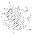
- FIG. 8 is a view to a larger scale of the detail marked VIII in FIG. 7 .
- the machine as shown partly in FIGS. 4 and 5 comprises a certain number of equipment units necessary for packaging initially empty straws.
- the straws are straws of which the stopper (not shown) includes two porous plugs and between those plugs a volume of gel powder, that is to say powder that is transformed into a gel in contact with an aqueous liquid, but the machine of the invention can of course be used for other types of straws, particularly with stoppers of different design.
- This machine 1 includes a fixed frame (not shown) supporting a removable and interchangeable hopper (not shown) containing a batch of empty small straws 11 of the order of 2 mm in diameter ( FIG. 4 ), or empty large straws 12 , of the order of 3 mm in diameter ( FIG. 5 ), a conveyor device 2 for these straws, a filling unit 3 including four filling stations 4 for filling the straws with semen, a welding unit including four welding stations (not shown), for example ultrasound welding stations, for welding the ends of the straws once filled, and, finally, a receptacle for receiving filled and welded straws (also not shown).
- the distribution hopper that is not shown is a parallelepiped-shaped box with an open top for loading into it a batch of empty straws and delivering the straws one-by-one to the conveyor device 2 .
- the unit 3 includes four filling stations 4 disposed side-by-side at a predetermined distance, each filling station 4 being provided with a suction nozzle 6 and a filling nozzle 7 .
- the filling and suction nozzles are respectively connected to a flask of semen, not shown, and to a vacuum source, also not shown, by means of flexible pipes.
- the conveyor device 2 includes two conveyor elements 5 spaced from each other by a distance less than the length of a straw and a mechanism for driving rotation of these elements including a hub driven by a motor (not shown).
- Each conveyor element 5 is formed of a belt 8 having a first succession of receiving housings 15 for straws such as 11 (straws of small diameter) and a succession of receiving housings 16 for straws such as 12 (straws of large diameter).
- the housings 15 are disposed according to a predetermined pitch E (distance between the distances between centers of two successive identical housings) equal to the predetermined distance between the filling stations 4 , and the same applies to the housings 16 , each housing 16 being disposed half-way between two housings 15 .
- the belts 8 cooperate with the hub of the drive mechanism via a series of teeth 13 situated on the side opposite the housings 15 and 16 .
- each housing 15 has the shape of a gutter 18 (respectively 19 ) in the hollow of which a straw of the corresponding diameter is received.
- the conveyor device 2 is also provided, for each belt, with an element 20 for guiding these belts.
- the straws initially stored in the hopper are distributed by that hopper into the corresponding housings of the belts where those belts are curved, in the vicinity of the guide elements 20 , the curvature of the belts opening the housings 15 and 16 to facilitate the loading of the straws.
- the dimensions of the housings (respectively 16 ) are chosen so that the straws 11 (respectively 12 ) that are housed therein are held immobile in those housings after loading in order for the subsequent filling step to be carried out under good conditions, particularly on insertion of the suction and filling nozzles into the straws.
- the motor is controlled so that the belts move so as to convey the straws, in groups of four, to the filling unit 3 where each straw of this group is aligned with a corresponding filling station 4 .
- the nozzles 6 and 7 are moved with a movement that is the converse of the movement effected to nest them in the straws so as to disengage the end portions of these straws.
- the motor of the conveyor device is then driven to move the belts in the direction of the arrow A by a distance equal to four times the pitch E in order to dispose new empty straws in the filling unit 3 and to dispose the four straws of the group of straws that have just been filled in the welding unit (not shown), this station including four welding stations with the same predetermined pitch E as the filling stations, each straw that has just been filled being aligned with a corresponding welding station to be welded there.
- the motor of the conveyor device is then driven again to move the belts in the direction of the arrow A by a distance equal to four times the pitch E in order to move the welded straws to an accessory of the machine (not shown) for disengaging the straws from their housings so that they drop into a storage receptacle.
- FIGS. 6 to 8 Another embodiment of the machine of the invention is shown in FIGS. 6 to 8 .
- each conveyor element 105 consists not of a belt 8 but of a pair of belts 109 and 110 disposed side-by-side and each derived from a prior art belt (similar to those shown in FIGS. 1 and 2 ) by machining.
- the belts 109 of each element 105 are disposed opposite each other relative to the belts 110 of these elements.
- each belt 109 is obtained from a prior art belt similar to the belt 9 shown in FIG. 1 (except that the flared portions 23 of the belt 9 are not present in the belt 109 ) in which have been produced by machining crenellated grooves 121 between the housings 115 receiving the straws so that this modified belt 109 has a succession of receiving housings 115 of gutter shape for straws 11 of small diameter and between those housings a succession of crenellated grooves 121 for receiving therein straws 12 of large diameter.
- each belt 110 is obtained from a prior art belt similar to the belt 10 shown in FIG. 2 (except that the flared portions 24 of the belt 10 are not present in the belt 110 ) in which there have been produced by machining crenellated grooves 122 between the housings 116 for receiving straws so that this modified belt 110 has a succession of housings 116 of gutter shape for straws 12 of large diameter and between these housings a succession of crenellated grooves 122 for receiving therein straws 11 of small diameter.
- the housings 115 of the belt 109 are offset by one half-pitch, i.e. E/2 ( FIG. 8 ), relative to the housings 116 of the belt 110 alongside this belt so that the housings 115 are aligned with the groove 122 and the housings 116 are aligned with the grooves 121 .
- each straw 12 of large diameter is accommodated in a crenellation 121 of one belt 109 and in a housing 116 of a belt 110 of the first conveyor element 105 as well as in a housing 116 of a belt 110 and in a crenellation 121 of a belt 109 of the second conveyor element 105 .
- each straw 11 of small diameter is accommodated in a housing 115 of a belt 109 and in a crenellation 122 of a belt 110 of the first conveyor element 105 and then in a crenellation 122 of a belt 110 and in a housing 115 of a belt 109 of the second conveyor element 105 .
- the motor and the hub of this embodiment of the machine do not in this case drive the two belts 8 but the two pairs of belts 109 and 110 via the teeth 113 of those belts, this embodiment of the machine advantageously enabling reuse of the conventional belts.
- the belts 8 , 109 and 110 have for each housing flared portions similar to the portions 23 and 24 of the belts 9 and 10 ( FIGS. 1 and 2 ) adapted to center and to guide the straws toward the interior of the housings.
- the belts of the machine are replaced by any other conveyor element having a similar arrangement, such as a single belt, a drum, a grooved mat or one or more notched disks.
- the number n of filling stations is other than four, n being equal to at least one.
- the conveyor elements of the invention are adapted to receive straws not of two different diameters but of three or more than three different diameters, the successions of housings for each type of straw alternating, two successive identical housings still being separated by a pitch E, two successive housings of different types being then in this case separated by a distance equal to E/p where p corresponds to the number of types of straws of different diameter that can be received in these conveyor elements.
Landscapes
- Health & Medical Sciences (AREA)
- Veterinary Medicine (AREA)
- Life Sciences & Earth Sciences (AREA)
- General Health & Medical Sciences (AREA)
- Wood Science & Technology (AREA)
- Zoology (AREA)
- Animal Behavior & Ethology (AREA)
- Reproductive Health (AREA)
- Public Health (AREA)
- Engineering & Computer Science (AREA)
- Basic Packing Technique (AREA)
- Auxiliary Devices For And Details Of Packaging Control (AREA)
- Formation And Processing Of Food Products (AREA)
- Accessories For Mixers (AREA)
- Disintegrating Or Milling (AREA)
- Sorting Of Articles (AREA)
- Manufacturing And Processing Devices For Dough (AREA)
Applications Claiming Priority (3)
| Application Number | Priority Date | Filing Date | Title |
|---|---|---|---|
| FR0757438A FR2920750B1 (fr) | 2007-09-07 | 2007-09-07 | Machine de conditionnement de paillettes |
| FR0757438 | 2007-09-07 | ||
| PCT/FR2008/051574 WO2009044043A1 (fr) | 2007-09-07 | 2008-09-04 | Machine de conditionnement de paillettes |
Publications (2)
| Publication Number | Publication Date |
|---|---|
| US20100200113A1 US20100200113A1 (en) | 2010-08-12 |
| US8464762B2 true US8464762B2 (en) | 2013-06-18 |
Family
ID=39248217
Family Applications (1)
| Application Number | Title | Priority Date | Filing Date |
|---|---|---|---|
| US12/677,002 Expired - Fee Related US8464762B2 (en) | 2007-09-07 | 2008-09-04 | Straw packaging machine |
Country Status (7)
| Country | Link |
|---|---|
| US (1) | US8464762B2 (de) |
| EP (1) | EP2200534B1 (de) |
| AT (1) | ATE500799T1 (de) |
| DE (1) | DE602008005486D1 (de) |
| DK (1) | DK2200534T3 (de) |
| FR (1) | FR2920750B1 (de) |
| WO (1) | WO2009044043A1 (de) |
Cited By (1)
| Publication number | Priority date | Publication date | Assignee | Title |
|---|---|---|---|---|
| US10407192B2 (en) | 2015-06-02 | 2019-09-10 | Imv Technologies | Straw filling device and machine comprising same |
Families Citing this family (4)
| Publication number | Priority date | Publication date | Assignee | Title |
|---|---|---|---|---|
| FR2905592B1 (fr) * | 2006-09-13 | 2008-11-28 | Eurl Cryo Vet Entpr Unipersonn | "machine pour remplir de semence des paillettes d'insemination artificielle" |
| FR3064173B1 (fr) * | 2017-03-24 | 2019-05-03 | Imv Technologies | Installation de traitement de paillettes de conditionnement de semence animale, comportant un dispositif d'alimentation et de positionnement desdites paillettes |
| JPWO2020166105A1 (de) * | 2019-02-14 | 2020-08-20 | ||
| CN114348321B (zh) * | 2022-01-26 | 2023-08-04 | 江苏集萃药康生物科技股份有限公司 | 一种动物遗传物质自动装管设备 |
Citations (5)
| Publication number | Priority date | Publication date | Assignee | Title |
|---|---|---|---|---|
| US2094524A (en) * | 1936-12-28 | 1937-09-28 | George H Busch | Evacuating machine |
| US3931661A (en) | 1974-08-08 | 1976-01-13 | Tur-Colossus, Inc. | Apparatus for cleaning and disinfecting insemination straws |
| FR2680101A1 (fr) | 1991-08-07 | 1993-02-12 | Cassou Robert | Buse d'injection a usage unique pour machine de remplissage de paillettes, notamment pour l'insemination artificielle d'animaux et conservation de produits biologiques. |
| DE20100106U1 (de) | 2001-01-04 | 2001-04-05 | Basf Ag, 67063 Ludwigshafen | Fördervorrichtung |
| EP1125870A1 (de) | 2000-01-31 | 2001-08-22 | IMV Technologies | Maschine zum Fördern und Zuführen von Röhrchen an eine Stelle, insbesondere Pailletten |
Family Cites Families (1)
| Publication number | Priority date | Publication date | Assignee | Title |
|---|---|---|---|---|
| CH533542A (fr) * | 1971-08-25 | 1973-02-15 | Geneco | Appareil pour remplir des tubes d'un liquide |
-
2007
- 2007-09-07 FR FR0757438A patent/FR2920750B1/fr not_active Expired - Fee Related
-
2008
- 2008-09-04 EP EP08836331A patent/EP2200534B1/de not_active Not-in-force
- 2008-09-04 DE DE602008005486T patent/DE602008005486D1/de active Active
- 2008-09-04 DK DK08836331.2T patent/DK2200534T3/da active
- 2008-09-04 WO PCT/FR2008/051574 patent/WO2009044043A1/fr not_active Ceased
- 2008-09-04 US US12/677,002 patent/US8464762B2/en not_active Expired - Fee Related
- 2008-09-04 AT AT08836331T patent/ATE500799T1/de not_active IP Right Cessation
Patent Citations (7)
| Publication number | Priority date | Publication date | Assignee | Title |
|---|---|---|---|---|
| US2094524A (en) * | 1936-12-28 | 1937-09-28 | George H Busch | Evacuating machine |
| US3931661A (en) | 1974-08-08 | 1976-01-13 | Tur-Colossus, Inc. | Apparatus for cleaning and disinfecting insemination straws |
| FR2680101A1 (fr) | 1991-08-07 | 1993-02-12 | Cassou Robert | Buse d'injection a usage unique pour machine de remplissage de paillettes, notamment pour l'insemination artificielle d'animaux et conservation de produits biologiques. |
| US5249610A (en) | 1991-08-07 | 1993-10-05 | Robert Cassou | Single-use injector nozzle for straw filling machine, in particular for artificial insemination of animals and storage of biological products |
| EP1125870A1 (de) | 2000-01-31 | 2001-08-22 | IMV Technologies | Maschine zum Fördern und Zuführen von Röhrchen an eine Stelle, insbesondere Pailletten |
| US6732486B2 (en) | 2000-01-31 | 2004-05-11 | Imv Technologies | Machine for conveying and moving into position tubes, in particular straws |
| DE20100106U1 (de) | 2001-01-04 | 2001-04-05 | Basf Ag, 67063 Ludwigshafen | Fördervorrichtung |
Cited By (1)
| Publication number | Priority date | Publication date | Assignee | Title |
|---|---|---|---|---|
| US10407192B2 (en) | 2015-06-02 | 2019-09-10 | Imv Technologies | Straw filling device and machine comprising same |
Also Published As
| Publication number | Publication date |
|---|---|
| EP2200534B1 (de) | 2011-03-09 |
| FR2920750A1 (fr) | 2009-03-13 |
| ATE500799T1 (de) | 2011-03-15 |
| EP2200534A1 (de) | 2010-06-30 |
| DE602008005486D1 (de) | 2011-04-21 |
| DK2200534T3 (da) | 2011-06-20 |
| FR2920750B1 (fr) | 2010-03-12 |
| US20100200113A1 (en) | 2010-08-12 |
| WO2009044043A1 (fr) | 2009-04-09 |
Similar Documents
| Publication | Publication Date | Title |
|---|---|---|
| US8464762B2 (en) | Straw packaging machine | |
| ES2372483T3 (es) | Método y aparato para agrupar productos asépticos. | |
| EP1160165B1 (de) | Vorrichtung zum Formen von Zigarettengruppen | |
| JPH0427089B2 (de) | ||
| US8925289B2 (en) | Machine for filling artificial insemination straws with semen | |
| US3435940A (en) | Mechanism for the formation of orderly groups of cigarettes | |
| US9549876B2 (en) | Device for introducing filling material into capsules | |
| US6385947B2 (en) | Method of and apparatus for accumulating and manipulating arrays of cigarettes and the like | |
| JPH0255290B2 (de) | ||
| US3772848A (en) | Method and machine for packaging rod shaped articles | |
| AU688747B2 (en) | Method and apparatus for feeding, grouping and orientating articles | |
| CN106562472B (zh) | 用于输送并储存加工业的棒形的和/或方形的产品的装置和方法 | |
| US3448846A (en) | Apparatus for assembling batches of rod-shaped articles | |
| US6578344B1 (en) | Apparatus for charging tubular canisters with a stack of flat, disk-shaped items, particularly potato chips | |
| ES2216098T3 (es) | Procedimiento y maquina para la fabricacion de paquetes de cigarrillos. | |
| US4476665A (en) | Packaging machine | |
| US6347709B1 (en) | Method and apparatus for transferring packing units | |
| CS210612B2 (en) | Device for forming of groups of products | |
| HU223680B1 (hu) | Csomagolóberendezés zacskók gyűjtőcsomagolására és eljárás zacskók gyűjtőtartályba történő csomagolására | |
| CN110733696B (zh) | 一种烟包包装装置及方法 | |
| GB2097744A (en) | Packet handling apparatus | |
| JPH05139422A (ja) | 物品供給装置 | |
| US4406197A (en) | Method and apparatus for transporting rod-shaped articles | |
| JPS60148429A (ja) | 物品を包装し集合化する機械 | |
| US4135617A (en) | Article conveying mechanisms |
Legal Events
| Date | Code | Title | Description |
|---|---|---|---|
| AS | Assignment |
Owner name: IMV TECHNOLOGIES, FRANCE Free format text: ASSIGNMENT OF ASSIGNORS INTEREST;ASSIGNORS:TOUJAS, CLAUDE;BEAU, CHRISTIAN;REEL/FRAME:024050/0426 Effective date: 20081127 |
|
| STCF | Information on status: patent grant |
Free format text: PATENTED CASE |
|
| FPAY | Fee payment |
Year of fee payment: 4 |
|
| FEPP | Fee payment procedure |
Free format text: MAINTENANCE FEE REMINDER MAILED (ORIGINAL EVENT CODE: REM.); ENTITY STATUS OF PATENT OWNER: LARGE ENTITY |
|
| LAPS | Lapse for failure to pay maintenance fees |
Free format text: PATENT EXPIRED FOR FAILURE TO PAY MAINTENANCE FEES (ORIGINAL EVENT CODE: EXP.); ENTITY STATUS OF PATENT OWNER: LARGE ENTITY |
|
| STCH | Information on status: patent discontinuation |
Free format text: PATENT EXPIRED DUE TO NONPAYMENT OF MAINTENANCE FEES UNDER 37 CFR 1.362 |
|
| FP | Lapsed due to failure to pay maintenance fee |
Effective date: 20210618 |