US8608435B2 - Turbo engine - Google Patents
Turbo engine Download PDFInfo
- Publication number
- US8608435B2 US8608435B2 US12/514,283 US51428307A US8608435B2 US 8608435 B2 US8608435 B2 US 8608435B2 US 51428307 A US51428307 A US 51428307A US 8608435 B2 US8608435 B2 US 8608435B2
- Authority
- US
- United States
- Prior art keywords
- ring
- bellows
- casing
- curved walls
- disposed
- Prior art date
- Legal status (The legal status is an assumption and is not a legal conclusion. Google has not performed a legal analysis and makes no representation as to the accuracy of the status listed.)
- Expired - Fee Related, expires
Links
Images


Classifications
-
- F—MECHANICAL ENGINEERING; LIGHTING; HEATING; WEAPONS; BLASTING
- F01—MACHINES OR ENGINES IN GENERAL; ENGINE PLANTS IN GENERAL; STEAM ENGINES
- F01D—NON-POSITIVE DISPLACEMENT MACHINES OR ENGINES, e.g. STEAM TURBINES
- F01D11/00—Preventing or minimising internal leakage of working-fluid, e.g. between stages
- F01D11/08—Preventing or minimising internal leakage of working-fluid, e.g. between stages for sealing space between rotor blade tips and stator
- F01D11/14—Adjusting or regulating tip-clearance, i.e. distance between rotor-blade tips and stator casing
- F01D11/20—Actively adjusting tip-clearance
- F01D11/22—Actively adjusting tip-clearance by mechanically actuating the stator or rotor components, e.g. moving shroud sections relative to the rotor
-
- F—MECHANICAL ENGINEERING; LIGHTING; HEATING; WEAPONS; BLASTING
- F05—INDEXING SCHEMES RELATING TO ENGINES OR PUMPS IN VARIOUS SUBCLASSES OF CLASSES F01-F04
- F05D—INDEXING SCHEME FOR ASPECTS RELATING TO NON-POSITIVE-DISPLACEMENT MACHINES OR ENGINES, GAS-TURBINES OR JET-PROPULSION PLANTS
- F05D2250/00—Geometry
- F05D2250/60—Structure; Surface texture
- F05D2250/61—Structure; Surface texture corrugated
-
- F—MECHANICAL ENGINEERING; LIGHTING; HEATING; WEAPONS; BLASTING
- F05—INDEXING SCHEMES RELATING TO ENGINES OR PUMPS IN VARIOUS SUBCLASSES OF CLASSES F01-F04
- F05D—INDEXING SCHEME FOR ASPECTS RELATING TO NON-POSITIVE-DISPLACEMENT MACHINES OR ENGINES, GAS-TURBINES OR JET-PROPULSION PLANTS
- F05D2250/00—Geometry
- F05D2250/60—Structure; Surface texture
- F05D2250/61—Structure; Surface texture corrugated
- F05D2250/611—Structure; Surface texture corrugated undulated
Definitions
- the invention concerns a turbo engine, especially a gas turbine.
- the gap between the casing ring of the housing and the radially outward lying end of the rotating blade ring or each rotating blade ring can be adjusted or adapted in its size by servomechanisms to provide a so-called Active Clearance Control, so as to automatically influence the gap and ensure an optimal gap maintenance over all operating conditions.
- the radially inward lying housing wall or the casing ring is segmented in the circumferential direction, and preferably each segment is assigned a separate servomechanism.
- the servomechanisms are preferably electromechanical actuators.
- DE 101 17 231 A1 discloses a turbo engine with a stator and a rotor, wherein the gap between radially outward lying ends of the rotating blades and the radially inward lying housing wall can be adjusted by means of a pneumatic, i.e., pressurized air-operated, actuator unit of a rotor gap control module.
- the pneumatic actuator unit of the rotor gap control module disclosed there has an actuator chamber, a pressure chamber, and valves connecting the actuator chamber and the pressure chamber, and depending on the pressure prevailing in the actuator chamber sealing elements of the rotor gap control module are inflated so as to adjust or adapt the size of the gap between radially outward lying ends of rotating blades and the casing ring of the housing in the sense of a pneumatic Active Clearance Control.
- the turbo engine of DE 29 22 835 C2 has a stator and a rotor, while the gap between radially outward lying ends of the rotating blades and an inner ring or casing ring of a housing wall can be pneumatically adjusted.
- the casing ring is connected to a support ring via flexible sidewalls, with the casing ring, the support ring and the side walls forming a bellows-like structure.
- the flexible sidewalls of DE 29 22 835 C2 are curved several times. Accordingly, seen in the axial direction, the sidewalls of DE 29 22 835 C2 curve inward into the cavity for some segments and outward from the cavity for some segments.
- the problem of the present invention is to create a new kind of turbo engine with a pneumatic Active Clearance Control.
- a turbo engine wherein, in the region of the bellows-like structure or each bellows-like structure, the wall connecting the casing ring to the support ring is curved only once inwardly into the respective cavity, looking in the axial direction.
- a turbo engine wherein, in the region of the bellows-like structure or each bellows-like structure, the wall connecting the casing ring to the support ring is curved only once outwardly from the respective cavity, looking in the axial direction.
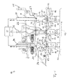
- FIG. 1 a cross section through subassemblies at the stator side of a turbo engine according to the invention
- FIG. 2 a schematic representation of a bellows-like structure of the turbine per FIG. 1 ;
- FIG. 3 a schematic representation of an alternative bellows-like structure of a turbo engine
- FIG. 4 a cross section of a turbo engine in according with an alternative embodiment.
- FIG. 1 shows a partial cross section through a stator of a compressor 10 of a turbo engine, wherein the stator comprises a housing 11 as well as several stationary guide blades 12 .
- the guide blades 12 on the stator side form so-called guide blade rings, which are arranged one behind the other looking in the axial direction.
- FIG. 1 shows a total of four stationary guide blade rings 13 , 14 , 15 and 16 at the stator side.
- the compressor 10 contains a rotor 40 not shown in FIG. 1 , the rotor being formed from several rotor disks, not shown, arranged one behind the other in axial direction 42 , each rotor disk carrying several rotating blades 44 , likewise not shown, alongside each other in the circumferential direction (see FIG 4 ).
- the rotating blades assigned to one rotor disk and arranged alongside each other in the circumferential direction form so-called rotating blade rings, while between every two neighboring guide blade rings 13 and 14 , 14 and 15 , and 15 and 16 , there is arranged a respective rotating blade ring 46 , not shown.
- the compressor 10 contains a rotor 40 not shown in FIG. 1 , the rotor being formed from several rotor disks, not shown, arranged one behind the other in axial direction 42 , each rotor disk carrying several rotating blades 44 , likewise not shown, alongside each other in the circumferential direction (see FIG. 4 ).
- the rotating blades assigned to one rotor disk and arranged alongside each other in the circumferential direction form so-called rotating blade rings 46 , while between every two neighboring guide blade rings 13 and 14 , 14 and 15 , and 15 and 16 , there is arranged a respective rotating blade ring 46 (see FIG. 4 ).
- the housing 11 of the stator of the compressor 10 comprises a radially inward lying housing wall, while the radially inward lying housing wall forms a so-called inner ring or casing ring in the region of each rotating blade ring 46 at the rotor side, not shown in FIG. 1 , and encloses the respective rotating blade ring 46 radially on the outside.
- the housing 11 further comprises a radially outward lying housing wall 18 .
- the radially inward lying housing wall forms a so-called casing ring 17 in the region of each rotating blade ring at the rotor side (not shown), which encloses the rotating blade ring radially on the outside.
- a radial gap 48 ( FIG. 4 ), which is subject to considerable changes during the operation of the compressor, since on the one hand the rotating blades and the respective casing rings have different thermal behavior and on the other hand the rotating blades undergo a change in length 50 due to the centrifugal forces at work during operation.
- the present invention concerns only those details which can be used to exactly maintain radial gaps between radially outward lying ends of rotating blade rings and the respective casing ring 17 .
- the casing rings 17 which extend between the guide blade rings 13 and 14 , as well as 15 and 16 , are connected by curved and elastically flexible walls 19 to a support ring 20 , the respective support ring 20 being arranged between the respective casing ring 17 and the radially outward lying housing wall 18 .
- the respective casing ring 17 , the support ring 20 , and the curved walls 19 extending between the respective casing ring 17 and the respective support ring 20 form a bellows-like structure 21 , having a cavity 22 .
- the bellows-like structure 21 and thus the cavity 22 fully surrounds and thereby encloses the rotating blade ring, looking in the circumferential direction.
- the gap 48 between the respective casing ring 17 and the radially outward lying end of the respective rotating blade ring 46 can be adjusted pneumatically. If the pressure is increased in the cavity 22 of the respective bellows-like structure 21 , the respective radially inward lying casing ring 17 can be forced radially inward and the respective radially outward lying support ring 20 radially outward. By reducing the pressure in the cavity 22 of the respective bellows-like structure 21 , an opposite deformation of the respective bellows-like structure 21 can be accomplished.
- the curved and elastically flexible walls 19 of the bellows-like structures 21 are curved only one time inward into the respective cavity 22 , looking in the axial direction. In the region of a vertex of the curve, wall segments of the respective wall 19 subtend a relatively obtuse angle ⁇ larger than 90 degrees. This is described hereafter in reference to FIG. 2 , which shows a schematic representation of a bellows-like structure 21 .
- FIG. 2 shows that in the region of a vertex 29 of the curve, the wall segments of the respective wall 19 subtend an obtuse angle ⁇ .
- ⁇ the wall segments of the respective wall 19 subtend an obtuse angle ⁇ .
- the respective casing ring 17 and the respective support ring 20 are forced apart, looking directly in the radial direction.
- this radial forcing apart of the casing ring 17 and support ring 20 is supported or at least not hindered by a toggle-like effect of the curved walls 19 .
- the curved walls 19 are essentially subjected only to compressive forces.
- the bellows-like structure 21 has a greater radial dimension than its axial dimension.
- the walls 19 of the bellows-like structure 21 have a greater radial dimension than their axial dimension.
- each bellows-like structure 21 has a roughly constant wall thickness, looking in the radial direction.
- the curved walls 19 it is also possible for the curved walls 19 to have a variable wall thickness, looking in the radial direction.
- each bellows-like structure 21 has a smaller wall thickness that the respective radially outward lying support ring 20 .
- the support ring 20 of each bellows-like structure 21 is accordingly designed with a greater wall thickness than the respective casing ring 17 . This ensures that deformations of the bellows-like structure 21 brought about by change of pressure prevailing in the particular cavity 22 act primarily on the casing ring 17 .
- each bellows-like structure 21 has a radially outward curved contour 23 , protruding into the respective cavity 22 , in a middle region, looking in the axial direction.
- an outer contour 28 of the casing ring 17 is displaced essentially only parallel, looking in the radial direction, so that a gap between the casing ring 17 and the rotating blade ring can be adjusted exactly.
- Each bellows-like structure 21 is coordinated with at least one pressurized air line 24 , in order to either bring pressurized air into the cavity 22 of the respective bellows-like structure 21 or drain pressurized air from it.
- FIG. 1 shows one such pressurized air line 24 only for the bellows-like structure 21 positioned between the two guide blade rings 13 and 14 , looking in the axial direction.
- Each bellows-like structure 21 is coordinated with at least one such pressurized air line 24 . The more such pressurized air lines 24 are present per bellows-like structure 21 , the quicker pressurized air can be taken to or drained from the respective cavity 24 .
- one bellows-like structure 21 is arranged between the two guide blade rings 13 and 14 , and also between the two guide blade rings 15 and 16 , while no such bellows-like structure is present between the two guide blade rings 14 and 15 .
- a sensor unit 25 is arranged between the two guide blade rings 14 and 15 and, thus, in the region of a rotating blade ring arranged between the former.
- the sensor unit 25 With the sensor unit 25 , one can measure at least the radial dimension of the gap 48 between the corresponding rotating blade ring 46 and the casing ring 17 surrounding this rotating blade ring. Via a signal line 26 , the sensor unit 25 transmits the corresponding actual value to a feedback control mechanism 52 ( FIG. 4 ) where the feedback control mechanism compares the actual value against a setpoint and, depending on this, adjusts the pressure prevailing in the cavities 22 of the bellows-like structures 21 so that the actual value comes near the setpoint.
- a feedback control mechanism 52 FIG. 4
- the pressurized air feed to the cavities 22 and the pressurized air drain from the cavities 22 of the bellows-like structures 21 can be adjusted by individual valves, in order to individually adjust the pressure prevailing in the cavities 22 of the two bellows-like structures 21 and thus individually adjust the dimension of the radial gap between the casing ring 17 and the corresponding rotating blade ring as a function of the respective radial dimension of the rotating blade ring.
- the profiles of the first curved walls 19 disposed between guide rings 13 and 14 are adapted to produce a different deformation of the associated bellows-like structure 21 (denoted by deformed casing ring 17 ′, shown in broken line) than the profiles of the second curved walls 19 disposed between guide rings 15 and 16 produce in the associated bellows-like structure 21 .
- the curvature of the curved walls 19 of the bellows-like structure 21 disposed between guide rings 13 and 14 is different (i.e., greater than) than the curvature of the curved walls 19 of the bellows-like structure 21 disposed between guide rings 15 and 16 .
- the wall thickness of the curved walls 19 of the bellows-like structure 21 disposed between guide rings 13 and 14 is different (i.e., less than) than the wall thickness of the curved walls 19 of the bellows-like structure 21 disposed between guide rings 15 and 16 .
- the two bellows-like structures 21 are divided in the axial direction by dividing planes extending in the radial direction, and the two axial halves of the bellows-like structures 21 are welded together during the fabrication process.
- each wall 19 in the region of each bellows-like structure 21 is curved only once inward into the respective cavity 22 , looking in the axial direction.
- each curved, elastically flexible wall 19 in the region of each bellows-like structure 30 is curved only once outward from the respective cavity 22 , looking in the axial direction.
- Wall segments of the respective wall 19 in the region of a vertex 29 of the curvature subtend a relatively acute angle ⁇ smaller than 90 degrees.
- the wall segments of the wall 19 subtending the angle ⁇ extend basically in the axial direction. Like the casing ring 17 and the support ring 21 , they are exposed to the pressure prevailing in the cavity 22 and thereby support a radial moving apart of the casing ring 17 and support ring 20 when pressure increases in the cavity 22 . A negative toggle effect in this variant is also totally eliminated by the acute angle ⁇ .
- the bellows-like structure 30 per FIG. 3 has a larger axial dimension than its radial dimension; in particular, the walls 19 of the bellows-like structure 30 have a larger axial dimension than their radial dimension.
Landscapes
- Engineering & Computer Science (AREA)
- Mechanical Engineering (AREA)
- General Engineering & Computer Science (AREA)
- Structures Of Non-Positive Displacement Pumps (AREA)
- Turbine Rotor Nozzle Sealing (AREA)
Applications Claiming Priority (5)
| Application Number | Priority Date | Filing Date | Title |
|---|---|---|---|
| DE102006052786A DE102006052786B4 (de) | 2006-11-09 | 2006-11-09 | Turbomaschine |
| EP102006052786.0 | 2006-11-09 | ||
| DE102006052786 | 2006-11-09 | ||
| DE102006052786.0 | 2006-11-09 | ||
| PCT/DE2007/001946 WO2008055474A1 (de) | 2006-11-09 | 2007-10-30 | Turbomaschine |
Publications (2)
| Publication Number | Publication Date |
|---|---|
| US20100003122A1 US20100003122A1 (en) | 2010-01-07 |
| US8608435B2 true US8608435B2 (en) | 2013-12-17 |
Family
ID=39167469
Family Applications (1)
| Application Number | Title | Priority Date | Filing Date |
|---|---|---|---|
| US12/514,283 Expired - Fee Related US8608435B2 (en) | 2006-11-09 | 2007-10-30 | Turbo engine |
Country Status (6)
| Country | Link |
|---|---|
| US (1) | US8608435B2 (de) |
| EP (1) | EP2087208B9 (de) |
| AT (1) | ATE497088T1 (de) |
| CA (1) | CA2666200A1 (de) |
| DE (2) | DE102006052786B4 (de) |
| WO (1) | WO2008055474A1 (de) |
Cited By (2)
| Publication number | Priority date | Publication date | Assignee | Title |
|---|---|---|---|---|
| US10794213B2 (en) * | 2016-06-21 | 2020-10-06 | Rolls-Royce North American Technologies Inc. | Blade tip clearance control for an axial compressor with radially outer annulus |
| US10851712B2 (en) | 2017-06-27 | 2020-12-01 | General Electric Company | Clearance control device |
Families Citing this family (3)
| Publication number | Priority date | Publication date | Assignee | Title |
|---|---|---|---|---|
| EP2218880A1 (de) * | 2009-02-16 | 2010-08-18 | Siemens Aktiengesellschaft | Aktives Spaltkontrollsystem für Gasturbinen |
| FR3024492B1 (fr) * | 2014-07-29 | 2019-08-23 | Safran Aircraft Engines | Element comprenant un stator et un rotor de turbomachine avec un joint d'etancheite et test de ce joint |
| CN113565637B (zh) * | 2021-07-27 | 2025-04-29 | 永旭腾风新能源动力科技(北京)有限公司 | 一种转动装置及燃气轮机 |
Citations (14)
| Publication number | Priority date | Publication date | Assignee | Title |
|---|---|---|---|---|
| FR2458676A1 (fr) | 1979-06-06 | 1981-01-02 | Mtu Muenchen Gmbh | Dispositif d'etancheite pour l'intervalle peripherique d'une turbomachine a flux axial |
| US4329114A (en) * | 1979-07-25 | 1982-05-11 | The United States Of America As Represented By The Administrator Of The National Aeronautics And Space Administration | Active clearance control system for a turbomachine |
| JPS5820904A (ja) | 1981-07-29 | 1983-02-07 | Hitachi Ltd | ガスタ−ビン動翼先端シ−ル構造 |
| US4472108A (en) * | 1981-07-11 | 1984-09-18 | Rolls-Royce Limited | Shroud structure for a gas turbine engine |
| JPS62142808A (ja) | 1985-12-18 | 1987-06-26 | Toshiba Corp | ガスタ−ビンの間隙制御装置 |
| US4683716A (en) * | 1985-01-22 | 1987-08-04 | Rolls-Royce Plc | Blade tip clearance control |
| GB2195715A (en) | 1986-10-08 | 1988-04-13 | Rolls Royce Plc | Rotor blade tip-shroud |
| US4784569A (en) * | 1986-01-10 | 1988-11-15 | General Electric Company | Shroud means for turbine rotor blade tip clearance control |
| US4971517A (en) * | 1988-12-27 | 1990-11-20 | Allied-Signal Inc. | Turbine blade clearance controller |
| US5048288A (en) * | 1988-12-20 | 1991-09-17 | United Technologies Corporation | Combined turbine stator cooling and turbine tip clearance control |
| US5211534A (en) | 1991-02-23 | 1993-05-18 | Rolls-Royce Plc | Blade tip clearance control apparatus |
| US5344284A (en) | 1993-03-29 | 1994-09-06 | The United States Of America As Represented By The Secretary Of The Air Force | Adjustable clearance control for rotor blade tips in a gas turbine engine |
| DE10117231A1 (de) | 2001-04-06 | 2002-10-31 | Hodson Howard | Rotorspalt-Steuermodul |
| DE102004037955A1 (de) | 2004-08-05 | 2006-03-16 | Mtu Aero Engines Gmbh | Turbomaschine, insbesondere Gasturbine |
Family Cites Families (3)
| Publication number | Priority date | Publication date | Assignee | Title |
|---|---|---|---|---|
| JPS5741407A (en) * | 1980-08-22 | 1982-03-08 | Hitachi Ltd | Sealing mechanism on top of turbine rotor blade |
| DE3830762C2 (de) * | 1988-09-09 | 1994-08-18 | Mtu Muenchen Gmbh | Einrichtung zur Halterung eines Mantelringes in Gasturbinen |
| US6918743B2 (en) * | 2002-10-23 | 2005-07-19 | Pratt & Whitney Canada Ccorp. | Sheet metal turbine or compressor static shroud |
-
2006
- 2006-11-09 DE DE102006052786A patent/DE102006052786B4/de not_active Expired - Fee Related
-
2007
- 2007-10-30 DE DE502007006392T patent/DE502007006392D1/de active Active
- 2007-10-30 US US12/514,283 patent/US8608435B2/en not_active Expired - Fee Related
- 2007-10-30 WO PCT/DE2007/001946 patent/WO2008055474A1/de not_active Ceased
- 2007-10-30 CA CA002666200A patent/CA2666200A1/en not_active Abandoned
- 2007-10-30 EP EP07846281A patent/EP2087208B9/de not_active Not-in-force
- 2007-10-30 AT AT07846281T patent/ATE497088T1/de active
Patent Citations (16)
| Publication number | Priority date | Publication date | Assignee | Title |
|---|---|---|---|---|
| FR2458676A1 (fr) | 1979-06-06 | 1981-01-02 | Mtu Muenchen Gmbh | Dispositif d'etancheite pour l'intervalle peripherique d'une turbomachine a flux axial |
| DE2922835C2 (de) | 1979-06-06 | 1985-06-05 | MTU Motoren- und Turbinen-Union München GmbH, 8000 München | Umfangsspaltdichtung an Axialströmungsmaschinen |
| US4329114A (en) * | 1979-07-25 | 1982-05-11 | The United States Of America As Represented By The Administrator Of The National Aeronautics And Space Administration | Active clearance control system for a turbomachine |
| US4472108A (en) * | 1981-07-11 | 1984-09-18 | Rolls-Royce Limited | Shroud structure for a gas turbine engine |
| JPS5820904A (ja) | 1981-07-29 | 1983-02-07 | Hitachi Ltd | ガスタ−ビン動翼先端シ−ル構造 |
| US4683716A (en) * | 1985-01-22 | 1987-08-04 | Rolls-Royce Plc | Blade tip clearance control |
| JPS62142808A (ja) | 1985-12-18 | 1987-06-26 | Toshiba Corp | ガスタ−ビンの間隙制御装置 |
| US4784569A (en) * | 1986-01-10 | 1988-11-15 | General Electric Company | Shroud means for turbine rotor blade tip clearance control |
| GB2195715A (en) | 1986-10-08 | 1988-04-13 | Rolls Royce Plc | Rotor blade tip-shroud |
| US4844688A (en) * | 1986-10-08 | 1989-07-04 | Rolls-Royce Plc | Gas turbine engine control system |
| US5048288A (en) * | 1988-12-20 | 1991-09-17 | United Technologies Corporation | Combined turbine stator cooling and turbine tip clearance control |
| US4971517A (en) * | 1988-12-27 | 1990-11-20 | Allied-Signal Inc. | Turbine blade clearance controller |
| US5211534A (en) | 1991-02-23 | 1993-05-18 | Rolls-Royce Plc | Blade tip clearance control apparatus |
| US5344284A (en) | 1993-03-29 | 1994-09-06 | The United States Of America As Represented By The Secretary Of The Air Force | Adjustable clearance control for rotor blade tips in a gas turbine engine |
| DE10117231A1 (de) | 2001-04-06 | 2002-10-31 | Hodson Howard | Rotorspalt-Steuermodul |
| DE102004037955A1 (de) | 2004-08-05 | 2006-03-16 | Mtu Aero Engines Gmbh | Turbomaschine, insbesondere Gasturbine |
Non-Patent Citations (1)
| Title |
|---|
| PCT/DE2007/001946, International Search Report and Written Opinion, Sep. 11, 2006. |
Cited By (2)
| Publication number | Priority date | Publication date | Assignee | Title |
|---|---|---|---|---|
| US10794213B2 (en) * | 2016-06-21 | 2020-10-06 | Rolls-Royce North American Technologies Inc. | Blade tip clearance control for an axial compressor with radially outer annulus |
| US10851712B2 (en) | 2017-06-27 | 2020-12-01 | General Electric Company | Clearance control device |
Also Published As
| Publication number | Publication date |
|---|---|
| WO2008055474A1 (de) | 2008-05-15 |
| DE102006052786B4 (de) | 2011-06-30 |
| EP2087208B9 (de) | 2012-04-25 |
| ATE497088T1 (de) | 2011-02-15 |
| EP2087208A1 (de) | 2009-08-12 |
| DE502007006392D1 (de) | 2011-03-10 |
| EP2087208B1 (de) | 2011-01-26 |
| DE102006052786A1 (de) | 2008-05-15 |
| CA2666200A1 (en) | 2008-05-15 |
| US20100003122A1 (en) | 2010-01-07 |
Similar Documents
| Publication | Publication Date | Title |
|---|---|---|
| US8292571B2 (en) | Apparatus and method for clearance control of turbine blade tip | |
| US8608427B2 (en) | Arrangement for optimising the running clearance for turbomachines | |
| US8240986B1 (en) | Turbine inter-stage seal control | |
| US5522697A (en) | Load reducing variable geometry turbine | |
| US8534996B1 (en) | Vane segment tip clearance control | |
| US8608435B2 (en) | Turbo engine | |
| US10309410B2 (en) | Impeller shroud with deflecting outer member for clearance control in a centrifugal compressor | |
| JP2006022814A (ja) | ブレードのクリアランスの制御 | |
| EP3249239B1 (de) | Lüfterradabdeckung mit pneumatischem kolben zur abstandssteuerung in einem zentrifugalverdichter | |
| GB2050524A (en) | Turbine stator shroud assembly | |
| US20170198709A1 (en) | Centrifugal compressor assembly for use in a turbine engine and method of assembly | |
| EP3172410B1 (de) | Leitschaufelanordnung in einem gasturbinentriebwerk | |
| US10794213B2 (en) | Blade tip clearance control for an axial compressor with radially outer annulus | |
| US7654791B2 (en) | Apparatus and method for controlling a blade tip clearance for a compressor | |
| US20160312636A1 (en) | Fluid seal structure of heat engine including steam turbine | |
| EP3542031B1 (de) | Schaufelanordnung für eine turbomaschine | |
| GB2259956A (en) | Turbomachine with variably settable stator blades | |
| US20050089401A1 (en) | Turbine blade tip clearance system | |
| GB2525240A (en) | Variable geometry turbine | |
| EP3794219B1 (de) | Schaufel- und deckbandanordnungen für eine turbomaschine | |
| CN115516189B (zh) | 用于涡轮发动机的密封组件 | |
| EP3530881B1 (de) | Turbine mit variabler geometrie | |
| JP2003139093A (ja) | 動翼の隙間調整機構及び軸流回転機械及び圧縮機 | |
| CN105840313A (zh) | 用于燃气涡轮发电装置的维修方法及套件 |
Legal Events
| Date | Code | Title | Description |
|---|---|---|---|
| AS | Assignment |
Owner name: MTU AERO ENGINES GMBH, GERMANY Free format text: ASSIGNMENT OF ASSIGNORS INTEREST;ASSIGNOR:BOCK, ALEXANDER;REEL/FRAME:022739/0924 Effective date: 20090404 |
|
| REMI | Maintenance fee reminder mailed | ||
| LAPS | Lapse for failure to pay maintenance fees |
Free format text: PATENT EXPIRED FOR FAILURE TO PAY MAINTENANCE FEES (ORIGINAL EVENT CODE: EXP.) |
|
| STCH | Information on status: patent discontinuation |
Free format text: PATENT EXPIRED DUE TO NONPAYMENT OF MAINTENANCE FEES UNDER 37 CFR 1.362 |
|
| STCH | Information on status: patent discontinuation |
Free format text: PATENT EXPIRED DUE TO NONPAYMENT OF MAINTENANCE FEES UNDER 37 CFR 1.362 |
|
| FP | Lapsed due to failure to pay maintenance fee |
Effective date: 20171217 |