US8622366B2 - Manually operable drive module - Google Patents
Manually operable drive module Download PDFInfo
- Publication number
- US8622366B2 US8622366B2 US12/877,151 US87715110A US8622366B2 US 8622366 B2 US8622366 B2 US 8622366B2 US 87715110 A US87715110 A US 87715110A US 8622366 B2 US8622366 B2 US 8622366B2
- Authority
- US
- United States
- Prior art keywords
- valve drive
- drive device
- magnetic field
- drive system
- hand
- Prior art date
- Legal status (The legal status is an assumption and is not a legal conclusion. Google has not performed a legal analysis and makes no representation as to the accuracy of the status listed.)
- Active, expires
Links
Images

Classifications
-
- F—MECHANICAL ENGINEERING; LIGHTING; HEATING; WEAPONS; BLASTING
- F16—ENGINEERING ELEMENTS AND UNITS; GENERAL MEASURES FOR PRODUCING AND MAINTAINING EFFECTIVE FUNCTIONING OF MACHINES OR INSTALLATIONS; THERMAL INSULATION IN GENERAL
- F16K—VALVES; TAPS; COCKS; ACTUATING-FLOATS; DEVICES FOR VENTING OR AERATING
- F16K31/00—Actuating devices; Operating means; Releasing devices
- F16K31/44—Mechanical actuating means
- F16K31/60—Handles
-
- F—MECHANICAL ENGINEERING; LIGHTING; HEATING; WEAPONS; BLASTING
- F16—ENGINEERING ELEMENTS AND UNITS; GENERAL MEASURES FOR PRODUCING AND MAINTAINING EFFECTIVE FUNCTIONING OF MACHINES OR INSTALLATIONS; THERMAL INSULATION IN GENERAL
- F16K—VALVES; TAPS; COCKS; ACTUATING-FLOATS; DEVICES FOR VENTING OR AERATING
- F16K37/00—Special means in or on valves or other cut-off apparatus for indicating or recording operation thereof, or for enabling an alarm to be given
- F16K37/0025—Electrical or magnetic means
- F16K37/0033—Electrical or magnetic means using a permanent magnet, e.g. in combination with a reed relays
-
- F—MECHANICAL ENGINEERING; LIGHTING; HEATING; WEAPONS; BLASTING
- F16—ENGINEERING ELEMENTS AND UNITS; GENERAL MEASURES FOR PRODUCING AND MAINTAINING EFFECTIVE FUNCTIONING OF MACHINES OR INSTALLATIONS; THERMAL INSULATION IN GENERAL
- F16K—VALVES; TAPS; COCKS; ACTUATING-FLOATS; DEVICES FOR VENTING OR AERATING
- F16K37/00—Special means in or on valves or other cut-off apparatus for indicating or recording operation thereof, or for enabling an alarm to be given
- F16K37/0025—Electrical or magnetic means
- F16K37/0041—Electrical or magnetic means for measuring valve parameters
Definitions
- the present invention relates to a valve drive system including a valve drive device and a hand-operated apparatus for triggering operating actions in the valve drive device.
- valve drives require either mechanical actuations by hand inside the valve drive device or complicated line-bound or wireless data transfer techniques (in particular radio and infrared are known in this area), or they are based on conventional possibilities of operation such as, e.g., the activation of keys which are covered by a front film.
- Opening a housing or removing a housing part in order to reach the inside of a valve drive device is awkward and time-consuming.
- line-bound technologies are expensive.
- Wireless data transfer, e.g. via modems, is also too costly for most applications.
- a control using keys is not always found to be convenient and requires reliable and, hence, expensive control panels.
- One objective of the invention is to allow a reliable and convenient operation of a valve drive device.
- a valve drive system includes a valve drive device and a hand-operated apparatus to trigger control actions in the valve drive device.
- the hand-operated apparatus includes a magnet arrangement
- the valve drive device includes a magnetic field sensor arrangement adjusted to the magnet arrangement of the hand-operated apparatus.
- a magnetic field sensor arrangement adjusted to the magnet arrangement of the hand-operated apparatus means a sensor arrangement which can register a magnetic field generated by the magnet arrangement when the magnet arrangement is in the vicinity of the magnetic field sensor arrangement.
- the valve drive system allows a safe triggering of control actions within the valve drive device. Opening the housing of the valve drive device is required just as little as any cabling, plug connections or interfaces for a wireless data transfer. In addition, this system is virtually free of wear since the triggering of control actions takes place in a contactless manner. Handling is very comfortable, with no keys having to be pressed; it is only necessary to bring the hand-operated apparatus near the valve drive device and, if required, move the hand-operated apparatus. When realizing the magnetic field arrangement and the associated magnetic field sensor arrangement, use may be made of standard components to the greatest possible extent so that, in comparison with other technologies, the subject system is cost-effective.
- the magnetic field sensor arrangement of the valve drive device is preferably designed to be sensitive to the field strength and/or the field direction of the magnetic field generated by the magnet arrangement.
- Embodiments in which the magnetic field sensor arrangement includes at least two sensors and/or the magnet arrangement includes at least two permanent magnets are particularly advantageous.
- the use of two or more sensors and/or magnets allows a plurality of positions and/or movements of the hand-operated apparatus to be distinguished and assigned to different commands.
- the plurality of sensors and/or magnets also prevents any potential operating errors. Compared with the use of only one sensor and/or magnet, the probability of an occurrence of interference fields of the same type is markedly reduced owing to the locally very limited profile of the directional field strengths.
- the magnetic field sensor arrangement For distinguishing between the various positions and/or movements of the hand-operated apparatus, it is expedient that the magnetic field sensor arrangement generates characteristic signals as a function of the orientation and/or movement of the magnet arrangement relative to the magnetic field sensor arrangement.
- the signals may then be assigned to different commands which are stored in a memory of an electronic control unit, for example.
- a memory of an electronic control unit for example.
- the magnet arrangement includes at least one solenoid.
- the solenoid(s) may be provided as an alternative or in addition to one or more permanent magnets.
- the use of solenoids opens up a wide spectrum of operating and control options.
- a solenoid control for the solenoid that allows the energization of the solenoid (ON/OFF, varying the current intensity, if required) and/or the current flow direction (setting the polarity of the solenoid) to be variable, may be made use of for generating many different magnetic fields.
- such a time-variable solenoid control is can be used in part to transfer data into the valve drive device.
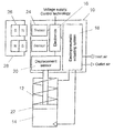
- FIGURE shows a schematic illustration of a valve drive system according to the invention.
- the FIGURE illustrates a valve drive device 10 for driving a pneumatic actuator 12 having a pneumatic cylinder 14 for a process valve.
- Typical components of such a valve drive device 10 are a central electronics 16 , an electropneumatic actuating system 18 and a displacement sensor 20 that determines the position of a piston 22 movable in the pneumatic cylinder 14 .
- valve drive device but extends to all kinds of valve drive devices requiring control actions on specific occasions.
- valve drive device 10 comprises a magnetic field sensor arrangement 24 having two or more sensors which can register a change in the field strength and/or the field direction of a nearby magnetic field and supply corresponding signals.
- Sensors that are suitable for this purpose include, e.g., Hall sensors.
- the magnetic field sensor arrangement 24 is protected against external (mechanical) influences by a plastic housing, which also accommodates the other components of the valve drive device 10 .
- the plastic material does not significantly impair the sensitivity of the magnetic field sensor arrangement 24 .
- the magnetic field sensor arrangement 24 of the valve drive device 10 is adjusted to a magnet arrangement 26 of a hand-operated apparatus 28 which, together with the valve drive device 10 , constitutes a valve drive system.
- the magnet arrangement 26 is received in a plastic housing of the hand-operated apparatus 28 and includes two or more strong permanent magnets.
- the magnet arrangement 26 and the magnetic field sensor arrangement 24 are adjusted to each other, in particular in view of the magnetic field strength and the sensor sensitivity as well as with regard to the geometric arrangement of the permanent magnets and the sensors. As a result, any influence of interference fields is practically ruled out.
- valve drive system The functioning of the valve drive system will now be explained below.
- control actions can be triggered within the valve drive device 10 .
- the hand-operated apparatus 28 with the magnet arrangement 26 is moved close to the magnetic field sensor arrangement 24 , as shown in the Figure, so that the sensors of the magnetic field sensor arrangement 24 can register the presence of and/or the change in the magnetic fields generated by the permanent magnets of the magnet arrangement 26 (field strength and field direction).
- the magnetic field sensor arrangement 24 Depending on the orientation and/or movement (specifically the direction of movement) of the permanent magnets of the magnet arrangement 26 relative to the sensors of the magnetic field sensor arrangement 24 , the magnetic field sensor arrangement 24 generates a signal characteristic of the respective orientation and/or movement. In this way, it is possible to use the hand-operated apparatus 28 to generate various signals in the valve drive device 10 in a contactless manner, which are assigned to different commands defined in the electronics 16 (coding). The commands constitute triggers for corresponding control actions in the valve drive device 10 .
- the magnet arrangement 26 may also include one or more specially shaped permanent magnets. “Specially shaped” in this connection is intended to mean shapes which differ from the typical linear basic shape of a permanent magnet (bar magnet).
- the number of distinguishable signals or commands generally varies with the number of the magnets and sensors provided and the arrangement thereof.
- solenoids In place of permanent magnets, provision may also be made for one or a plurality of solenoids.
- a solenoid control of the solenoids that allows the energization and/or the current flow direction (and, hence, the polarity of the solenoid(s)) to be varied increases the number of possible command codes.
- a suitable variation of the solenoid control in terms of time allows even larger amounts of data to be sequentially transferred to the valve drive device 10 in a wireless and contactless manner.
Landscapes
- Engineering & Computer Science (AREA)
- General Engineering & Computer Science (AREA)
- Mechanical Engineering (AREA)
- Magnetically Actuated Valves (AREA)
- Indication Of The Valve Opening Or Closing Status (AREA)
Applications Claiming Priority (2)
| Application Number | Priority Date | Filing Date | Title |
|---|---|---|---|
| DE202009012183U DE202009012183U1 (de) | 2009-09-08 | 2009-09-08 | Manuell betätigbares Ansteuermodul |
| DE202009012183.6 | 2009-09-08 |
Publications (2)
| Publication Number | Publication Date |
|---|---|
| US20110057131A1 US20110057131A1 (en) | 2011-03-10 |
| US8622366B2 true US8622366B2 (en) | 2014-01-07 |
Family
ID=41361151
Family Applications (1)
| Application Number | Title | Priority Date | Filing Date |
|---|---|---|---|
| US12/877,151 Active 2031-09-21 US8622366B2 (en) | 2009-09-08 | 2010-09-08 | Manually operable drive module |
Country Status (4)
| Country | Link |
|---|---|
| US (1) | US8622366B2 (de) |
| EP (1) | EP2292958B2 (de) |
| DE (1) | DE202009012183U1 (de) |
| DK (1) | DK2292958T3 (de) |
Cited By (1)
| Publication number | Priority date | Publication date | Assignee | Title |
|---|---|---|---|---|
| US20230104100A1 (en) * | 2021-10-04 | 2023-04-06 | Buerkert Werke Gmbh & Co. Kg | Method for detecting a position of a signal generator in a position measuring system, and position measuring system |
Families Citing this family (7)
| Publication number | Priority date | Publication date | Assignee | Title |
|---|---|---|---|---|
| DE202012002019U1 (de) | 2012-02-27 | 2012-04-03 | Bürkert Werke GmbH | Manuell betätigbares Ansteuermodul |
| EP3287996B1 (de) | 2012-05-25 | 2020-04-22 | Mueller International, LLC | Positionsindikator für ventile |
| DE102012105346A1 (de) * | 2012-06-20 | 2013-12-24 | Krones Ag | Antriebsvorrichtung für ein Ventil einer Getränkeabfüllanlage |
| DE102013008033A1 (de) * | 2013-05-13 | 2014-11-13 | Sipos Aktorik Gmbh | Stellantrieb |
| DE102018200219B4 (de) | 2018-01-09 | 2020-10-08 | Festo Se & Co. Kg | Vorrichtung zur Erfassung der Stellung eines Ventilglieds, Ventilbaueinheit, Abfüllanlage und Verfahren zur Inbetriebnahme einer Abfüllanlage |
| CN109300718B (zh) * | 2018-09-13 | 2019-10-11 | 广东求精电气有限公司 | 一种开关柜防误闭锁装置 |
| JP6783484B1 (ja) * | 2020-03-09 | 2020-11-11 | 金子産業株式会社 | 電磁弁 |
Citations (29)
| Publication number | Priority date | Publication date | Assignee | Title |
|---|---|---|---|---|
| US2788070A (en) * | 1954-02-11 | 1957-04-09 | United Shoe Machinery Corp | Presses for cutting blanks from sheet material |
| US3589242A (en) * | 1969-08-18 | 1971-06-29 | Caterpillar Tractor Co | Single lever control for hoeing scraper components |
| US4091627A (en) * | 1976-08-14 | 1978-05-30 | Taiheiyo Engineering Inc. | System and equipment for operating self-advancing supports |
| US4156422A (en) * | 1976-06-11 | 1979-05-29 | Messerschmitt-Bolkow-Blohm Gmbh | Apparatus for treating hydrocephaly |
| US4481389A (en) * | 1982-08-02 | 1984-11-06 | Liquid Level Lectronics, Inc. | Magnetic control device |
| US4540400A (en) * | 1983-02-17 | 1985-09-10 | Cordis Corporation | Non-invasively adjustable valve |
| US4541429A (en) * | 1982-05-10 | 1985-09-17 | Prosl Frank R | Implantable magnetically-actuated valve |
| US4559037A (en) * | 1977-12-28 | 1985-12-17 | Siemens Aktiengesellschaft | Device for the pre-programmable infusion of liquids |
| US4595390A (en) * | 1983-07-21 | 1986-06-17 | Salomon Hakim | Magnetically-adjustable cerebrospinal fluid shunt valve |
| US4718454A (en) * | 1985-11-20 | 1988-01-12 | British Gas Plc | Valve operating system |
| US4772257A (en) * | 1983-12-08 | 1988-09-20 | Salomon Hakim | External programmer for magnetically-adjustable cerebrospinal fluid shunt valve |
| US4805404A (en) * | 1986-07-31 | 1989-02-21 | Societe D'exploitation F.F.D.M.-Pneumat | Portable pneumatic machine having embodied control electronics |
| US5261374A (en) * | 1991-06-21 | 1993-11-16 | Robert Bosch Gmbh | Method and apparatus for controlling a solenoid-valve-controlled fuel-metering system |
| US5349993A (en) * | 1992-10-13 | 1994-09-27 | Polster, Lieder, Woodruff & Lucchesi, Lc. | Beverage dispensing apparatus and retrofitting kit |
| US5551953A (en) * | 1994-10-31 | 1996-09-03 | Alza Corporation | Electrotransport system with remote telemetry link |
| US5637083A (en) * | 1996-01-19 | 1997-06-10 | Pudenz-Schulte Medical Research Corporation | Implantable adjustable fluid flow control valve |
| US5643194A (en) * | 1994-06-24 | 1997-07-01 | Sophysa | Subcutaneous valve and device for externally setting it |
| US5864272A (en) * | 1992-12-02 | 1999-01-26 | Valeo Electronique | Switch having at least two stable positions, especially for a motor vehicle |
| FR2812926A1 (fr) | 2000-08-11 | 2002-02-15 | Chuchu Decayeux | Robinet a condamnation anti-fraude |
| US6474360B1 (en) * | 1999-06-15 | 2002-11-05 | Seiko Instruments Inc. | Variable pressure valve apparatus |
| US20030183792A1 (en) * | 2000-06-06 | 2003-10-02 | Tetsuo Muraji | Electromagnetic actuator and valve driver and position or speed sensor comprising it |
| WO2004099657A1 (en) | 2003-05-05 | 2004-11-18 | Kjp Investments Llc | Digitally controlled modular valve system |
| DE202005020753U1 (de) | 2005-03-01 | 2006-07-20 | American Standard Europe B.V.B.A. | Sanitäres Wasserventil mit berührungsloser Umschaltung zwischen zwei Wasserausläufen |
| DE102005011984A1 (de) | 2005-03-14 | 2006-09-21 | American Standard Europe B.V.B.A. | Elektrisch betriebene Standardarmatur mit getrennt angeordneten Funktionseinheiten |
| DE102007030405B3 (de) | 2007-06-29 | 2008-10-09 | Robert Bosch Gmbh | Elektromagnetischer Aktor mit einer Handhilfsbetätigung für ein Ventil |
| US7460013B1 (en) | 2006-08-14 | 2008-12-02 | Charles Agnew Osborne | Remotely actuated flood free zone valve |
| US20090125024A1 (en) * | 2005-07-08 | 2009-05-14 | Stephan Baur | Medical appliance with magnetic adjustment apparatus |
| US7784490B1 (en) * | 2007-02-27 | 2010-08-31 | Robert Foresman | Valve monitoring and controlling system |
| US7994886B2 (en) * | 2007-05-17 | 2011-08-09 | Korry Electronics Co. | Fault tolerant solid state push button control system with built in diagnostic |
Family Cites Families (10)
| Publication number | Priority date | Publication date | Assignee | Title |
|---|---|---|---|---|
| US519727A (en) * | 1894-05-15 | Half to joseph w | ||
| US4131785A (en) * | 1976-02-18 | 1978-12-26 | Electro-Therm, Inc. | Electrically heated liquid tank employing heat pipe heat transfer means |
| GB2187274B (en) * | 1985-12-26 | 1990-05-16 | Furukawa Electric Co Ltd | Heating apparatus |
| US5259895A (en) * | 1988-07-05 | 1993-11-09 | Sharp Bruce R | Method of building double walled storage tanks |
| US5139390A (en) * | 1991-02-04 | 1992-08-18 | Rajewski Robert K | Pump and method for drawing vapor from a storage tank without forcibly drawing the vapor from the tank |
| US5971009A (en) * | 1997-02-10 | 1999-10-26 | Tanksafe Inc. | Dual containment assembly |
| US6318581B1 (en) * | 2000-03-06 | 2001-11-20 | Snyder Industries, Inc. | Discharge outlet for double wall containment tank assembly |
| US6516754B2 (en) * | 2001-02-20 | 2003-02-11 | Thomas Chadwick | Convective heating system for liquid storage tank |
| JP2005035587A (ja) * | 2003-07-18 | 2005-02-10 | Fuji Photo Film Co Ltd | 貯留タンク |
| US7165572B2 (en) * | 2004-03-31 | 2007-01-23 | Enviro Vault Ltd. | Fluid storage tank with spill containment |
-
2009
- 2009-09-08 DE DE202009012183U patent/DE202009012183U1/de not_active Expired - Lifetime
-
2010
- 2010-08-27 DK DK10008949.9T patent/DK2292958T3/da active
- 2010-08-27 EP EP10008949.9A patent/EP2292958B2/de not_active Not-in-force
- 2010-09-08 US US12/877,151 patent/US8622366B2/en active Active
Patent Citations (29)
| Publication number | Priority date | Publication date | Assignee | Title |
|---|---|---|---|---|
| US2788070A (en) * | 1954-02-11 | 1957-04-09 | United Shoe Machinery Corp | Presses for cutting blanks from sheet material |
| US3589242A (en) * | 1969-08-18 | 1971-06-29 | Caterpillar Tractor Co | Single lever control for hoeing scraper components |
| US4156422A (en) * | 1976-06-11 | 1979-05-29 | Messerschmitt-Bolkow-Blohm Gmbh | Apparatus for treating hydrocephaly |
| US4091627A (en) * | 1976-08-14 | 1978-05-30 | Taiheiyo Engineering Inc. | System and equipment for operating self-advancing supports |
| US4559037A (en) * | 1977-12-28 | 1985-12-17 | Siemens Aktiengesellschaft | Device for the pre-programmable infusion of liquids |
| US4541429A (en) * | 1982-05-10 | 1985-09-17 | Prosl Frank R | Implantable magnetically-actuated valve |
| US4481389A (en) * | 1982-08-02 | 1984-11-06 | Liquid Level Lectronics, Inc. | Magnetic control device |
| US4540400A (en) * | 1983-02-17 | 1985-09-10 | Cordis Corporation | Non-invasively adjustable valve |
| US4595390A (en) * | 1983-07-21 | 1986-06-17 | Salomon Hakim | Magnetically-adjustable cerebrospinal fluid shunt valve |
| US4772257A (en) * | 1983-12-08 | 1988-09-20 | Salomon Hakim | External programmer for magnetically-adjustable cerebrospinal fluid shunt valve |
| US4718454A (en) * | 1985-11-20 | 1988-01-12 | British Gas Plc | Valve operating system |
| US4805404A (en) * | 1986-07-31 | 1989-02-21 | Societe D'exploitation F.F.D.M.-Pneumat | Portable pneumatic machine having embodied control electronics |
| US5261374A (en) * | 1991-06-21 | 1993-11-16 | Robert Bosch Gmbh | Method and apparatus for controlling a solenoid-valve-controlled fuel-metering system |
| US5349993A (en) * | 1992-10-13 | 1994-09-27 | Polster, Lieder, Woodruff & Lucchesi, Lc. | Beverage dispensing apparatus and retrofitting kit |
| US5864272A (en) * | 1992-12-02 | 1999-01-26 | Valeo Electronique | Switch having at least two stable positions, especially for a motor vehicle |
| US5643194A (en) * | 1994-06-24 | 1997-07-01 | Sophysa | Subcutaneous valve and device for externally setting it |
| US5551953A (en) * | 1994-10-31 | 1996-09-03 | Alza Corporation | Electrotransport system with remote telemetry link |
| US5637083A (en) * | 1996-01-19 | 1997-06-10 | Pudenz-Schulte Medical Research Corporation | Implantable adjustable fluid flow control valve |
| US6474360B1 (en) * | 1999-06-15 | 2002-11-05 | Seiko Instruments Inc. | Variable pressure valve apparatus |
| US20030183792A1 (en) * | 2000-06-06 | 2003-10-02 | Tetsuo Muraji | Electromagnetic actuator and valve driver and position or speed sensor comprising it |
| FR2812926A1 (fr) | 2000-08-11 | 2002-02-15 | Chuchu Decayeux | Robinet a condamnation anti-fraude |
| WO2004099657A1 (en) | 2003-05-05 | 2004-11-18 | Kjp Investments Llc | Digitally controlled modular valve system |
| DE202005020753U1 (de) | 2005-03-01 | 2006-07-20 | American Standard Europe B.V.B.A. | Sanitäres Wasserventil mit berührungsloser Umschaltung zwischen zwei Wasserausläufen |
| DE102005011984A1 (de) | 2005-03-14 | 2006-09-21 | American Standard Europe B.V.B.A. | Elektrisch betriebene Standardarmatur mit getrennt angeordneten Funktionseinheiten |
| US20090125024A1 (en) * | 2005-07-08 | 2009-05-14 | Stephan Baur | Medical appliance with magnetic adjustment apparatus |
| US7460013B1 (en) | 2006-08-14 | 2008-12-02 | Charles Agnew Osborne | Remotely actuated flood free zone valve |
| US7784490B1 (en) * | 2007-02-27 | 2010-08-31 | Robert Foresman | Valve monitoring and controlling system |
| US7994886B2 (en) * | 2007-05-17 | 2011-08-09 | Korry Electronics Co. | Fault tolerant solid state push button control system with built in diagnostic |
| DE102007030405B3 (de) | 2007-06-29 | 2008-10-09 | Robert Bosch Gmbh | Elektromagnetischer Aktor mit einer Handhilfsbetätigung für ein Ventil |
Non-Patent Citations (3)
| Title |
|---|
| DE 8235959.8, Nov. 24, 1983, Festo-Maschinenfabrik Gottlieb Stoll. * |
| EP Search Report from EP10008949 dated Nov. 27, 2012. |
| German Search Report mailed May 25, 2010. |
Cited By (2)
| Publication number | Priority date | Publication date | Assignee | Title |
|---|---|---|---|---|
| US20230104100A1 (en) * | 2021-10-04 | 2023-04-06 | Buerkert Werke Gmbh & Co. Kg | Method for detecting a position of a signal generator in a position measuring system, and position measuring system |
| US12379229B2 (en) * | 2021-10-04 | 2025-08-05 | Bürkert Werke GmbH & Co. KG | Method for detecting a position of a signal generator in a position measuring system, and position measuring system |
Also Published As
| Publication number | Publication date |
|---|---|
| EP2292958B1 (de) | 2013-05-08 |
| US20110057131A1 (en) | 2011-03-10 |
| EP2292958A3 (de) | 2013-01-09 |
| EP2292958A2 (de) | 2011-03-09 |
| EP2292958B2 (de) | 2021-09-08 |
| DK2292958T3 (da) | 2013-08-12 |
| DE202009012183U1 (de) | 2009-11-26 |
Similar Documents
| Publication | Publication Date | Title |
|---|---|---|
| US8622366B2 (en) | Manually operable drive module | |
| US8813778B2 (en) | Manually actuated control module | |
| US7503342B2 (en) | Proportional directional control valve with a magnetic positioning sensor | |
| US9631918B2 (en) | Sensor device for a pedal, and a method for providing information regarding an operation of a pedal | |
| US9085879B2 (en) | Electronic control switch for water faucets | |
| CN1868123B (zh) | 用于断开危险装置的安全开关 | |
| US10678291B2 (en) | Actuator, in particular, for a motor vehicle | |
| JP6766279B2 (ja) | バルブ用の作動システム | |
| US20180297813A1 (en) | Device for adjusting the position of an elevator system, and elevator system | |
| CN104279205A (zh) | 活塞缸装置、尤其是用于机动车辆中的分离系统的活塞缸装置 | |
| US10982793B2 (en) | Valve control head | |
| US9511744B2 (en) | Remote control device for a motor vehicle, and method for operating such a remote control device | |
| WO2017089202A1 (en) | Mote control for automotive applications | |
| US12263603B2 (en) | Linear, gripping, clamping, rotary or swiveling device, method for operating a device of this type, and unit for evaluating a device of this type | |
| US11359403B2 (en) | Locking bolt | |
| US20100237856A1 (en) | Arrangement for contactlessly measuring a position using a magnetoresistive sensor, and method for operating the arrangement | |
| NL2018876B1 (en) | Rotational Motion Pattern Input for Mechatronic Lock System | |
| JP3805291B2 (ja) | 弁位置検出スイッチ付パイロット形切換弁 | |
| EP3483456A1 (de) | Vorrichtung zur erfassung der position eines kolbens in einem fluiddruckzylinder | |
| CN114554657B (zh) | 电子产品、调节装置及其调节功能的校准方法 | |
| WO2020242411A1 (en) | Electro-pneumatic positioner | |
| WO2014192018A1 (en) | A system for measuring valve stem displacement | |
| JPH0651810U (ja) | 位置検出装置 |
Legal Events
| Date | Code | Title | Description |
|---|---|---|---|
| AS | Assignment |
Owner name: BUERKERT WERKE GMBH, GERMANY Free format text: ASSIGNMENT OF ASSIGNORS INTEREST;ASSIGNORS:BACHMANN, RENE;BRINKMANN, ULRIKE;GROSSE, KERSTEN;REEL/FRAME:025350/0779 Effective date: 20101025 |
|
| AS | Assignment |
Owner name: BUERKERT WERKE GMBH, GERMANY Free format text: CORRECTIVE ASSIGNMENT TO CORRECT THE ASSIGNEE'S ADDRESS PREVIOUSLY RECORDED ON REEL 025350 FRAME 0779. ASSIGNOR(S) HEREBY CONFIRMS THE ASSIGNEE'S CORRECT ADDRESS TO BE CHRISTIAN-BUERKERT-STRASSE 13-17, INGELFINGEN, GERMANY 74653;ASSIGNORS:BACHMANN, RENE;BRINKMANN, ULRIKE;GROSSE, KERSTEN;REEL/FRAME:025780/0502 Effective date: 20101025 |
|
| STCF | Information on status: patent grant |
Free format text: PATENTED CASE |
|
| CC | Certificate of correction | ||
| FEPP | Fee payment procedure |
Free format text: PAYOR NUMBER ASSIGNED (ORIGINAL EVENT CODE: ASPN); ENTITY STATUS OF PATENT OWNER: LARGE ENTITY |
|
| FPAY | Fee payment |
Year of fee payment: 4 |
|
| MAFP | Maintenance fee payment |
Free format text: PAYMENT OF MAINTENANCE FEE, 8TH YEAR, LARGE ENTITY (ORIGINAL EVENT CODE: M1552); ENTITY STATUS OF PATENT OWNER: LARGE ENTITY Year of fee payment: 8 |
|
| MAFP | Maintenance fee payment |
Free format text: PAYMENT OF MAINTENANCE FEE, 12TH YEAR, LARGE ENTITY (ORIGINAL EVENT CODE: M1553); ENTITY STATUS OF PATENT OWNER: LARGE ENTITY Year of fee payment: 12 |