US8648917B2 - Imaging apparatus, image processing apparatus, and image processing method, and program - Google Patents
Imaging apparatus, image processing apparatus, and image processing method, and program Download PDFInfo
- Publication number
- US8648917B2 US8648917B2 US13/273,862 US201113273862A US8648917B2 US 8648917 B2 US8648917 B2 US 8648917B2 US 201113273862 A US201113273862 A US 201113273862A US 8648917 B2 US8648917 B2 US 8648917B2
- Authority
- US
- United States
- Prior art keywords
- correction
- unit
- vibration
- image
- correction process
- Prior art date
- Legal status (The legal status is an assumption and is not a legal conclusion. Google has not performed a legal analysis and makes no representation as to the accuracy of the status listed.)
- Expired - Fee Related, expires
Links
Images


Classifications
-
- H—ELECTRICITY
- H04—ELECTRIC COMMUNICATION TECHNIQUE
- H04N—PICTORIAL COMMUNICATION, e.g. TELEVISION
- H04N13/00—Stereoscopic video systems; Multi-view video systems; Details thereof
- H04N13/20—Image signal generators
- H04N13/204—Image signal generators using stereoscopic image cameras
- H04N13/246—Calibration of cameras
-
- H—ELECTRICITY
- H04—ELECTRIC COMMUNICATION TECHNIQUE
- H04N—PICTORIAL COMMUNICATION, e.g. TELEVISION
- H04N23/00—Cameras or camera modules comprising electronic image sensors; Control thereof
- H04N23/60—Control of cameras or camera modules
- H04N23/68—Control of cameras or camera modules for stable pick-up of the scene, e.g. compensating for camera body vibrations
- H04N23/681—Motion detection
- H04N23/6812—Motion detection based on additional sensors, e.g. acceleration sensors
-
- H—ELECTRICITY
- H04—ELECTRIC COMMUNICATION TECHNIQUE
- H04N—PICTORIAL COMMUNICATION, e.g. TELEVISION
- H04N13/00—Stereoscopic video systems; Multi-view video systems; Details thereof
- H04N13/20—Image signal generators
- H04N13/204—Image signal generators using stereoscopic image cameras
- H04N13/239—Image signal generators using stereoscopic image cameras using two two-dimensional [2D] image sensors having a relative position equal to or related to the interocular distance
-
- H—ELECTRICITY
- H04—ELECTRIC COMMUNICATION TECHNIQUE
- H04N—PICTORIAL COMMUNICATION, e.g. TELEVISION
- H04N23/00—Cameras or camera modules comprising electronic image sensors; Control thereof
- H04N23/60—Control of cameras or camera modules
- H04N23/68—Control of cameras or camera modules for stable pick-up of the scene, e.g. compensating for camera body vibrations
- H04N23/682—Vibration or motion blur correction
- H04N23/683—Vibration or motion blur correction performed by a processor, e.g. controlling the readout of an image memory
-
- H—ELECTRICITY
- H04—ELECTRIC COMMUNICATION TECHNIQUE
- H04N—PICTORIAL COMMUNICATION, e.g. TELEVISION
- H04N23/00—Cameras or camera modules comprising electronic image sensors; Control thereof
- H04N23/80—Camera processing pipelines; Components thereof
- H04N23/81—Camera processing pipelines; Components thereof for suppressing or minimising disturbance in the image signal generation
Definitions
- the present disclosure relates to an imaging apparatus, an image processing apparatus, an image processing method, and a program. More particularly, the disclosure relates to an imaging apparatus, an image processing apparatus, an image processing method, and a program capable of correcting images captured by the imaging apparatus.
- imaging apparatuses such as a still camera, a video camera, a single lens reflex camera, a camera built-in to a mobile device, a camera built-in to a PC are being miniaturized, and their costs and weights are being reduced.
- these miniaturized and light-weight cameras have many design limitations in the optical systems such as lenses. As a result, image degradation caused by, for example, lens aberration and the like may easily occur.
- Lens distortion aberration is a phenomenon that can easily occur as the zoom ratio of the camera increases.
- lens distortion aberration for example, as follows: (a) barrel distortion by which the captured image is circularly outwardly skewed like a barrel, (b) pincushion distortion by which four corners of the image are extracted and stretched like a pincushion, and (c) a mixture of both distortion types, for example, such as lens distortion aberration or mustache distortion.
- Distortion aberration can be prevented by improving precision of the lens design to some extent, but it is difficult to remove it completely.
- cameras having a function of correcting distortion of the captured image by performing geometrical transformation through image processing are being developed.
- vibration component is divided into translation vectors, for example, using two axes in the horizontal and vertical directions (X and Y directions, respectively), and each correction amount is computed.
- hand-vibration further has a rotational vector component in addition to the translation vector in many cases. Therefore, it is difficult to remove this rotational hand-vibration using the translating correction in the X and Y directions.
- a human being can stereoscopically view an object because both eyes are separated at a certain interval, by which the object is viewed from different directions, and spatially offset images are focused on each retina. That is, a stereoscopic feeling is recognized using parallax between both eyes.
- a so-called stereo camera for capturing stereoscopic images using the imaging apparatus that is, a camera having two optical imaging channels is also based on this principle. Two different channels of images are captured as a source of the stereoscopic image.
- the stereo camera generates two-channel images, that is, the left-eye image and the right-eye image and stores them in a memory.
- the left-eye and right-eye images are alternately displayed, for example, on a 3D display.
- a viewer can view a stereoscopic image by wearing shutter type glasses and viewing each image with only a left eye or only a right eye.
- Various techniques other than the shutter type glasses technique can be employed to display 3D images.
- the stereo camera has some requirements in capturing an image to suppress viewer fatigue and realize comfortable vision. Specifically, it is necessary to adjust setting of the parallax or accurately optimize the installation position or direction of two-channel optical imaging systems for the left-eye image and the right-eye image.
- each channel of the two-channel optical imaging system for the left-eye image and the right-eye image of the stereo camera uses an individual lens, separate lens distortion aberration is individually generated. Therefore, in order to remove distortion aberration, it is necessary to individually correct each lens.
- the image correction process for the image captured by a camera includes lens distortion aberration correction, translating hand-vibration correction, and rotational hand-vibration correction. Further, in the case of a stereo camera, correction is further necessary depending on many other purposes, such as parallax correction for the two-channel optical imaging system.
- an imaging apparatus including: a plurality of imaging units; a correction unit that executes a correction process for images captured by a plurality of the imaging units; and a control unit that computes a correction parameter applied to a correction process in the correction unit, wherein the correction unit executes distortion aberration correction and hand-vibration correction for each of the captured images and an image characteristic matching correction process for matching characteristics between a plurality of images captured by a plurality of the imaging units.
- the correction unit may execute a zoom ratio correction process for matching zoom ratios of a plurality of images captured by a plurality of the imaging units as the image characteristic matching correction process.
- the correction unit may execute an optical axis center correction process for matching optical axis centers of a plurality of images captured by a plurality of the imaging units as the image characteristic matching correction process.
- the correction unit may further execute a parallax correction process for adjusting parallax of a plurality of images captured by a plurality of the imaging units.
- control unit may compute a correction parameter applied to the correction process in the correction unit and provide the correction parameter to the correction unit.
- the correction parameter may be a correction vector applied to coordinate transformation of an image in a correction unit.
- the correction unit may include: a distortion aberration correction unit that executes distortion aberration correction for each of the captured images; a rotational hand-vibration correction unit that executes rotational hand-vibration correction for each of the captured images; a translating hand-vibration correction unit that executes translating hand-vibration correction for each of the captured images; a zoom ratio correction unit that matches zoom ratios as characteristics of a plurality of images captured by a plurality of the imaging units; an optical axis center correction unit that matches optical axis centers as characteristics of a plurality of images captured by a plurality of the imaging units; and a parallax correction unit that executes a parallax correction process for adjusting parallax of a plurality of images captured by a plurality of the imaging units.
- control unit may compute a combined correction vector obtained by combining correction vectors applied to a plurality of different correction processes executed by the correction unit and provide the combined correction vector to the correction unit, and the correction unit may collectively execute a plurality of different correction processes through an image transformation process by applying the combined correction vector.
- the control unit may compute a combined correction vector obtained by combining correction vectors applied to each of a distortion aberration correction process, a rotational hand-vibration correction process, a translating hand-vibration correction process, a zoom ratio correction process, an optical axis center correction process, and a parallax correction process, and provide the combined correction vector to the correction unit, and the correction unit may collectively execute the distortion aberration correction process, the rotational hand-vibration correction process, the translating hand-vibration correction process, the zoom ratio correction process, the optical axis center correction process, and the parallax correction process through an image transformation process by applying the combined correction vector.
- the imaging apparatus may have a distortion aberration data storage unit that stores distortion aberration data corresponding to the imaging unit applied to distortion aberration correction, and the control unit may create a distortion aberration correction parameter based on the data obtained from the distortion aberration data storage unit.
- the imaging apparatus may have an optical axis center correction value storage unit that stores optical axis center correction data applied to optical axis center correction for matching optical axis centers as characteristics of a plurality of images captured by a plurality of imaging units, and the control unit may generate an optical axis center correction parameter based on the data obtained from the optical axis center correction value storage unit.
- the imaging apparatus may have a zoom ratio correction value storage unit that stores zoom ratio correction data applied to zoom ratio correction for matching zoom ratios as characteristics of a plurality of images captured by a plurality of imaging units, and the control unit may generate a zoom ratio correction parameter based on data obtained from the zoom ratio correction value storage unit.
- the imaging apparatus may have a parallax data storage unit that stores parallax data applied to parallax correction for adjusting parallax of a plurality of images captured by a plurality of imaging units, and the control unit may generate a parallax correction parameter based on the data obtained from the parallax data storage unit.
- an image processing apparatus including: a correction unit that executes a correction process for images captured by a plurality of imaging units; and a control unit that computes a correction parameter applied to a correction process in the correction unit, wherein the correction unit executes distortion aberration correction and hand-vibration correction for each captured image and executes an image characteristic matching correction process for matching characteristics of a plurality of images captured by a plurality of the imaging units.
- an image processing method executed in an image processing apparatus including: computing a correction parameter applied to a correction process in a correction unit; and executing the correction process for images captured by a plurality of imaging units by applying the correction parameter, wherein the executing of the correction process includes executing distortion aberration correction and hand-vibration correction for each of the captured images, and executing an image characteristic matching correction process for matching characteristics of a plurality of images captured by a plurality of the imaging units.
- a program for executing a image processing in an image processing apparatus including: computing a correction parameter applied to a correction process in a correction unit; and executing the correction process for images captured by a plurality of imaging units by applying the correction parameter, wherein the executing of the correction process includes executing distortion aberration correction and hand-vibration correction for each of the captured images, and executing an image characteristic matching correction process for matching characteristics of a plurality of images captured by a plurality of the imaging units.
- the program of the present disclosure is a program provided, for example, using a storage medium for an information processing apparatus, a computer, or a system capable of executing various programs or codes.
- a process according to the program is realized by executing such a program in a program execution unit in an information processing apparatus, a computer, or a system.
- a system herein refers to a logical aggregate configuration of a plurality of devices, and it is not necessary to house each device in the same casing.
- the embodiments of the disclosure it is possible to provide a configuration capable of effectively and reliably realizing a plurality of different image correction processes for captured images. Specifically, it is possible to provide a configuration capable of reliably executing zoom ratio correction, distortion aberration correction, rotational hand-vibration correction, translating hand-vibration correction, optical axis center correction, and parallax correction. In addition, it is possible to provide a configuration capable of realizing effective processing by collectively executing such correction processes. Particularly, for zoom ratio correction, optical axis center correction, and parallax correction necessary in a stereo camera that captures two types of images at two different viewpoints, it is possible to provide a high quality 3D image by correcting at least one of the captured images from two imaging units. Furthermore, by computing a combined correction vector by combining the correction vectors applied to each correction process and applying the combined correction vector to the correction, it is possible to realize effective and reliable correction.
- FIGS. 1A and 1B are diagrams illustrating a configuration example of an imaging apparatus according to a first embodiment of the disclosure.
- FIGS. 2A and 2B are diagrams illustrating a configuration example of an imaging apparatus according to a second embodiment of the disclosure.
- FIGS. 3A and 3B are diagrams illustrating a configuration example of an imaging apparatus according to a third embodiment of the disclosure.
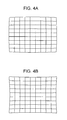
- FIGS. 4A and 4B are diagrams illustrating distortion aberration.
- FIG. 5 is a diagram illustrating a configuration and an installation example of a hand-vibration sensor.
- FIG. 6 is a diagram illustrating a relationship between the zoom position and the gain value of the hand-vibration sensor.
- FIGS. 7A and 7B are diagrams illustrating a distortion aberration correction vector and a translating hand-vibration correction vector.
- FIGS. 8A to 8E are diagrams illustrating a rotational hand-vibration correction vector.
- FIGS. 9A and 9B are diagram illustrating a parallax correction vector.
- FIG. 10 is a diagram illustrating an exemplary setting of addition vectors for distortion aberration correction and rotational hand-vibration correction.
- FIG. 11 is a diagram illustrating a correction example of distortion aberration correction and rotational hand-vibration correction.
- FIG. 12 is a flowchart illustrating a sequence of the image correction process executed by the image processing apparatus according to an embodiment of the disclosure.
- FIG. 13 is a flowchart illustrating a sequence of the image correction process executed by the image processing apparatus according to an embodiment of the disclosure.
- FIG. 14 is a diagram illustrating an exemplary process for setting and obtaining correction data depending on the zoom or focus lens position.
- FIG. 15 is a diagram illustrating an exemplary correction vector as a zoom ratio correction parameter applied to the zoom ratio correction process.
- FIG. 16 is a diagram illustrating an exemplary process for generating an interpolation vector and an exemplary setting of the representative points.
- FIG. 17 is a diagram illustrating a correction vector as an optical axis center correction parameter applied to the optical axis center correction process.
- FIG. 18 is a diagram illustrating an exemplary processing when the correction process is executed by applying the correction vector using each correction unit.
- FIG. 19 is a diagram illustrating an exemplary addition processing example of the correction vector.
- FIGS. 20A to 20C are diagrams illustrating an addition processing example of the correction vector.
- the imaging apparatus according to the disclosure performs image correction for removing image quality degradation generated by various reasons such as lens distortion aberration generated in an optical imaging system, or hand-vibration in a device caused by an operator or an operational condition, for example, including translating hand-vibration or rotational hand-vibration.
- an apparatus having a plurality of imaging systems such as a stereo camera, distortion aberration correction, translating hand-vibration correction, rotational hand-vibration correction, parallax correction for adjusting positional relationship of each output image, and the like are optimally performed by each imaging system.
- each imaging system such as a stereo camera, distortion aberration correction, translating hand-vibration correction, rotational hand-vibration correction, parallax correction for adjusting positional relationship of each output image, and the like are optimally performed by each imaging system.
- distortion aberration correction e.g., a distortion aberration correction, translating hand-vibration correction, rotational hand-vibration correction, parallax correction for adjusting positional relationship of each output image, and the like.
- the image correction processes such as distortion aberration correction, translating hand-vibration correction, rotational hand-vibration correction, and parallax correction executed as a correction process for an image can be realized by geometrical transformation or coordinate transformation of the image. Therefore, a plurality of types of correction can be simultaneously processed by adding correction components to be executed, for example, depending on each purpose and performing image correction, and it is possible to realize effective correction.
- the embodiments include an embodiment in which each correction process such as distortion aberration correction, translating hand-vibration correction, rotational hand-vibration correction, and parallax correction is individually executed, and an embodiment in which those correction processes are collectively executed.
- each correction process such as distortion aberration correction, translating hand-vibration correction, rotational hand-vibration correction, and parallax correction is individually executed, and an embodiment in which those correction processes are collectively executed.
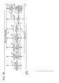
- FIGS. 1A and 1B are configuration diagrams illustrating an embodiment of the imaging apparatus of the present disclosure.
- the imaging apparatus shown in FIGS. 1A and 1B is a stereo camera having a two-channel imaging unit for capturing left-eye and right-eye images, that is, the first imaging unit 111 , and a second imaging unit 121 of FIG. 1A .
- the first imaging unit 111 includes an image sensor 113 such as CCD or CMOS for imaging output light of the lens group 112 , a lens drive unit 114 for driving a predetermined lens in the lens group 112 to read a position thereof, a distortion aberration data storage unit 115 that stores distortion aberration data of the lens group 112 , and a hand-vibration sensor 116 installed in the vicinity of the optical imaging unit to detect vibration thereof.
- an image sensor 113 such as CCD or CMOS for imaging output light of the lens group 112
- a lens drive unit 114 for driving a predetermined lens in the lens group 112 to read a position thereof
- a distortion aberration data storage unit 115 that stores distortion aberration data of the lens group 112
- a hand-vibration sensor 116 installed in the vicinity of the optical imaging unit to detect vibration thereof.
- the second imaging unit 121 also has a configuration similar to that of the first imaging unit 111 , and includes a lens group 122 , an image sensor 123 , a lens drive unit 124 , a distortion aberration data storage unit 125 , and a hand-vibration sensor 126 .
- the distortion aberration data stored in the distortion aberration data storage units 115 and 125 represent distortion aberration types corresponding to the lens groups 112 and 122 of each imaging unit.
- the distortion aberration data has unique values of the lens groups and changes by a zoom position and the like. Therefore, each of the distortion aberration data storage unit 115 and the distortion aberration data storage unit 125 stores discrete distortion aberration data corresponding to several representative zoom positions extending from a wideview end to a teleview end allowed as zoom ranges of the lens groups 112 and 122 of each imaging unit. In addition to a plurality of zoom positions, distortion aberration data corresponding to the focus positions may be stored.
- position information on the zoom lens or the focus lens may be transmitted from the lens drive unit 114 or 124 to the control unit 172 .
- the distortion aberration data depending on the lens position may be read from the distortion aberration data storage unit 115 or 125 and provided to the control unit 172 .
- the control unit 172 computes a distortion aberration correction value for correcting the distortion aberration in the captured image based on such input values and outputs them as parameters for the distortion aberration correction executed by the distortion aberration correction unit 153 .
- the hand-vibration sensors 116 and 126 of each imaging unit 111 and 121 are installed in the vicinity of the imaging unit and output an electric signal depending on a hand-vibration type including a vibration amount or a vibration direction as hand-vibration data to the control unit 172 .
- the control unit 172 adjusts the hand-vibration data input from the hand-vibration sensor 116 and 126 based on the position of the zoom lens or the focus lens obtained from the lens drive unit 114 and 124 , computes a rotational hand-vibration correction value or a translating hand-vibration correction value, and outputs these values as correction parameters to the rotational hand-vibration correction unit 154 for executing rotational hand-vibration correction or the translating hand-vibration correction unit 155 for executing translating hand-vibration correction.
- two imaging units that is, the first imaging unit 111 and the second imaging unit 121 are used as a right camera for capturing a right-eye image and a left camera for capturing a left-eye image, respectively, used for 3D image display.
- the imaging units 111 and 121 read the output signals from the image sensors 113 and 123 , respectively, and the output signals are output to a set of camera signal processing units 151 while they are switched at regular time intervals using the switched multiplexing unit 141 so as to be transformed to a predetermined format of image signals.
- correction processes are sequentially executed using the zoom ratio correction unit 152 to the parallax correction unit 157 in the drawing.
- a part of parameters for the correction processes executed by the zoom ratio correction unit 152 to the parallax correction unit 157 are computed by the control unit 172 .
- the control unit 172 receives the following data from each imaging unit 111 and 121 : the zoom/focus position information from the lens drive units 114 and 124 ; the distortion aberration data from the distortion aberration data storage units 115 and 125 ; the hand-vibration data from the hand-vibration sensors 116 and 126 ; the parallax data from the optical system parallax data storage unit 131 ; the zoom ratio correction data from the zoom ratio correction value storage unit 132 ; and the optical axis center correction data from the optical axis center correction value storage unit 133 ; and computes parameters used to execute correction in the zoom ratio correction unit 152 to the parallax correction unit 157 .
- the computed parameters are provided to the zoom ratio correction unit 152 to the parallax correction unit 157 for executing correction.
- the zoom ratio correction unit 152 to the parallax correction unit 157 execute each image correction process by applying the correction parameters received from the control unit 172 .
- the corrected images obtained through execution in each of the zoom ratio correction unit 152 to the parallax correction unit 157 are stored in the image data storage unit 171 temporarily, and each correction unit extracts the correction result of the correction unit of the previous stage from image data storage unit 171 and executes correction.
- the zoom ratio correction unit 152 to the parallax correction unit 157 execute correction processes by alternately switching the image captured by the first imaging unit 111 and the image captured by the second imaging unit 121 at regular time intervals. That is, the switched multiplexing unit 141 outputs the image captured by the first imaging unit 111 and the image captured by the second imaging unit 121 by alternately switching them at regular time intervals.
- the control unit 172 computes the parameters applied for correction of each image, for example, correction vectors in response to a switching timing and provides the parameters to the zoom ratio correction unit 152 to the parallax correction unit 157 .
- the zoom ratio correction unit 152 executes correction such as zoom in/out of the image depending on the zoom ratio used at the time of imaging.
- the correction process includes a process for matching the zoom ratios of a plurality of images including a pair of the image captured by the first imaging unit 111 and the image captured by the second imaging unit 121 , that is, an image characteristic matching process for matching characteristics of a plurality of images.
- the control unit 172 obtains zoom ratio correction data from the zoom ratio correction value storage unit 132 based on the zoom ratio information input from the lens drive units 114 and 124 and provides them as correction parameters to the zoom ratio correction unit 152 .
- the zoom ratio correction unit 152 executes correction by applying the input parameters.
- a slight difference may occur in the position of the zoom lens or the optical zoom ratio between each imaging unit even when the image is captured set at the zoom position where a user is located, such that a plurality of resulting images may differ slightly.
- a 3D image stereo image
- the zoom ratio correction value storage unit 132 maintains the correction values for remarkably reducing such a difference of the zoom ratio.
- the control unit 172 reads the correction value depending on the condition of the zoom lens or the focus lens from the zoom ratio correction value storage unit 132 , computes a zoom ratio correction parameter based on this read value, and provides it to the zoom ratio correction unit 152 .
- the zoom ratio correction unit 152 executes a zoom in/out process for the image depending on the zoom ratio correction parameter to create a zoom ratio correction image depending on the zoom ratio set at the time of imaging.
- the zoom ratio correction unit 152 processes a single image or each of the images captured by a plurality of imaging units and adjusts the zoom ratios between one another (matching).
- the distortion aberration correction unit 153 executes correction of the lens distortion aberration generated in the captured image.
- the parameters applied to the correction process are computed by the control unit 172 .
- the control unit 172 reads necessary distortion aberration data from the distortion aberration data storage units 115 and 125 depending on the zoom lens position information obtained from the lens drive units 114 and 124 and computes the distortion aberration correction parameter.
- the computed parameter is provided to the distortion aberration correction unit 153 , and the distortion aberration correction unit 153 executes correction by applying the input parameter.
- the coordinates of each pixel are transformed to the coordinates capable of forming an image without distortion aberration so that it is possible to obtain an image signal with fidelity based on the shape of an object.
- the rotational hand-vibration correction unit 154 corrects rotational hand-vibration for the image signal for which the distortion aberration has been corrected. Further, the translating hand-vibration correction unit 155 corrects hand-vibration of an up/down/left/right translating movement to stabilize the image.
- the control unit 172 computes the parameter applied to the hand-vibration correction and provides the parameter to the rotational hand-vibration correction unit 154 and the translating hand-vibration correction unit 155 .
- the control unit 172 reads the rotational hand-vibration data or the translating hand-vibration data from the hand-vibration sensors 116 and 126 and inputs the zoom position/focus position obtained from the lens drive units 114 and 124 .
- the control unit 172 computes the correction parameters applied to the rotational hand-vibration correction and the translating hand-vibration correction based on such an input value.
- the zoom position/focus position obtained from the lens drive units 114 and 124 or the rotational hand-vibration data/translating hand-vibration data obtained from the hand-vibration sensors 116 and 126 are switchingly read in conjunction with the switched multiplexing in the first imaging unit 111 and the second imaging unit 121 .
- the optical axis center correction unit 156 executes correction of the optical axis center for a pair of output images obtained from two imaging units 111 and 121 .
- a pair of output images obtained from two imaging units 111 and 121 can be viewed by a user as a stereoscopic image (3D image) by executing a 3D image display process such as alternate switching display using the image display unit 159 .
- a slight difference is present in the image depending on the installation position of the optical imaging systems of the first and second imaging units 111 and 121 , so that the optical axis center may differ.
- the optical axis center correction unit 156 executes correction of the optical axis center for a pair of output images obtained from a pair of imaging units 111 and 121 such that an optimal positional relationship can be provided. Specifically, the optical axis center correction unit 156 executes a process of matching a plurality of images including a pair of images captured by the first imaging unit 111 the image captured by the second imaging unit 121 , that is, an image characteristic matching correction process.
- the control unit 172 obtains the optical axis center correction data from the optical axis center correction storage unit 133 and provides it to the optical axis center correction unit 156 .
- the optical axis center correction unit 156 executes correction based on the correction value.
- the center of the optical axis passing through the lens unit is slightly deviated on the image sensor depending on installation (assembling) accuracy of the image sensor and the lens unit so as not to match the obtained image center.
- the optical center coordinates of a plurality of obtained images may not match each other. Since such an optical axis center serves as a reference in the distortion aberration of the optical zoom or lens, it is necessary to execute a process of matching them, that is, an optical axis center correction process as a process of matching the optical center coordinates between the image captured by the imaging unit 111 and the image captured by the imaging unit 121 .
- the optical axis center correction value storage unit 133 stores the correction value as the optical axis center correction data for the correction.
- the control unit 172 reads the correction value from the optical axis center correction value storage unit 133 , and computes the correction parameter provided to the optical axis center correction unit 156 , for example, a correction vector for matching the centers of the images captured by a pair of imaging units.
- the optical axis center correction unit 156 performs the process for a single image or for each of the images captured by a plurality of imaging units and performs the correction process for matching the coordinates of the optical axis centers with each other.
- the parallax correction unit 158 performs parallax correction for a pair of output images obtained from two imaging units 111 and 121 .
- the parallax correction unit 158 performs parallax correction based on the parallax correction parameter computed by the control unit 172 . It is possible to know what a distance of a main object from the imaging apparatus is when using the focus position or the zoom position obtained from the lens drive units 114 and 124 .
- the control unit 172 computes this distance, reads the parallax data from the optical system parallax data storage unit 131 depending on a separation interval of two imaging units 111 and 121 , computes the parallax correction parameter, and provides it to the parallax correction unit 158 .
- the parallax correction unit 158 executes parallax correction for correction a parallax distortion using this parameter.
- a parallax distortion correction process executed by the parallax correction unit 158 for example, a process disclosed in Japanese Unexamined Patent Application Publication No. 2008-524673 may be applicable.
- a 3D image (stereoscopic image) obtained as a result is displayed on the image display unit 159 .
- a compression process is performed by the data compression unit 158 to reduce a size, and the resulting 3D image is output to the image storage medium/input-output terminal 160 so that a storing process for a storage unit or an external output process is undertaken.
- each correction processing unit transmits/receives the control data or the setting parameters to/from the control unit 172 .
- each correction unit obtains the correction target image from the image data storage unit 171 and stores the correction result.
- each correction processing unit may directly transmit/receive the image data or may transmit/receive the image data via the image data storage unit 171 .
- the imaging apparatus of FIGS. 2A and 2B illustrates the imaging apparatus according to a second embodiment of the disclosure.
- the imaging apparatus of FIGS. 2A and 2B includes each of two imaging units individually has the correction processing unit followed by the camera signal processing unit.
- the correction processes are executed by the camera signal processing unit 151 , the zoom ratio correction unit 152 , the distortion aberration correction unit 153 , the rotational hand-vibration correction unit 154 , the translating hand-vibration correction unit 155 , the optical axis center correction unit 156 , and the parallax correction unit 157 .
- the correction processes are executed by the camera signal processing unit 201 , the zoom ratio correction unit 202 , the distortion aberration correction unit 203 , the rotational hand-vibration correction unit 204 , the translating hand-vibration correction unit 205 , the optical axis center correction unit 206 , and the parallax correction unit 207 .
- double processing channels are provided for each imaging unit.
- the distortion aberration data, rotational hand-vibration data, translating hand-vibration data, and the like are obtained in each imaging unit as individual data, and they are input to the control unit 172 so that the correction parameters corresponding each imaging unit are computed and provided to each correction unit of each processing channel.
- the correction parameters corresponding each imaging unit are computed and provided to each correction unit of each processing channel.
- the image data storage unit for storing the image in the course of correction and as also shown in the diagram the image data storage unit 171 corresponding to the output of the first imaging unit 111 and the image data storage unit 211 corresponding to the output of the second imaging unit 121 have a configuration so as to be individually set.
- FIGS. 3A and 3B illustrate the imaging apparatus according to the third embodiment of the disclosure.
- the zoom ratio correction unit 152 the distortion aberration correction unit 153 , the rotational hand-vibration correction unit 154 , the translating hand-vibration correction unit 155 , the optical axis center correction unit 156 , and the parallax correction unit 157 of FIG. 1B are substituted into a single image transformation correction unit 251 .
- the correction processes executed in the zoom ratio correction unit 152 , the distortion aberration correction unit 153 , the rotational hand-vibration correction unit 154 , the translating hand-vibration correction unit 155 , the optical axis center correction unit 156 , and the parallax correction unit 157 of FIG. 1B are collectively processed in the image transformation correction unit 251 . Since each correction executed by each correction unit of FIGS. 1A and 1B are a sort of coordinate transformation process, they can be simultaneously processed by combining two or more, or all of them. Through such simultaneous processing, devices can be simplified, and low cost and low power consumption can be obtained. In addition, by integrating a plurality of such correction units, communication of image data to/from the image data storage unit can be remarkably simplified, so that they can be processed at increased speed with low power consumption.
- the hand-vibration sensors 116 and 126 , and the distortion aberration data storage units 115 and 125 are individually provided in each of the first and second imaging units 111 and 121 . Similar to the configuration of FIGS. 1A and 1B , the destination is switched in synchronization with the switched multiplexing of the image signal. On the contrary, since two imaging units are present in the same imaging apparatus, the value of the hand-vibration and the characteristics of the lens distortion aberration can be regarded as the same, and the hand-vibration sensor and the distortion aberration data storage unit can be simplified as a common configuration unit in each imaging unit without individually setting them. That is, only a single hand-vibration sensor and only a single distortion aberration data storage unit can be set, and information can be shared by a plurality of imaging units.
- FIGS. 4A and 4B illustrate images having lens distortion aberration.
- FIG. 4A illustrates barrel distortion by which an image is outwardly skewed in a circular shape
- FIG. 4B illustrates pincushion distortion by which four corners of the image is outwardly extracted and stretched to generate a skew.
- there is a mixture of both types for example, mustache distortion.
- the distortion aberration correction unit or the image transformation correction unit of the image processing apparatus of the disclosure described with reference to FIGS. 1 to 3 is capable of easily performing correction for any one of (a) barrel distortion, (b) pincushion distortion, or a mixture of both types, depending on the values of the distortion aberration data (parameters) stored in advance in the distortion aberration data storage unit.
- FIG. 5 is a diagram illustrating an installation example of the hand-vibration sensor.
- a detection device for hand-vibration there are a mechanical detection device such as a gyro-sensor, and a detection device that detects a motion vector through image processing in a plurality of images. According to the disclosure, any device may be employed as the hand-vibration sensor.
- Examples of the mechanical detection device such as a gyro-sensor include a gyro-sensor that detects a rotation speed in a pillar shape as shown in FIG. 5 .
- the mechanical detection device such as a gyro-sensor
- each hand-vibration sensor is installed very closely to the imaging unit so as to obtain accurate values.
- each hand-vibration sensor may be installed in an optimal position for each imaging unit, or a single hand-vibration sensor may be installed in a suitable position for sharing between both imaging units. Either of configurations may be used.
- FIG. 6 illustrates an adjustment gain of the hand-vibration sensor value depending on the position of the zoom lens.
- the hand-vibration detection device is a mechanical detection device such as a gyro-sensor
- the hand-vibration correction unit is an electronic type (in which the image signal is shifted and cut out)
- the up/down/left/right correction amounts for the image increases as the zoom lens position approaches the teleview even with the same hand-vibration sensor value. Therefore, a look-up table for the adjustment gain thereof is necessary. Reference of this look-up table or adjustment of the hand-vibration value is performed in the control unit.
- the hand-vibration correction process is disclosed in, for example, Japanese Patent Registration No. 3279342.
- the hand-vibration detection device there is a motion vector detection device.
- a motion vector detection device In this technique, a plurality of images captured and obtained at a constant time interval are stored, and a motion vector is extracted through image processing from a plurality of these images. Through this process, it is possible to obtain rotation motion vector as well as translating motion vector.
- a processing configuration is disclosed in, for example, Japanese Patent Registration Nos. 4212109 (assigned by Panasonic Corp.) and 4487811 (assigned by SONY Corp.).
- FIG. 7A illustrates an exemplary setting of the correction vector for the image suffering from barrel distortion aberration.
- the vectors (arrows) illustrated in the image are correction vectors. If barrel distortion aberration is generated when an image of a grid-shaped object perpendicularly extending across the length and the breadth is captured, the straight lines extending across the length and the breadth in the captured image are outwardly inflated and skewed like a barrel. Vectors for correcting this phenomenon are set such that the image is magnified toward the lens periphery depending on a distance from the lens center (in the vicinity of the image center) as shown in FIG. 7A . Typically, the farther from the lens center, the larger the magnitude of the correction vector is toward the lens circumference.
- FIG. 7B is a diagram illustrating an exemplary setting of the correction vectors for the image suffering from the translating hand-vibration.
- the vectors (arrows) in the image are correction vectors.
- the example of FIG. 7B illustrates an exemplary setting of the correction vectors for the image, in which the translating hand-vibration is generated due to a movement from the upper right to the lower left while the image is captured.
- an image sensor uses a necessary image near the center, cut out from a slightly larger image.
- the vibration can be cancelled out by shifting the entire image obtained by the image sensor as much as the vibration amount and cutting out a necessary image. That is, in such a process, the entire image is uniformly corrected using vectors having the same magnitude and the same direction.
- the translating hand-vibration may be corrected by obtaining values from the X-axis vibration sensor and the Y-axis vibration sensor that have been described with reference to FIG. 5 , computing correction values are computed, shifting the position as much as those values. In some cases, since the cutout position may be shifted during the image sensor reading, the entire image is read from the image sensor, a certain process is performed, and then, a write address used to store the image data in the image data storage unit or a read address may be shifted.
- FIGS. 8A to 8E are diagrams illustrating an exemplary setting of the correction vectors for the image suffering from rotational hand-vibration.
- the vectors (arrows) shown in each image are correction vectors. All of the captured images in FIGS. 8A to 8E suffer from counterclockwise rotational hand-vibration in the imaging apparatus side.
- the center of the rotation correction may not necessarily be the center of actual rotational vibration. Since the center of the rotation correction is virtually set when the correction vectors are set, it may be provided basically in any place in the image.
- the center of the rotation correction is preferably not significantly separated from the image in order to maintain accuracy of the setting value of the correction vector. However, it may be set arbitrarily in either the inner side or the outer side of the image.
- the center of the rotation correction is provided in the vicinity of the lower right corner of the image (either the inner or outer side of the image). Therefore, the correction vector is set to a counterclockwise rotation with respect to that point. In addition, the magnitude of the correction vector increases as a distance from the center of the rotation correction increases.
- the centers of the rotational correction are located in the lower left of the image in FIG. 8B , in the upper right of the image in FIG. 8C , in the upper left of the image in FIG. 8D , and in the approximate center of the image in FIG. 8E .
- the setting of the magnitude and the direction of the correction vector is changed depending to the setting of the center position of the rotation correction even in the input image having the same rotational hand-vibration.
- FIGS. 9A and 9B are diagrams illustrating an example of parallax correction.
- FIG. 9A illustrates an image captured by the first imaging unit and,
- FIG. 9B illustrates an image captured by the second imaging unit.
- the vectors (arrows) shown in the image captured by the first imaging unit in FIG. 9A are parallax correction vectors.
- the input image of the parallax correction unit 157 is an image subject to each correction process in the zoom ratio correction unit 152 to the optical axis center correction unit 156 .
- the image captured by the first imaging unit 111 and the image captured by the second imaging unit 121 are slightly different from each other.
- the parallax correction unit 157 obtains correction data from the optical system parallax data storage unit 131 and performs parallax correction for at least one of the image captured by the first imaging unit 111 and the image captured by the second imaging unit 121 such that a stereoscopic image including both images has desired parallax.
- the parallax correction can be realized by translating the image and performing a magnification/reduction process as necessary. Depending on a distance from the imaging apparatus to each object, any one of a case of adjusting the parallax correction data and a case of using fixed data is applied.
- all of the distortion aberration correction, the translating hand-vibration correction, the rotational hand-vibration correction, and the parallax correction can be processed using a coordinate transformation process.
- the translating hand-vibration correction correction vectors can be uniformly generated across the entire window by virtue of horizontal and vertical translating movements, and an image can also be shifted.
- correction vectors are set depending on the position in the image. Therefore, it is possible to simultaneously perform the correction processes using a single correction unit similar to the image transformation correction unit 251 of FIGS. 3A and 3B as described above by setting a combination of both correction vectors.
- FIG. 10 illustrates an exemplary setting of vectors obtained by combining both of the correction vectors applied to the barrel distortion aberration correction described with reference to FIG. 7A and the correction vectors applied to the rotational correction process in a case where the rotation center exists in the image as shown in FIG. 8E .
- the vectors (arrows) indicated in the image are correction vectors executed by combining the barrel distortion aberration correction and the rotational correction.
- each coordinate in the window if a plurality of vectors are added as the coordinate transformation, the correction values can be combined.
- a plurality of types of correction processes can be simultaneously executed by setting vectors for various correction processes to a single combination of the correction vector and executing a coordinate transformation process by applying a combined correction vector using a single correction unit similar to the image transformation correction unit 251 of FIG. 3B .
- FIG. 10 illustrates a combined processing example for the distortion aberration correction and the rotational hand-vibration correction
- other vectors including the correction vectors of the translating hand-vibration correction, parallax correction, and the like can be combined.
- a plurality of types of correction processes can be simultaneously executed.
- FIG. 11 illustrates images suffering from barrel distortion aberration and rotational hand-vibration before and after the correction.
- images having barrel distortion aberration and rotational hand-vibration are captured, and both images are slightly different as much as the difference in their installation positions.
- Both of the two captured images are circularly inflated like a barrel due to lens distortion aberration as shown in FIG. 9A , and rotational hand-vibration is generated with respect to the axis parallel to the lens optical axis.
- barrel distortion aberration correction and rotational hand-vibration correction they are returned to the grid-shaped object perpendicularly extending across the length and the breadth (or distortion is alleviated). Further, parallax of both eyes is corrected, so that a final output image is obtained in a state that a user can comfortably view the image.
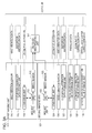
- FIGS. 12 and 13 are flowcharts illustrating a processing sequence of the image correction processes in the imaging apparatus according to the disclosure.
- FIG. 12 illustrates a processing flow corresponding to the device shown in FIGS. 1A and 1B , or 2 A and 2 B. That is, FIG. 12 illustrates a sequence flow of the image correction processes in the device having individual correction units corresponding to each correction purpose.
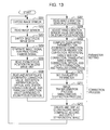
- FIG. 13 illustrates a processing flow corresponding to the device of FIGS. 3A and 3B . That is, FIG. 13 illustrates a sequence flow of the image correction processes in the device having the image transformation correction unit 251 that collectively execute a plurality of correction processes corresponding to a plurality of correction purposes.
- the imaging light is converted into an electric signal and read by the image sensors in step S 102 .
- the imaging light is converted into an electric signal and read by the image sensors in step S 102 .
- the optical zoom ratios may not accurately match each other due to a variation in the lens unit of the imaging unit, or the coordinates of the optical axis center may not match each other due to an installation variation between the lens unit and the image sensor.
- two images input from the image sensors of two imaging units have parallax depending on a distance of the installation position of the imaging unit.
- step S 103 two image signals captured in the two imaging units are output to the camera signal processing unit 151 while they are switched in the switched multiplexing unit 141 at regular time intervals in the configuration of FIGS. 1A and 1B .
- two image signals captured in the two imaging units are individually output to the corresponding camera signal processing units 151 and 201 .
- step S 104 the camera signal processing unit executes a process for converting the image signals into a predetermined format suitable for the correction unit.
- step S 105 the control unit reads the zoom lens position and the focus lens position from the lens drive unit.
- step S 106 the control unit performs a process of reading the data necessary in the correction process depending on such obtained values or computes the correction value applied to computation of the correction parameters in each correction unit. Furthermore, an interpolation process of the correction value, (that is, in a case where it is difficult to directly obtain the correction value from the correction value storage unit, the necessary correction value is computed from a plurality of correction values) and the like are executed as necessary. As the interpolation process, for example, linear interpolation using neighboring correction values and the like may be executed.
- the processing includes: a process of obtaining zoom/focus positions from the lens drive unit and computing the zoom ratio correction value for providing it to the zoom ratio correction unit; a process of reading distortion aberration data corresponding to each lens position during the imaging from the distortion aberration data storage unit, that is, a process of obtaining distortion aberration data for computing parameters applied to the distortion aberration correction process in the distortion aberration correction unit, obtaining optical axis center correction data applied to the correction in the optical axis center correction unit from the optical axis center correction value storage unit, and obtaining parallax data for providing it to the parallax correction unit from the optical system parallax data storage unit; and an interpolation process for computing the correction value if it is difficult to directly obtain the correction value.
- the data applied in each correction process for the correction such as optical zoom ratio correction, lens distortion aberration correction, optical axis center coordinate correction, and parallax correction executed by the apparatus of the disclosure, for example, the following data obtained from each configuration unit of FIGS. 1A and 1B are applied.
- the data includes: zoom/focus position information obtained from the lens drive units 114 and 124 ; distortion aberration data obtained from the distortion aberration data storage units 115 and 125 ; parallax data obtained from the optical system parallax data storage unit 131 ; zoom ratio correction data obtained from the zoom ratio correction value storage unit 132 ; and optical axis center correction data obtained from the optical axis center correction value storage unit 133 .
- the distortion aberration data storage units 115 and 125 , the optical system parallax data storage unit 131 , the zoom ratio correction value storage unit 132 , and the optical axis center correction value storage unit 133 store data corresponding to the positions of various zoom lenses or focus lenses in advance.
- FIG. 14 is a diagram illustrating a state in which such data is discretely stored.
- the zoom lens or the focus lens is actuated end to end of the movable range
- several representative points (posX) to posN) of the lens position are provided, and each correction value is discretely stored at these points.
- the representative points (posX) are set with an equal distances.
- the data as the correction values corresponding to such representative points are discretely stored in the distortion aberration data storage units 115 and 125 , the optical system parallax data storage unit 131 , the zoom ratio correction value storage unit 132 , and the optical axis center correction value storage unit 133 .
- the representative points may be arranged at equal distances or may be densely provided in a range where the data conversion rate is large.
- the correction values are computed through an interpolation process based on the neighboring setup values.
- the interpolation value computation is executed, for example, in the control unit.
- the correction value of the representative point 1 (pos 1 ) and the correction value of the representative point 2 (pos 2 ) can be obtained from the data storage unit.
- the correction values of the representative point 1 (pos 1 ) and the representative point 2 (pos 2 ) are obtained, and based on these correction values, the correction value corresponding a lens position between the representative point 1 (pos 1 ) and the representative point 2 (pos 2 ) is computed through a primary interpolation.
- the correction value may be obtained through higher-order interpolation by increasing the number of points such as the representative point 0 (pos 0 ) and the representative point 3 (pos 3 ).
- the parallax data read from the optical system parallax data storage unit are parallax data corresponding to the object distance.
- the control unit obtains respective lens position information at the time of imaging from the lens drive unit, computes a distance to the main object in the captured image based on the obtained lens position information, and obtains, from the parallax data storage unit, parallax data for adjusting the parallax of both eyes depending on the distance.
- step S 106 the hand-vibration sensor values for three channels including horizontal, vertical, and rotational directions are read from the hand-vibration sensor, and the obtained hand-vibration sensor values are adjusted depending on each lens position based on the relational data between the zoom lens position and the adjustment gain of the hand-vibration sensor value described with reference to FIG. 6 in advance and the like to compute the adjustment value of the hand-vibration sensor value for computing the correction parameters provided to the rotational hand-vibration correction unit and the translating hand-vibration correction unit.
- the control unit reads the adjustment gain value of FIG. 6 from the look-up table that contains such a value in advance in a memory and multiplies it by the value read by the hand-vibration sensor to adjust the input value from the hand-vibration sensor.
- steps S 109 to S 114 is a process of computing the correction parameters applied to the correction process in each correction unit of FIGS. 1 and 2 .
- This parameter computation process is executed by the control unit.
- the data necessary in the parameter computation may be provided from the control unit to each correction unit so that parameters may be computed in each correction unit.
- step S 109 the zoom ratio correction unit computes the zoom ratio correction parameter.
- the zoom ratio correction parameter is set based on the zoom ratio correction value computed by the control unit based on the zoom/focus position information obtained from the lens drive unit.
- step S 110 the distortion aberration correction unit computes the distortion aberration correction parameter.
- the distortion aberration correction parameter is computed based on the distortion aberration data corresponding to each lens position at the time of imaging read from the distortion aberration data storage unit.
- step S 111 the rotational hand-vibration correction unit computes the rotational hand-vibration correction parameter.
- the rotational hand-vibration correction parameter is computed based on the adjustment value of the rotational hand-vibration sensor value read from the hand-vibration sensor in steps S 107 to S 108 , that is, the adjustment value adjusted based on the relational data between the adjustment gain of the hand-vibration sensor and the zoom lens position described with reference to FIG. 6 , and the like.
- the translating hand-vibration correction unit computes the translating hand-vibration correction parameter.
- the translating hand-vibration correction parameter is computed based on the adjustment value of the horizontal and vertical hand-vibration sensor value read from the hand-vibration sensor in step S 107 and S 108 , that is, the adjustment value adjusted based on the relational data between the adjustment gain of the hand-vibration sensor value and the zoom lens position described with reference to FIG. 6 , and the like.
- step S 113 the optical axis center correction unit computes the optical axis center correction parameter.
- the optical axis center correction parameter is computed based on the optical axis center correction data read from the optical axis center correction value storage unit.
- the parallax correction unit computes the parallax correction parameter.
- the parallax correction parameter is computed based on the parallax data read from the optical system parallax data storage unit.
- the parallax data read from the optical system parallax data storage unit is data for adjusting parallax between both eyes depending on the distance to the main object in the captured image and is computed by the control unit based on respective lens position information at the time of imaging.
- the parallax correction parameter is computed based on the parallax data depending on the object distance.
- steps S 115 to S 120 correction processes of each correction unit of FIGS. 1 and 2 are executed.
- step S 115 the zoom ratio correction unit executes the zoom ratio correction process by applying the zoom ratio correction parameter.
- step S 116 the distortion aberration correction unit executes the distortion aberration correction process by applying the distortion aberration correction parameter.
- step S 117 the rotational hand-vibration correction unit executes the rotational hand-vibration correction process by applying the rotational hand-vibration correction parameter.
- step S 118 the translating hand-vibration correction unit executes the translating hand-vibration correction process by applying the translating hand-vibration correction parameter.
- step S 119 the optical axis center correction unit executes the optical axis center correction process by applying the optical axis center correction parameter.
- step S 120 the parallax correction unit executes the parallax correction process by applying the parallax correction parameter.
- each correction process of steps S 116 to S 120 is executed by alternately switching the image captured by the first imaging unit 111 and the image captured by the second imaging unit 121 in the case of the configuration of FIGS. 1A and 1B .
- the correction processes of the image captured by the first imaging unit 111 and the image captured by the second imaging unit 121 are executed in parallel in each correction unit.
- step S 122 a process of displaying 3D images by applying the correction image based on the image captured by the first imaging unit 111 and the correction image based on the image captured by the second imaging unit 121 is executed using the imaging display unit.
- a set of the corrected image data is compressed and recorded in the image storage medium or output from an output terminal to an outer side.
- steps S 201 to S 208 the same processes as those of steps S 101 to S 108 described with reference to FIG. 12 are executed.
- step S 201 exposure is performed using the image sensors of two imaging units.
- step S 202 the imaging light is converted into an electric signal, and read from the image sensor.
- step S 203 the two image signals captured by two imaging units are output to the camera signal processing unit 151 while they are switched by the switched multiplexing unit 141 having the configuration of FIGS. 3A and 3B at regular time intervals.
- step S 204 the camera signal processing unit executes a process of converting the image signal into a predetermined format suitable for the correction unit. Then, in step S 205 , the control unit reads the zoom lens position and the focus lens position from the lens drive unit. Then, in step S 206 , depending on the obtained values, the control unit reads the data necessary in the correction processes or computes the correction values applied to computation of the correction parameters in each correction unit. Furthermore, if necessary, an interpolation process and the like are executed to compute the correction value that is not directly obtained from the correction value data storage unit.
- step S 206 for example, the following process is executed as described above in the process of step S 106 of FIG. 12 .
- the process includes: obtaining the zoom/focus position from the lens drive unit and computing the zoom ratio correction value for providing it to the zoom ratio correction unit; and reading the distortion aberration data corresponding to each lens position at the time of imaging from the distortion aberration data storage unit, that is, including obtaining the distortion aberration data for computing parameters applied to the distortion aberration correction process in the distortion aberration correction unit; obtaining the optical axis center correction data applied to correction in the optical axis center correction unit from the optical axis center correction value storage unit; obtaining parallax data for providing the parallax data to the parallax correction unit from the optical system parallax data storage unit; and an interpolation process for computing the correction value that is not directly obtained.
- the hand-vibration sensor values of the horizontal direction of the three channels, the vertical direction, and the rotational direction are read from the hand-vibration sensor.
- the adjustment values of the hand-vibration sensor values for computing the correction parameters provided to the rotational hand-vibration correction unit and the translating hand-vibration correction unit are computed by adjusting the hand-vibration sensor values obtained depending on each lens position based on the relational data between the zoom lens position and the adjustment gain of the hand-vibration sensor value and the like described above with reference to FIG. 6 .
- steps S 209 and S 210 a process unique to the configuration of FIGS. 3A and 3B is executed.
- the control unit computes the correction parameters corresponding to individual correction purposes and then computes a single correction parameter by combining a plurality of the computed correction parameters.
- control unit computes a combined correction parameter by combining the following correction parameters applied to the correction processes in each correction unit of FIGS. 1 and 2 .
- the correction parameters include:
- the combined correction parameter is computed by combining such correction parameters applied to each correction process.
- a combined correction vector zoom ratio correction vector+distortion aberration correction vector+rotational hand-vibration correction vector+translating hand-vibration correction vector+optical axis center correction vector+parallax correction vector.
- the image transformation correction unit 251 performs the coordinate transformation process using the combined correction vector.
- the combined correction vector as the combined parameter is computed in the unit of each captured image such as the image captured by the first imaging unit 111 and the image captured by the second imaging unit 121 .
- the control unit 172 of FIG. 3B computes the combined correction parameter by combining the correction parameters of the aforementioned parameters (a) to (f) and provides the combined correction parameter to the image transformation correction unit 251 .
- the control unit 172 may compute the combined correction parameter by obtaining or computing the data necessary in the combined parameter computation process and providing this data from the control unit to the image transformation correction unit 251 .
- step S 211 the image transformation correction unit 251 executes the image correction process by applying the combined correction parameter.
- step S 212 the image display unit executes a 3D image display process using the correction image created by the image correction process by applying the combined correction parameter to the image captured by the first imaging unit 111 and the correction image created by the image correction process by applying the combined correction parameter to the image captured by the second imaging unit 121 .
- a set of the corrected image data may be compressed or recorded on an image storage medium or output from an output terminal to the outer side.
- the correction processes executed for the captured images in the apparatus of FIGS. 1 to 3 include:
- any one of such correction processes can be executed as a coordinate transformation process for the captured image.
- a coordinate transformation vector for executing the coordinate transformation process may be used. That is, the coordinate transformation vector is a vector for transforming each pixel position of the image before the correction into the pixel position of the image after the correction.
- the individual vectors include:
- FIG. 15 illustrates exemplary correction vectors as the zoom ratio correction parameter applied to the zoom ratio correction process.
- the vectors (arrows) shown in the image are correction vectors.
- the zoom ratio correction vectors are the same vectors as those shown in FIG. 15 .
- the vectors for moving the pixel positions to match the optical zoom ratios are slightly different between a plurality images obtained from a plurality of imaging units such as the imaging units 111 and 121 of FIG. 1A are used in the zoom ratio correction process.
- the vector setting of FIG. 15 is an exemplary setting of the zoom ratio correction vectors, that is, an exemplary setting of vectors for performing a magnification process through the image processing.
- the correction vectors are set to be directed to the direction opposite to that of FIG. 13 , that is, from the circumference to the center.
- FIG. 15 illustrates only 14 vectors in the image, they are representative vectors corresponding to the representative points set in the image.
- the vectors corresponding to the pixel positions of arbitrary coordinates other than the representative points are computed by an interpolation process using the vectors of the neighboring representative points, and the coordinate transformation is performed based on those vectors. This is similar to other correction processes using the correction vectors described below.
- FIG. 16A illustrates an exemplary grid-shaped representative point arrangement, in which the representative points are regularly arranged across the length and the breadth. In arbitrary coordinates other than the representative points, the vectors are computed through an interpolation process from the vectors of neighboring representative points.
- FIG. 16B illustrates an exemplary arrangement in which the representative points are concentrically arranged with respect to the optical axis considering that the lens distortion aberration varies depending on the image height (a distance from the optical axis center).
- the vectors are small. The further out to the outer side of the image, the larger the magnitude of the vector, and the change rate is apt to increase. Therefore, the representative points are preferably arranged more densely the further to the outer side of the image.
- the vectors are computed through the interpolation process from the neighboring vectors or the distance computation from the optical axis center.
- the correction vectors as the distortion aberration correction parameters applied to the distortion aberration correction process is described above with reference to FIG. 7A .
- the vectors shown in FIG. 7A are an exemplary setting of the correction vectors for the image having barrel distortion aberration.
- the vectors (arrows) shown in the image are correction vectors.
- the straight lines extending across the length and the breaths in the captured image are outwardly circularly inflated and skewed like a barrel.
- the vectors for correction of this phenomenon are set such that the image is enlarged in the lens outer side depending on the distance from the lens center (in the vicinity of the image center) as shown in FIG. 7A . Typically, the farther from the lens center, the more the magnitude of the correction vector increases to the outer side of the lens.
- distortion aberration includes barrel distortion, pincushion distortion, and a mixture of both types (for example, mustache distortion).
- the aspects of such distortion aberration differ depending on the lens configuration of the imaging apparatus or the lens position at the time of imaging.
- the control unit reads optimal distortion aberration data from the distortion aberration data storage unit depending on the lens position at the time of imaging and sets the distortion aberration correction vectors based on the read data.
- the correction vectors as the rotational hand-vibration correction parameter applied to the rotational hand-vibration correction process is described above with reference to FIGS. 8A to 8E .
- All of the examples described with reference to FIGS. 8A to 8E are exemplary settings of the rotational hand-vibration correction vectors in a case where counterclockwise rotational hand-vibration is generated in the imaging apparatus side, and as a result, the image is captured with a counterclockwise inclination.
- the setting of the correction vectors is changed depending on where the rotational correction center is located in the image.
- the rotational correction center may not necessarily be an actual rotational vibration center, and may be virtually provided when the correction vectors are set.
- the rotational correction center may be conveniently set in either an inner or outer side.
- FIGS. 8A to 8E illustrate an exemplary vector setting based on the setting of the rotational correction center in each different position.
- the control unit reads the rotational hand-vibration sensor value from the hand-vibration sensor, adjusts the obtained hand-vibration sensor value depending on each lens position based on the relational data between the adjustment gain of the hand-vibration sensor value and the zoom lens position described above with reference to FIG. 6 , computes the adjustment value of the hand-vibration sensor value, and computes the rotational hand-vibration correction vectors, for example, corresponding to the representative points of FIGS. 8A to 8E based on this computed adjustment value.
- the control unit reads the adjustment gain value of FIG. 6 , for example, from a look-up table stored in a memory in advance, and multiplies the adjustment gain value by the value read from the hand-vibration sensor in order to adjust the input value from the hand-vibration sensor.
- FIG. 7B is a diagram illustrating an exemplary setting for the correction vector for the image having translating hand-vibration.
- Vectors (arrows) in the image are correction vectors.
- FIG. 7B illustrates an exemplary setting of the correction vectors for the image, in which the translating hand-vibration is generated due to a movement from the upper right to the lower left while the image is captured.
- the vibration is canceled out by shifting the entire image obtained by the image sensor as much as the vibration and cutting out the image.
- the translating hand-vibration correction vectors correspond to the vectors for determining the start position thereof. Values indicating each movement amount in the X-axis vibration sensor and the Y-axis vibration sensor described above with reference to FIG. 5 are obtained, and the shift direction and the shift amount are computed based on these values. The setting of the vectors is made based on the computed shift direction and the shift amount.
- FIG. 17 illustrates an exemplary setting of the correction vector as the optical axis center correction parameter applied to the optical axis center correction process.
- the optical axis center correction vector shown in FIG. 17 illustrates an exemplary vector setting in which the entire image is translated and cut out in order to match the coordinates of the optical axis center slightly different between a plurality of images obtained from a plurality of imaging units with each other. Through the coordinate transformation process by applying this vector, it is possible to match the center coordinates between a plurality of images depending on the zoom or focus lens condition.
- FIGS. 9A and 9B illustrate:
- Vectors (arrows) illustrated in the image captured by (a) the first imaging unit are parallax correction vectors.
- the image captured by the first imaging unit 111 and the image captured by the second imaging unit 121 are slightly different due to a different lens installation position.
- the parallax correction unit 157 it is necessary to obtain the correction data from the optical system parallax data storage unit 131 such that the stereoscopic image including both types of images has suitable parallax, and perform the parallax correction for any one of the image captured by the first imaging unit 111 and the image captured by the second imaging unit 121 .
- the vectors applied to the correction process are, for example, the vectors i shown in FIGS. 9A and 9B .
- the parallax correction can be realized by translating the images and performing a magnification/reduction process as necessary. Any one of the case where the parallax correction data is adjusted depending on the distance from the imaging apparatus to each object, or the case where fixed data is used is applied.
- each correction unit computes individual correction vectors depending on each correction purpose as the correction parameter, and sequentially executes the coordinate transformation using the correction vectors in each correction unit.
- FIG. 18 illustrates a processing example in which correction processes are executed by applying the correction vectors corresponding to each correction unit in the device configuration of FIGS. 1A and 1B , or 2 A and 2 B.
- FIG. 18 illustrates an example of the correction vectors and the output images when the following correction processes are sequentially executed using the device configuration of FIGS. 1A and 1B , or 2 A and 2 B.
- a series of images ( 1 a ) ⁇ ( 1 f ) ⁇ ( 1 OUT) illustrate a correction process for the output image of the first imaging unit 111 of FIGS. 1 and 2
- a series of images ( 2 a ) ⁇ ( 2 f ) ⁇ ( 2 OUT) illustrate a correction process for the output image of the second imaging unit 121 of FIGS. 1 and 2 .
- the vectors (arrows) in each image are correction vectors of the representative points applied in each correction process.
- a zoom ratio correction process is executed by applying the zoom ratio correction vector in the zoom ratio correction unit.
- the image ( 1 a ) illustrates the output image of the first imaging unit 111 and the zoom ratio correction vectors for the image.
- the image ( 2 a ) illustrates the output image of the second imaging unit 121 .
- the zoom ratio correction process is the process described above with reference to FIG. 15 and the like, and a process of matching the zoom ratios between two output images.
- the zoom ratio correction process can be performed by executing a magnification or reduction process for any one of the images.
- the image transformation is executed by setting the correction vectors only for the output image of the first imaging unit 111 .
- the results of the zoom ratio correction obtained by applying the vectors in the images become ( 1 b ) and ( 2 b ), respectively, and then, the distortion aberration correction process is executed.
- the images ( 1 b ) and ( 2 b ) of FIG. 18 illustrate the following processes.
- the images ( 2 a ) and ( 2 b ) are similar raw images.
- the distortion aberration correction is the correction, for example, described above with reference to FIG. 7A .
- the correction vectors for the image having the barrel distortion aberration are set such that the image is magnified in the lens outer side depending on the distance from the lens center (in the vicinity of the image center) as shown in FIG. 7A .
- the farther from the lens center the farther from the lens center the more the magnitude of the correction vector increases toward the lens outer side.
- the vectors of the images ( 1 b ) and ( 2 b ) of FIG. 18 have the same setting as that of the vectors of FIG. 7A and illustrate an exemplary correction vectors for the image having the barrel distortion aberration.
- the distortion aberration correction process is executed by applying the vectors in the image.
- the results of the correction become the images ( 1 c ) and ( 2 c ), respectively.
- the curved portion is returned to the straight line, so that a grid-shaped object can be reproduced.
- the images ( 1 c ) and ( 2 c ) of FIG. 18 illustrate the following processes:
- the rotational hand-vibration correction executed by the vectors shown in the images ( 1 c ) and ( 2 c ) of FIG. 18 is the correction, for example, described above with reference to FIGS. 8A to 8E .
- the example of the images ( 1 c ) and ( 2 c ) of FIG. 18 is an exemplary setting of the vectors corresponding to the example in which the rotation center is set to the image center as shown in FIG. 8E .
- the setting of the correction vectors is changed depending on where the rotational correction center is provided in the image.
- the rotational correction center is not necessarily an actual rotational vibration center, and may be virtually provided when the correction vectors are set.
- the vectors are set in predetermined positions.
- a rotational hand-vibration correction process is executed by applying the vectors shown in the images.
- the correction results thereof become the images ( 1 d ) and ( 2 d ).
- the images ( 1 d ) and ( 2 d ) are images obtained by removing the rotational components.
- the following translating hand-vibration correction process is executed.
- the images ( 1 d ) and ( 2 d ) of FIG. 18 illustrate the following processes:
- ( 2 c ) exemplary setting of the translating hand-vibration correction vectors for the correction images obtained by executing the zoom ratio correction, the distortion aberration correction, and the rotational hand-vibration correction process for the output image of the second imaging unit 121 .
- the translating hand-vibration correction executed by the vectors of the images ( 1 d ) and ( 2 d ) of FIG. 18 is the correction, for example, described above with reference to FIG. 7B .
- the example of FIG. 7B illustrates an exemplary setting of the correction vectors for the image, in which the translating hand-vibration is generated due to a movement from the upper right to the lower left while the image is captured.
- the correction vectors shown in the images ( 1 c ) and ( 2 c ) of FIG. 18 are an exemplary setting of the correction vectors for the image, in which a translating hand-vibration is generated due to a movement from the lower right to the upper left while the image is captured unlike the example of FIG. 7B .
- the translating hand-vibration correction process is executed by applying the vectors in the image.
- the correction result becomes the images ( 1 e ) and ( 2 e ), and the translating hand-vibration component is removed, so that a stable image can be obtained in a time-axis direction.
- the following optical axis center correction process is executed.
- the images ( 1 e ) and ( 2 e ) of FIG. 18 illustrate the following processes:
- ( 2 e ) exemplary setting of the optical axis center correction vector for the correction image obtained by executing the zoom ratio correction, the distortion aberration correction, the rotational hand-vibration correction, and the translating hand-vibration correction process for the output image of the second imaging unit 121 .
- the optical axis center correction can be performed just by executing the correction for any one of the images.
- the correction is executed by setting the vectors only for the first image ( 1 e ) of FIG. 18 .
- the optical axis center correction process executed by the vectors of the images ( 1 e ) and ( 2 e ) of FIG. 18 is related to, for example, the correction described above with reference to FIG. 17 .
- the optical axis center correction vector is set as a vector for translating the entire image and cutting out the image to matching the optical axis center coordinates different between a plurality of images obtained from a plurality of imaging units with each other.
- the optical axis center correction process is executed by applying the vectors in the images.
- the correction results become the images ( 1 f ) and ( 2 f ), and the following parallax correction process is executed.
- the images ( 1 f ) and ( 2 f ) of FIG. 18 illustrate the following processes:
- ( 2 f ) exemplary setting of the parallax correction vectors for the correction image obtained by executing the zoom ratio correction, the distortion aberration correction, the rotational hand-vibration correction, the translating hand-vibration correction, and the optical axis center correction process for the output image of the second imaging unit 121 .
- the parallax correction can be performed just by executing the correction for any one of the images.
- the correction is performed by setting the vectors only for the first image ( 1 f ) of FIG. 18 .
- the parallax correction process executed by the vectors shown in the images ( 1 f ) and ( 2 f ) of FIG. 18 is related to, for example, the correction described above with reference to FIGS. 9A and 9B .
- the parallax correction is the correction process for executing adjustment of the parallax such that the stereoscopic image including both types of images has suitable parallax.
- Parallax correction is performed for the image captured by the first imaging unit 111 or the image captured by the second imaging unit 121 based on the vectors.
- the parallax correction can be realized by translating the image.
- the parallax correction may be executed as a process accompanied by the magnification/reduction process.
- the parallax correction is performed by setting the translating vectors only for the first image ( 1 f ) of FIG. 18 .
- the parallax correction process is executed by applying the vectors in the image.
- the correction results become the images ( 1 out) and ( 2 out).
- Such images are output to the display device capable of executing 3D image display, so that the 3D image is displayed.
- the stereoscopic image obtained by performing a correction process for matching one image with the other image or a correction process for approximating both types of images becomes a comfortable image that can be remarkably easily viewed.
- (b) distortion aberration correction, (c) rotational hand-vibration correction, and (d) translating hand-vibration correction are necessary to form a more clear and stable image without vibration with high fidelity even using a monocular camera, and become the correction processes indispensable to display either 2D or 3D images.
- all of the correction processes in each correction unit can be executed through the coordinate transformation process by applying vectors.
- control unit 172 combines the correction vectors applied to each of the correction processes (a) to (f) to compute a single combined correction vector, and the image transformation correction unit 251 executes processes by applying the combined correction vector.
- the process of computing the single combined correction vector by combining the correction vectors applied to each of the aforementioned correction processes (a) to (f) may be executed as a vector addition process.
- An example of the vector addition will be described with reference to FIG. 19 .
- FIG. 19 illustrates a vector addition process applied to two different correction processes as an example of the vector addition.
- the two correction processes are:
- a virtual correction process sequence is reversed to obtain the setting value. For example, it is assumed that the point C shown in FIG. 19 is located in the intersection in the grid where the correction parameters are to be stored.
- the process of computing the combined correction vector may be executed, for example, by obtaining the corresponding point of the input image before the correction assuming that the point C is set to the point obtained after the distortion aberration correction and the rotational hand-vibration correction.
- the coordinate of the point B is transformed to the point C according to (2) rotational hand-vibration correction.
- the coordinate of the point B is transformed to the point A according to (1) distortion aberration correction.
- the coordinate of the point C corresponds to the point A in the input image.
- the rotational hand-vibration correction vector for the point B is different from the rotational hand-vibration correction vector for the point A, it is important to obtain the vector in each stage by reversing the processing sequence.
- the vector as the correction parameter set to the point C becomes the vector directing from the point A to the point C.
- combining the correction vectors is not a simple vector sum, but may be achieved by obtaining the original coordinate in the input image by reversing the sequence of each correction process.
- FIG. 19 illustrates an example of combining two correction vectors, including (1) distortion aberration correction and (2) rotational hand-vibration correction.
- the combined vector can also be computed by reversing the sequence of each correction process to return to original coordinate before the correction.
- the combined vector may be computed for all of the intersections in the grid.
- the control unit obtains the combined correction vector to be set for each representative point by returning to the original coordinate in a reversed sequence from the images ( 1 f ) and ( 2 f ) to the images ( 1 a ) and ( 2 a ) of FIG. 18 considering the sequence of the coordinate transformation in each correction process.
- the computation efficiency can be improved by dividing, the correction vectors to be combined, into horizontal and vertical vectors and then combining them.
- FIGS. 20A to 20C illustrate a configuration example in which the correction processes are processed by dividing into horizontal and vertical sequences.
- the grid is set as shown in FIG. 20A , and the correction vector is set for the points A and C.
- the 2 Z-vectors for transforming coordinates from the points B and D to the points A and C, respectively.
- the point A can be divided into the horizontal vector VHA′ and the vertical vector VVA
- the point C can be divided into the horizontal vector VHC′ and the vertical vector VVC.
- the vector to be set for the grid point A is the original coordinate to be moved to the point A, that is, a relative position at the point B.
- the original coordinate of the point A becomes the point B′, which is not a suitable coordinate transformation. Therefore, FIG. 20B is not used.
- the combined correction vector is processed by sequentially executing the process for obtaining original coordinates before the transformation in each stage.
- a series of processes described herein may be executed by hardware, software, or a combination thereof.
- a program recording the processing sequence may be installed and executed in a memory in a computer integrated into dedicated hardware, or a program may be installed and executed in a general-purpose computer that can execute various processes.
- the program may be stored in a recording medium in advance.
- the program may be received via networks such as the Internet and a local area network (LAN) and installed in a recording medium such as a hard disk inside.
- networks such as the Internet and a local area network (LAN) and installed in a recording medium such as a hard disk inside.
- LAN local area network
- Various processes described herein may be sequentially executed along the description, or may be individually or in parallel executed depending on necessity or a processing capacity of the device which executes processing.
- a system as used herein is a logical aggregate configuration including a plurality of devices, and each device is not necessarily housed in the same casing.
Landscapes
- Engineering & Computer Science (AREA)
- Multimedia (AREA)
- Signal Processing (AREA)
- Studio Devices (AREA)
- Image Processing (AREA)
- Testing, Inspecting, Measuring Of Stereoscopic Televisions And Televisions (AREA)
Abstract
Description
=zoom ratio correction vector+distortion aberration correction vector+rotational hand-vibration correction vector+translating hand-vibration correction vector+optical axis center correction vector+parallax correction vector.
Claims (15)
Applications Claiming Priority (3)
| Application Number | Priority Date | Filing Date | Title |
|---|---|---|---|
| JPP2010-248838 | 2010-11-05 | ||
| JP2010248838A JP5742179B2 (en) | 2010-11-05 | 2010-11-05 | Imaging apparatus, image processing apparatus, image processing method, and program |
| JP2010-248838 | 2010-11-05 |
Publications (2)
| Publication Number | Publication Date |
|---|---|
| US20120113278A1 US20120113278A1 (en) | 2012-05-10 |
| US8648917B2 true US8648917B2 (en) | 2014-02-11 |
Family
ID=46019290
Family Applications (1)
| Application Number | Title | Priority Date | Filing Date |
|---|---|---|---|
| US13/273,862 Expired - Fee Related US8648917B2 (en) | 2010-11-05 | 2011-10-14 | Imaging apparatus, image processing apparatus, and image processing method, and program |
Country Status (3)
| Country | Link |
|---|---|
| US (1) | US8648917B2 (en) |
| JP (1) | JP5742179B2 (en) |
| CN (1) | CN102457752B (en) |
Cited By (1)
| Publication number | Priority date | Publication date | Assignee | Title |
|---|---|---|---|---|
| US20150281507A1 (en) * | 2014-03-25 | 2015-10-01 | 6115187 Canada, d/b/a ImmerVision, Inc. | Automated definition of system behavior or user experience by recording, sharing, and processing information associated with wide-angle image |
Families Citing this family (45)
| Publication number | Priority date | Publication date | Assignee | Title |
|---|---|---|---|---|
| KR20100082147A (en) * | 2009-01-08 | 2010-07-16 | 삼성전자주식회사 | Method for enlarging and changing captured image, and phographed apparatus using the same |
| DE102011109301B4 (en) * | 2011-08-03 | 2013-05-08 | 3Ality Digital Systems, Llc | Method for correcting the zoom setting and / or the vertical offset of partial images of a stereo film as well as controlling or controlling a camera digit with two cameras |
| JP2013123215A (en) * | 2011-11-07 | 2013-06-20 | Panasonic Corp | Imaging apparatus, controller, and computer program |
| JP2013165487A (en) * | 2012-01-11 | 2013-08-22 | Panasonic Corp | Image processing apparatus, image capturing apparatus, and program |
| CN108364623B (en) * | 2012-02-22 | 2021-09-07 | 索尼公司 | Information processing apparatus, information processing method, and computer-readable medium |
| JP5650351B2 (en) * | 2012-03-15 | 2015-01-07 | 富士フイルム株式会社 | Imaging apparatus and electronic viewfinder display method |
| JP5687654B2 (en) * | 2012-03-29 | 2015-03-18 | 株式会社東芝 | Image processing apparatus, stereoscopic image display apparatus, image processing method, and image processing program |
| US9013558B2 (en) * | 2012-07-02 | 2015-04-21 | Sony Corporation | System and method for alignment of stereo views |
| JP6108773B2 (en) * | 2012-11-06 | 2017-04-05 | キヤノン株式会社 | Image processing apparatus, control method thereof, and control program |
| JP6041651B2 (en) * | 2012-12-10 | 2016-12-14 | キヤノン株式会社 | Image processing apparatus, image processing method, and program |
| US20140276104A1 (en) * | 2013-03-14 | 2014-09-18 | Nongjian Tao | System and method for non-contact monitoring of physiological parameters |
| JP2014241473A (en) * | 2013-06-11 | 2014-12-25 | 株式会社東芝 | Image processing device, method, and program, and stereoscopic image display device |
| JP6253280B2 (en) * | 2013-07-04 | 2017-12-27 | キヤノン株式会社 | Imaging apparatus and control method thereof |
| US11019258B2 (en) | 2013-08-21 | 2021-05-25 | Verizon Patent And Licensing Inc. | Aggregating images and audio data to generate content |
| US9451162B2 (en) | 2013-08-21 | 2016-09-20 | Jaunt Inc. | Camera array including camera modules |
| JP6170395B2 (en) * | 2013-09-26 | 2017-07-26 | キヤノン株式会社 | Imaging apparatus and control method thereof |
| TWI594632B (en) * | 2013-12-31 | 2017-08-01 | 佳能企業股份有限公司 | Method for setting image correcting parameters, electronic apparatus, electronic apparatus readable storage medium and program apllied in electronic apparatus |
| US11108971B2 (en) * | 2014-07-25 | 2021-08-31 | Verzon Patent and Licensing Ine. | Camera array removing lens distortion |
| US10440398B2 (en) | 2014-07-28 | 2019-10-08 | Jaunt, Inc. | Probabilistic model to compress images for three-dimensional video |
| KR20160068407A (en) * | 2014-12-05 | 2016-06-15 | 삼성전기주식회사 | Photographing apparatus and control method thereof |
| US9684970B2 (en) * | 2015-02-27 | 2017-06-20 | Qualcomm Incorporated | Fast adaptive estimation of motion blur for coherent rendering |
| US10007998B2 (en) | 2015-03-20 | 2018-06-26 | Ricoh Company, Ltd. | Image processor, apparatus, and control system for correction of stereo images |
| CN107852462B (en) * | 2015-07-22 | 2020-12-18 | 索尼公司 | Camera module, solid-state imaging element, electronic device, and imaging method |
| JP6671994B2 (en) * | 2016-02-02 | 2020-03-25 | キヤノン株式会社 | Imaging device and control method therefor, program, storage medium |
| JP6164564B1 (en) | 2016-03-14 | 2017-07-19 | リアロップ株式会社 | Image processing apparatus, image processing method, recording medium, program, and imaging apparatus |
| CN108885335B (en) | 2016-03-30 | 2021-10-22 | 索尼奥林巴斯医疗解决方案公司 | Medical stereoscopic observation device, medical stereoscopic observation method and procedure |
| JP6214713B1 (en) * | 2016-04-18 | 2017-10-18 | キヤノン株式会社 | Image processing apparatus, imaging apparatus, lens apparatus, image processing method, program, storage medium, and information processing method |
| JP6682336B2 (en) * | 2016-04-20 | 2020-04-15 | オリンパス株式会社 | Camera system and camera body |
| KR102462502B1 (en) * | 2016-08-16 | 2022-11-02 | 삼성전자주식회사 | Automated driving method based on stereo camera and apparatus thereof |
| US11032535B2 (en) | 2016-09-19 | 2021-06-08 | Verizon Patent And Licensing Inc. | Generating a three-dimensional preview of a three-dimensional video |
| US11032536B2 (en) | 2016-09-19 | 2021-06-08 | Verizon Patent And Licensing Inc. | Generating a three-dimensional preview from a two-dimensional selectable icon of a three-dimensional reality video |
| JP6823469B2 (en) | 2017-01-20 | 2021-02-03 | キヤノン株式会社 | Image blur correction device and its control method, image pickup device, program, storage medium |
| DE102018107950B4 (en) | 2017-04-18 | 2025-02-20 | Canon Kabushiki Kaisha | IMAGE PROCESSING DEVICE, IMAGE PROCESSING METHOD AND IMAGE CAPTURE DEVICE |
| JP6734994B2 (en) * | 2017-06-23 | 2020-08-05 | 株式会社日立製作所 | Stereo measuring device and system |
| JP2019062340A (en) * | 2017-09-26 | 2019-04-18 | キヤノン株式会社 | Image blurring correction apparatus and control method |
| EP3557523B1 (en) * | 2018-04-18 | 2021-07-28 | B&R Industrial Automation GmbH | Method for generating a correcting model of a camera for correcting an imaging error |
| EP3618442B1 (en) * | 2018-08-27 | 2020-09-30 | Axis AB | An image capturing device, a method and computer program product for forming an encoded image |
| JP2020098412A (en) * | 2018-12-17 | 2020-06-25 | キヤノン株式会社 | Information processing apparatus, information processing method, and program |
| WO2021085803A1 (en) * | 2019-10-30 | 2021-05-06 | 엘지전자 주식회사 | Mobile terminal |
| JP7580914B2 (en) * | 2019-12-27 | 2024-11-12 | キヤノン株式会社 | Image processing device, image processing method, and program |
| EP4094041A4 (en) * | 2020-01-22 | 2024-07-03 | Photonic Medical Inc. | CALIBRATED, MULTIMODAL, OPEN-VIEW DIGITAL MAGNIFIER WITH DEPTH DETECTION |
| JP7631720B2 (en) * | 2020-09-30 | 2025-02-19 | セイコーエプソン株式会社 | CIRCUIT DEVICE, DISPLAY SYSTEM, AND IMAGE PROCESSING METHOD |
| CN113452920B (en) * | 2021-07-26 | 2022-10-21 | 北京字节跳动网络技术有限公司 | Focus point determining method, device, equipment and medium |
| JP2023105524A (en) * | 2022-01-19 | 2023-07-31 | 株式会社ソニー・インタラクティブエンタテインメント | DISPLAY CONTROL DEVICE, HEAD MOUNTED DISPLAY, AND DISPLAY CONTROL METHOD |
| CN120568201A (en) * | 2024-02-29 | 2025-08-29 | 安霸国际有限合伙企业 | Electronic image stabilization for large zoom ratio lenses |
Citations (5)
| Publication number | Priority date | Publication date | Assignee | Title |
|---|---|---|---|---|
| WO2006062325A1 (en) | 2004-12-06 | 2006-06-15 | Electronics And Telecommunications Research Institute | Apparatus for correcting image distortion of stereo-camera and method thereof |
| JP2008524673A (en) | 2004-12-06 | 2008-07-10 | エレクトロニクス アンド テレコミュニケーションズ リサーチ インスチチュート | Stereo camera image distortion correction apparatus and method |
| US20080291447A1 (en) * | 2007-05-25 | 2008-11-27 | Dudi Vakrat | Optical Chromatic Aberration Correction and Calibration in Digital Cameras |
| US20100295956A1 (en) * | 2009-05-25 | 2010-11-25 | Sony Corporation | Imaging apparatus and shake correcting method |
| US20110141228A1 (en) * | 2009-12-15 | 2011-06-16 | Sony Corporation | Image capturing apparatus and image capturing method |
Family Cites Families (7)
| Publication number | Priority date | Publication date | Assignee | Title |
|---|---|---|---|---|
| JP4328551B2 (en) * | 2003-03-05 | 2009-09-09 | 富士重工業株式会社 | Imaging posture control device |
| JP4418317B2 (en) * | 2004-07-21 | 2010-02-17 | オリンパス株式会社 | Imaging device |
| JP4406711B2 (en) * | 2005-02-16 | 2010-02-03 | ソニー株式会社 | Image data processing method and image data processing apparatus |
| JP4914420B2 (en) * | 2008-10-27 | 2012-04-11 | 富士フイルム株式会社 | Imaging device, compound eye imaging device, and imaging control method |
| JP4852591B2 (en) * | 2008-11-27 | 2012-01-11 | 富士フイルム株式会社 | Stereoscopic image processing apparatus, method, recording medium, and stereoscopic imaging apparatus |
| JP2010204304A (en) * | 2009-03-02 | 2010-09-16 | Panasonic Corp | Image capturing device, operator monitoring device, method for measuring distance to face |
| CN101505433A (en) * | 2009-03-13 | 2009-08-12 | 四川大学 | Real acquisition real display multi-lens digital stereo system |
-
2010
- 2010-11-05 JP JP2010248838A patent/JP5742179B2/en not_active Expired - Fee Related
-
2011
- 2011-10-14 US US13/273,862 patent/US8648917B2/en not_active Expired - Fee Related
- 2011-10-28 CN CN201110339449.7A patent/CN102457752B/en not_active Expired - Fee Related
Patent Citations (5)
| Publication number | Priority date | Publication date | Assignee | Title |
|---|---|---|---|---|
| WO2006062325A1 (en) | 2004-12-06 | 2006-06-15 | Electronics And Telecommunications Research Institute | Apparatus for correcting image distortion of stereo-camera and method thereof |
| JP2008524673A (en) | 2004-12-06 | 2008-07-10 | エレクトロニクス アンド テレコミュニケーションズ リサーチ インスチチュート | Stereo camera image distortion correction apparatus and method |
| US20080291447A1 (en) * | 2007-05-25 | 2008-11-27 | Dudi Vakrat | Optical Chromatic Aberration Correction and Calibration in Digital Cameras |
| US20100295956A1 (en) * | 2009-05-25 | 2010-11-25 | Sony Corporation | Imaging apparatus and shake correcting method |
| US20110141228A1 (en) * | 2009-12-15 | 2011-06-16 | Sony Corporation | Image capturing apparatus and image capturing method |
Cited By (3)
| Publication number | Priority date | Publication date | Assignee | Title |
|---|---|---|---|---|
| US20150281507A1 (en) * | 2014-03-25 | 2015-10-01 | 6115187 Canada, d/b/a ImmerVision, Inc. | Automated definition of system behavior or user experience by recording, sharing, and processing information associated with wide-angle image |
| US10516799B2 (en) * | 2014-03-25 | 2019-12-24 | Immervision, Inc. | Automated definition of system behavior or user experience by recording, sharing, and processing information associated with wide-angle image |
| US10924623B2 (en) | 2014-03-25 | 2021-02-16 | Immervision, Inc. | Automated identification of panoramic imagers for appropriate and efficient panoramic image distortion processing system |
Also Published As
| Publication number | Publication date |
|---|---|
| CN102457752A (en) | 2012-05-16 |
| JP2012103741A (en) | 2012-05-31 |
| CN102457752B (en) | 2016-01-20 |
| JP5742179B2 (en) | 2015-07-01 |
| US20120113278A1 (en) | 2012-05-10 |
Similar Documents
| Publication | Publication Date | Title |
|---|---|---|
| US8648917B2 (en) | Imaging apparatus, image processing apparatus, and image processing method, and program | |
| US8908011B2 (en) | Three-dimensional video creating device and three-dimensional video creating method | |
| EP2532166B1 (en) | Method, apparatus and computer program for selecting a stereoscopic imaging viewpoint pair | |
| US20120200680A1 (en) | Display device and method for providing 3D image of the display device | |
| US9661303B2 (en) | Multi-camera stereoscopic imaging apparatus for reducing the effects of aberration | |
| US20130286170A1 (en) | Method and apparatus for providing mono-vision in multi-view system | |
| CN103444192B (en) | Stereoscopic imaging apparatus and stereoscopic imaging method | |
| WO2013108339A1 (en) | Stereo imaging device | |
| WO2006062325A1 (en) | Apparatus for correcting image distortion of stereo-camera and method thereof | |
| JP4995092B2 (en) | Stereo camera image distortion correction apparatus and method | |
| US20130093855A1 (en) | Parallel axis stereoscopic camera | |
| JP5889022B2 (en) | Imaging apparatus, image processing apparatus, image processing method, and program | |
| CN102893616B (en) | Stereoscopic image capture device | |
| JP2012042912A (en) | Stereoscopic image pickup device and lens driving method in stereoscopic image pickup device | |
| WO2014141653A1 (en) | Image generation device, imaging device, and image generation method | |
| CN103828362B (en) | Imaging device and video recording and reproducing system | |
| US20140015938A1 (en) | Lens system for 3d video taking | |
| JP6732440B2 (en) | Image processing apparatus, image processing method, and program thereof | |
| JP5297899B2 (en) | Stereoscopic image adjustment device, stereoscopic image adjustment system, and program | |
| JP5838775B2 (en) | Image processing method, image processing system, and image processing program | |
| CN102447929A (en) | Display control chip and stereoscopic display equipment | |
| KR101293115B1 (en) | Method for aligning optical axes of stereoscopic camera and the stereoscopic camera, program storing medium for executing the method | |
| JP2013057740A (en) | Stereoscopic video imaging system and lens device | |
| US20250240399A1 (en) | Electronic device and control method of electronic device | |
| US20130050435A1 (en) | Stereo camera system and method for controlling convergence |
Legal Events
| Date | Code | Title | Description |
|---|---|---|---|
| FEPP | Fee payment procedure |
Free format text: PAYOR NUMBER ASSIGNED (ORIGINAL EVENT CODE: ASPN); ENTITY STATUS OF PATENT OWNER: LARGE ENTITY |
|
| AS | Assignment |
Owner name: SONY CORPORATION, JAPAN Free format text: ASSIGNMENT OF ASSIGNORS INTEREST;ASSIGNOR:OKADA, MIYUKI;REEL/FRAME:031874/0625 Effective date: 20131121 |
|
| STCF | Information on status: patent grant |
Free format text: PATENTED CASE |
|
| FPAY | Fee payment |
Year of fee payment: 4 |
|
| MAFP | Maintenance fee payment |
Free format text: PAYMENT OF MAINTENANCE FEE, 8TH YEAR, LARGE ENTITY (ORIGINAL EVENT CODE: M1552); ENTITY STATUS OF PATENT OWNER: LARGE ENTITY Year of fee payment: 8 |
|
| FEPP | Fee payment procedure |
Free format text: MAINTENANCE FEE REMINDER MAILED (ORIGINAL EVENT CODE: REM.); ENTITY STATUS OF PATENT OWNER: LARGE ENTITY |
|
| LAPS | Lapse for failure to pay maintenance fees |
Free format text: PATENT EXPIRED FOR FAILURE TO PAY MAINTENANCE FEES (ORIGINAL EVENT CODE: EXP.); ENTITY STATUS OF PATENT OWNER: LARGE ENTITY |
|
| STCH | Information on status: patent discontinuation |
Free format text: PATENT EXPIRED DUE TO NONPAYMENT OF MAINTENANCE FEES UNDER 37 CFR 1.362 |
|
| FP | Lapsed due to failure to pay maintenance fee |
Effective date: 20260211 |