US8655409B2 - Antenna with cellular and point-to-point communications capability - Google Patents
Antenna with cellular and point-to-point communications capability Download PDFInfo
- Publication number
- US8655409B2 US8655409B2 US12/191,099 US19109908A US8655409B2 US 8655409 B2 US8655409 B2 US 8655409B2 US 19109908 A US19109908 A US 19109908A US 8655409 B2 US8655409 B2 US 8655409B2
- Authority
- US
- United States
- Prior art keywords
- antenna
- point
- radome
- communications
- cellular
- Prior art date
- Legal status (The legal status is an assumption and is not a legal conclusion. Google has not performed a legal analysis and makes no representation as to the accuracy of the status listed.)
- Expired - Fee Related, expires
Links
Images



Classifications
-
- H—ELECTRICITY
- H01—ELECTRIC ELEMENTS
- H01Q—ANTENNAS, i.e. RADIO AERIALS
- H01Q1/00—Details of, or arrangements associated with, antennas
- H01Q1/12—Supports; Mounting means
- H01Q1/22—Supports; Mounting means by structural association with other equipment or articles
- H01Q1/24—Supports; Mounting means by structural association with other equipment or articles with receiving set
- H01Q1/241—Supports; Mounting means by structural association with other equipment or articles with receiving set used in mobile communications, e.g. GSM
- H01Q1/246—Supports; Mounting means by structural association with other equipment or articles with receiving set used in mobile communications, e.g. GSM specially adapted for base stations
-
- H—ELECTRICITY
- H01—ELECTRIC ELEMENTS
- H01Q—ANTENNAS, i.e. RADIO AERIALS
- H01Q3/00—Arrangements for changing or varying the orientation or the shape of the directional pattern of the waves radiated from an antenna or antenna system
- H01Q3/02—Arrangements for changing or varying the orientation or the shape of the directional pattern of the waves radiated from an antenna or antenna system using mechanical movement of antenna or antenna system as a whole
- H01Q3/04—Arrangements for changing or varying the orientation or the shape of the directional pattern of the waves radiated from an antenna or antenna system using mechanical movement of antenna or antenna system as a whole for varying one co-ordinate of the orientation
Definitions
- the invention relates to antennas, particularly to base station antennas including radiofrequency and backhaul radiating elements.
- Cellular base station antennas generally include one or more radiofrequency radiating elements which form one or more beams in one or more frequency bands. These radiating elements communicate with mobile devices within the region covered by the base station antenna.
- Signals are also transmitted to and received from the base station antenna over a backhaul link.
- This may be a microwave point-to-point link, in which case the microwave antenna is generally provided separately to the base station antenna. This requires separate radomes for the base station and microwave antennas, a communication link between the two antennas and separate installation of the two antennas.
- an antenna including both a cellular antenna and a point-to-point antenna.
- the point-to-point antenna is fixed with respect to the radome.
- a communications antenna in a cellular network including:
- FIG. 1 is a front view of an antenna without its radome
- FIG. 2 is a side view of the antenna of FIG. 1 ;
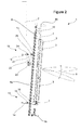
- FIG. 3 is a view similar to that of FIG. 2 , showing the antenna with the radome in place.
- FIG. 1 is a front view and FIG. 2 is a side view of a communications antenna 1 .
- the antenna 1 is mounted on a support 2 , which is shown as a pole but could be any supporting surface such as an antenna tower, building or other suitable support.
- the communications antenna 1 includes a cellular antenna including radiofrequency radiating elements 3 .
- the radiofrequency radiating elements 3 may be suitable for transmitting and/or receiving signals in a cellular communications network.
- the radio frequency radiating elements 3 may be suitable for use in a cellular base station antenna.
- a radiofrequency feed network 4 may feed signals to and/or from the radio frequency radiating elements 3 .
- a ground plane 5 may be situated behind the radio frequency radiating elements 3 .
- the radiofrequency radiating elements 3 produce a radiofrequency beam which has an adjustable azimuth angle, as depicted by the arrow 6 .
- Adjustment of the radiofrequency beam angle may be achieved by electrical or mechanical adjustment.
- the ground plane 5 may support the radio-frequency elements 3 and be mounted at each end on a rotating mount 7 within the antenna housing 8 . This allows the radio-frequency elements 3 to be rotated within the housing so as to alter the azimuth angle of the radiofrequency beam.
- the antenna housing 8 may include a back wall 8 a , a top wall 8 b and a bottom wall 8 c , as shown in FIG. 2 .
- the antenna housing 8 may be configured to receive an antenna radome 11 , as shown in FIG. 3 , such that the electrical components of the antenna are contained within an enclosure formed by the housing 8 and radome 11 .
- rotation of the groundplane 5 on the mounts 7 may result in movement of the groundplane with respect to the radome.
- the feed network may include a number of phase shifters for adjusting the phase of signals supplied to the individual radiating elements 3 . This allows adjustment of the downtilt angle of the radiofrequency antenna beam, as depicted by the arrow 9 in FIG. 2 .
- adjustment of the downtilt angle may be achieved by electrical means and adjustment of the azimuth angle may be achieved by mechanical means.
- adjustment of the azimuth and downtilt angles may be achieved by any combination of mechanical and electrical adjustment.
- both azimuth and downtilt angles may be adjusted by electrical phase shifters.
- arrangements for adjusting the beamwidth of the radio-frequency beam may also be provided.
- power dividers for dividing power supplied to the various radio frequency elements 3 may be used to adjust the beamwidth.
- the angle and beamwidth of the radiofrequency beam may be adjusted remotely, as discussed for example in the Applicant's US patent application publication nos. US2004/0038714A1, entitled “Cellular antenna”, and US2006/0244675A1, entitled “A cellular antenna and systems and methods therefor”. The disclosures of these documents are incorporated by reference herein.
- the communications antenna 1 also includes a point-to-point antenna 10 .
- This point-to-point antenna may be suitable for forming a backhaul communications link.
- the point-to-point antenna 10 may be a microwave antenna, such as a microwave dish or a planar microwave array.
- the point-to-point antenna 10 may be a highly directional antenna.
- the point-to-point antenna 10 is fixed with respect to the antenna radome 11 ( FIG. 3 ). This means that the point-to-point antenna 10 is oriented by orienting the point-to-point antenna 10 and radome together. This fixed arrangement may be achieved by fixing both the radome and the point-to-point antenna 10 to an antenna structure, or by fixing them together directly. Thus, orientation of the point-to-point antenna 10 and radome may or may not require orientation of the entire communications antenna 1 .
- the point-to-point antenna 10 may operate in a license band in which the radiation pattern must meet strict regulatory pattern envelopes. The effects of relative motion between the point-to-point antenna and the radome would then be particularly problematic.
- FIG. 2 shows that the communications antenna 1 may be mounted to the support 2 using a two-part mounting arrangement 12 , 13 , which may be situated outside the antenna housing.
- the bottom mount 13 may include a bracket 14 for mounting to the support 2 ; a second bracket 15 for mounting to the antenna 1 ; and a pivoting connection 16 joining the two brackets 14 , 15 .
- the top mount 12 may include a bracket 18 for mounting to the support 2 ; a second bracket 19 for mounting to the antenna 1 ; and a two-legged connection joining the two brackets 18 , 19 .
- the two-legged connection may include a first leg 21 joined to a second leg 22 at a central pivot 23 .
- Each leg 21 , 22 is joined to one of the brackets at a pivot 24 , 25 .
- the central pivot 23 includes a tightener (not shown) for fixing the two legs 21 , 22 at the appropriate angle.
- This mounting arrangement 12 , 13 allows the downtilt orientation of the antenna to be adjusted.
- the top mount 12 can be adjusted by altering the angle of the two legs 21 , 22 while the bottom mount 13 allows the antenna to rotate around pivot 16 .
- the azimuth orientation of the antenna can be adjusted either using the brackets 14 , 18 mounted on the support 2 or using a further pivot.
- the orientation of the antenna can be fixed in both downtilt and azimuth using the mounting arrangement 12 , 13 for mounting the antenna to a support 2 .
- the mounting arrangement may allow the antenna orientation to be adjusted after attachment to a support, or may simply allow the antenna to be fixed with a desired orientation.
- orientation of the point-to-point antenna 10 may be achieved by orienting the radome and point-to-point element together using the mounting arrangement 12 , 13 . This orientation will generally be performed at installation of the antenna, although changes in the network may necessitate reorientation at a later time.
- the radiofrequency beam is oriented using electrical or mechanical adjustment as described above.
- the antenna housing and radome may be mounted to a support using an antenna mounting arrangement.
- the groundplane for the radiofrequency elements may support those elements and may be mounted to the antenna housing, possibly so as to allow rotation of the groundplane within the antenna housing and radome.
- the point-to-point antenna may be mounted to the antenna housing and/or radome.
- the cellular antenna and point-to-point antenna may both be contained within the radome 11 .
- the methods and antennas described above allow for easy installation of point-to-point and radiofrequency radiators in a single unit. Alignment of the point-to-point element with the radome allows the antenna to meet the strict radiation pattern requirements for point-to-point links, which are typically microwave links. In contrast, systems with an adjustable point-to-point antenna within a radome (i.e. where the orientation of the point-to-point element is not fixed with respect to the radome) are likely to suffer from unpredictable and/or negative effects on the radiation pattern and return loss of the point-to-point antenna.
- the Applicant's antenna allows use of a point-to-point antenna embedded in a radiofrequency antenna, without the need to address the variable effects caused by adjustment of the point-to-point antenna with respect to the radome.
Landscapes
- Engineering & Computer Science (AREA)
- Computer Networks & Wireless Communication (AREA)
- Details Of Aerials (AREA)
- Support Of Aerials (AREA)
- Aerials With Secondary Devices (AREA)
- Variable-Direction Aerials And Aerial Arrays (AREA)
Priority Applications (1)
| Application Number | Priority Date | Filing Date | Title |
|---|---|---|---|
| US12/191,099 US8655409B2 (en) | 2007-08-30 | 2008-08-13 | Antenna with cellular and point-to-point communications capability |
Applications Claiming Priority (2)
| Application Number | Priority Date | Filing Date | Title |
|---|---|---|---|
| US96908407P | 2007-08-30 | 2007-08-30 | |
| US12/191,099 US8655409B2 (en) | 2007-08-30 | 2008-08-13 | Antenna with cellular and point-to-point communications capability |
Publications (2)
| Publication Number | Publication Date |
|---|---|
| US20090069055A1 US20090069055A1 (en) | 2009-03-12 |
| US8655409B2 true US8655409B2 (en) | 2014-02-18 |
Family
ID=40429631
Family Applications (1)
| Application Number | Title | Priority Date | Filing Date |
|---|---|---|---|
| US12/191,099 Expired - Fee Related US8655409B2 (en) | 2007-08-30 | 2008-08-13 | Antenna with cellular and point-to-point communications capability |
Country Status (8)
| Country | Link |
|---|---|
| US (1) | US8655409B2 (de) |
| EP (1) | EP2186165A4 (de) |
| JP (1) | JP5297461B2 (de) |
| KR (1) | KR20100051840A (de) |
| CN (1) | CN101855782B (de) |
| AU (1) | AU2008296656A1 (de) |
| MX (1) | MX2010002208A (de) |
| WO (1) | WO2009032496A2 (de) |
Cited By (3)
| Publication number | Priority date | Publication date | Assignee | Title |
|---|---|---|---|---|
| US10079423B2 (en) * | 2012-10-15 | 2018-09-18 | Telekom Malaysia Berhad | Apparatus for adjusting the tilt angle of an antenna |
| US10132098B1 (en) * | 2017-05-16 | 2018-11-20 | Atc Ip Llc | Non-disruptive reinforcement of telecommunications towers |
| US10777873B2 (en) * | 2016-12-08 | 2020-09-15 | At&T Intellectual Property I, L.P. | Method and apparatus for mounting network devices |
Families Citing this family (7)
| Publication number | Priority date | Publication date | Assignee | Title |
|---|---|---|---|---|
| KR20090033403A (ko) * | 2000-07-10 | 2009-04-02 | 앤드류 코포레이션 | 셀룰러 안테나 |
| KR101103674B1 (ko) | 2010-06-01 | 2012-01-11 | 엘지이노텍 주식회사 | 발광 소자 |
| EP2629592A1 (de) * | 2012-02-15 | 2013-08-21 | Alcatel Lucent | Anschlusskasten, Hauptkasten und Basisstation-Sender-Empfänger |
| CN104409854B (zh) * | 2014-12-04 | 2017-02-22 | 武汉虹信通信技术有限责任公司 | 一种电调天线旋转标尺的调节装置 |
| CN104466362A (zh) * | 2014-12-12 | 2015-03-25 | 浙江佳源通讯技术有限公司 | 一种高增益多频段高铁覆盖板状天线 |
| CN105990635A (zh) * | 2015-01-29 | 2016-10-05 | 康普技术有限责任公司 | 用于降低小型基站天线振动频率传递的装置和方法 |
| WO2018099565A1 (en) | 2016-12-01 | 2018-06-07 | Huawei Technologies Co., Ltd. | Antenna tilt drive |
Citations (17)
| Publication number | Priority date | Publication date | Assignee | Title |
|---|---|---|---|---|
| US5097647A (en) | 1990-11-09 | 1992-03-24 | Canadian Communications Structures Inc. | Support tower for communications equipment |
| JPH052421A (ja) | 1991-06-24 | 1993-01-08 | Toyota Central Res & Dev Lab Inc | 無人搬送車の制御装置 |
| JPH0578018A (ja) | 1991-09-19 | 1993-03-30 | Murata Mach Ltd | 自動ワインダの解舒補助装置 |
| JP2001230719A (ja) | 2000-02-17 | 2001-08-24 | Furukawa Electric Co Ltd:The | 放送波中継システム |
| DE20111727U1 (de) | 2001-07-11 | 2001-10-18 | FIBER-TECH Products GmbH, 09116 Chemnitz | Integrierte Hohlkörper-Antennen-Anordnung |
| JP2002223106A (ja) | 2001-01-29 | 2002-08-09 | Harada Ind Co Ltd | アンテナ取付け装置 |
| US6573875B2 (en) * | 2001-02-19 | 2003-06-03 | Andrew Corporation | Antenna system |
| US20040038714A1 (en) | 2000-07-10 | 2004-02-26 | Daniel Rhodes | Cellular Antenna |
| US20040162115A1 (en) | 2003-02-14 | 2004-08-19 | Martin Smith | Wireless antennas, networks, methods, software, and services |
| US20050134512A1 (en) | 2003-12-18 | 2005-06-23 | Kathrein-Werke Kg, | Mobile radio antenna arrangement for a base station |
| WO2005062419A1 (en) | 2003-12-23 | 2005-07-07 | Kmw Inc. | Antenna beam control apparatus for base transceiver station antennas |
| US20060003808A1 (en) * | 2002-10-19 | 2006-01-05 | Quintel Technology Limited | Mobile radio base station |
| US20060192716A1 (en) * | 2004-01-02 | 2006-08-31 | Duk-Yong Kim | Antenna beam controlling system for cellular communication |
| US20060244675A1 (en) * | 2001-07-10 | 2006-11-02 | Elliot Robert D | Cellular antenna and systems and methods therefor |
| US20070085744A1 (en) * | 2005-10-16 | 2007-04-19 | Starling Advanced Communications Ltd. | Dual polarization planar array antenna and cell elements therefor |
| US20070241979A1 (en) * | 2003-06-16 | 2007-10-18 | Ching-Shun Yang | Base station antenna rotation mechanism |
| US7642988B1 (en) * | 2006-06-19 | 2010-01-05 | Sprint Communications Company L.P. | Multi-link antenna array configured for cellular site placement |
Family Cites Families (5)
| Publication number | Priority date | Publication date | Assignee | Title |
|---|---|---|---|---|
| JPH052421U (ja) * | 1991-04-02 | 1993-01-14 | 三菱電機株式会社 | アンテナ装置 |
| JPH0578018U (ja) * | 1992-03-27 | 1993-10-22 | 三菱電機株式会社 | アンテナ装置 |
| US6006069A (en) * | 1994-11-28 | 1999-12-21 | Bosch Telecom Gmbh | Point-to-multipoint communications system |
| JPH08340211A (ja) * | 1995-06-12 | 1996-12-24 | Sumitomo Electric Ind Ltd | アレイアンテナ |
| US6885343B2 (en) * | 2002-09-26 | 2005-04-26 | Andrew Corporation | Stripline parallel-series-fed proximity-coupled cavity backed patch antenna array |
-
2008
- 2008-08-13 WO PCT/US2008/073040 patent/WO2009032496A2/en not_active Ceased
- 2008-08-13 MX MX2010002208A patent/MX2010002208A/es active IP Right Grant
- 2008-08-13 CN CN200880104437.2A patent/CN101855782B/zh not_active Expired - Fee Related
- 2008-08-13 JP JP2010523026A patent/JP5297461B2/ja not_active Expired - Fee Related
- 2008-08-13 KR KR1020107004659A patent/KR20100051840A/ko not_active Abandoned
- 2008-08-13 EP EP08797808.6A patent/EP2186165A4/de not_active Withdrawn
- 2008-08-13 US US12/191,099 patent/US8655409B2/en not_active Expired - Fee Related
- 2008-08-13 AU AU2008296656A patent/AU2008296656A1/en not_active Abandoned
Patent Citations (18)
| Publication number | Priority date | Publication date | Assignee | Title |
|---|---|---|---|---|
| US5097647A (en) | 1990-11-09 | 1992-03-24 | Canadian Communications Structures Inc. | Support tower for communications equipment |
| JPH052421A (ja) | 1991-06-24 | 1993-01-08 | Toyota Central Res & Dev Lab Inc | 無人搬送車の制御装置 |
| JPH0578018A (ja) | 1991-09-19 | 1993-03-30 | Murata Mach Ltd | 自動ワインダの解舒補助装置 |
| JP2001230719A (ja) | 2000-02-17 | 2001-08-24 | Furukawa Electric Co Ltd:The | 放送波中継システム |
| US20040038714A1 (en) | 2000-07-10 | 2004-02-26 | Daniel Rhodes | Cellular Antenna |
| JP2002223106A (ja) | 2001-01-29 | 2002-08-09 | Harada Ind Co Ltd | アンテナ取付け装置 |
| US6573875B2 (en) * | 2001-02-19 | 2003-06-03 | Andrew Corporation | Antenna system |
| US20060244675A1 (en) * | 2001-07-10 | 2006-11-02 | Elliot Robert D | Cellular antenna and systems and methods therefor |
| DE20111727U1 (de) | 2001-07-11 | 2001-10-18 | FIBER-TECH Products GmbH, 09116 Chemnitz | Integrierte Hohlkörper-Antennen-Anordnung |
| US20060003808A1 (en) * | 2002-10-19 | 2006-01-05 | Quintel Technology Limited | Mobile radio base station |
| US20040162115A1 (en) | 2003-02-14 | 2004-08-19 | Martin Smith | Wireless antennas, networks, methods, software, and services |
| US20070241979A1 (en) * | 2003-06-16 | 2007-10-18 | Ching-Shun Yang | Base station antenna rotation mechanism |
| US7015871B2 (en) * | 2003-12-18 | 2006-03-21 | Kathrein-Werke Kg | Mobile radio antenna arrangement for a base station |
| US20050134512A1 (en) | 2003-12-18 | 2005-06-23 | Kathrein-Werke Kg, | Mobile radio antenna arrangement for a base station |
| WO2005062419A1 (en) | 2003-12-23 | 2005-07-07 | Kmw Inc. | Antenna beam control apparatus for base transceiver station antennas |
| US20060192716A1 (en) * | 2004-01-02 | 2006-08-31 | Duk-Yong Kim | Antenna beam controlling system for cellular communication |
| US20070085744A1 (en) * | 2005-10-16 | 2007-04-19 | Starling Advanced Communications Ltd. | Dual polarization planar array antenna and cell elements therefor |
| US7642988B1 (en) * | 2006-06-19 | 2010-01-05 | Sprint Communications Company L.P. | Multi-link antenna array configured for cellular site placement |
Non-Patent Citations (4)
| Title |
|---|
| PCT/US2008/073040 International Seach Report for related application. |
| PCT/US2008/073040 Written Opinion for related application. |
| Supplementary European Search Report for relation App. No. 08797808.6 dated May 31, 2013. |
| Translation of Office Action for related Japanese Patent Application No. 2010-523026 dated Dec. 20, 2012. |
Cited By (4)
| Publication number | Priority date | Publication date | Assignee | Title |
|---|---|---|---|---|
| US10079423B2 (en) * | 2012-10-15 | 2018-09-18 | Telekom Malaysia Berhad | Apparatus for adjusting the tilt angle of an antenna |
| US10777873B2 (en) * | 2016-12-08 | 2020-09-15 | At&T Intellectual Property I, L.P. | Method and apparatus for mounting network devices |
| US10132098B1 (en) * | 2017-05-16 | 2018-11-20 | Atc Ip Llc | Non-disruptive reinforcement of telecommunications towers |
| US10519684B2 (en) | 2017-05-16 | 2019-12-31 | Atc Ip Llc | Non-disruptive reinforcement of telecommunications towers |
Also Published As
| Publication number | Publication date |
|---|---|
| JP2010538541A (ja) | 2010-12-09 |
| MX2010002208A (es) | 2010-03-31 |
| CN101855782A (zh) | 2010-10-06 |
| WO2009032496A2 (en) | 2009-03-12 |
| AU2008296656A1 (en) | 2009-03-12 |
| KR20100051840A (ko) | 2010-05-18 |
| JP5297461B2 (ja) | 2013-09-25 |
| WO2009032496A3 (en) | 2009-06-04 |
| EP2186165A4 (de) | 2013-07-03 |
| US20090069055A1 (en) | 2009-03-12 |
| CN101855782B (zh) | 2014-11-26 |
| EP2186165A2 (de) | 2010-05-19 |
Similar Documents
| Publication | Publication Date | Title |
|---|---|---|
| US8655409B2 (en) | Antenna with cellular and point-to-point communications capability | |
| EP3939119B1 (de) | Strahlungselemente mit angewinkelten speisungsstielen und diese enthaltende basisstationsantennen | |
| US11335995B2 (en) | Base station antennas including supplemental arrays | |
| EP3863116B1 (de) | Wickelantenne | |
| US7498988B2 (en) | Antenna element, feed probe; dielectric spacer, antenna and method of communicating with a plurality of devices | |
| US7006053B2 (en) | Adjustable reflector system for fixed dipole antenna | |
| US20220181786A1 (en) | Meta-structure based reflectarrays for enhanced wireless applications | |
| JP2004056643A (ja) | アンテナ装置 | |
| US20050003864A1 (en) | Antenna system | |
| US7095383B2 (en) | Field configurable radiation antenna device | |
| US20260031547A1 (en) | Base station antennas having an active antenna module(s) and related mounting systems and methods | |
| CA3172688C (en) | Radiating elements having angled feed stalks and base station antennas including same | |
| KR100525313B1 (ko) | Shorting 포인트를 갖는 L-Probe 급전 구조의 급전방식을 이용한 패치 안테나 | |
| WO2026036942A1 (zh) | 一种天线、通信设备和通信系统 | |
| WO2026036932A1 (zh) | 一种天线、通信设备和通信系统 | |
| KR20040037052A (ko) | 다이폴 소자를 이용한 광대역 패치 안테나 |
Legal Events
| Date | Code | Title | Description |
|---|---|---|---|
| AS | Assignment |
Owner name: BANK OF AMERICA, N.A., AS ADMINISTRATIVE AGENT, CA Free format text: PATENT SECURITY AGREEMENT SUPPLEMENT;ASSIGNORS:COMMSCOPE OF NORTH CAROLINA;ANDREW LLC;REEL/FRAME:021930/0863 Effective date: 20081205 Owner name: BANK OF AMERICA, N.A., AS ADMINISTRATIVE AGENT,CAL Free format text: PATENT SECURITY AGREEMENT SUPPLEMENT;ASSIGNORS:COMMSCOPE OF NORTH CAROLINA;ANDREW LLC;REEL/FRAME:021930/0863 Effective date: 20081205 |
|
| AS | Assignment |
Owner name: ANDREW LLC (F/K/A ANDREW CORPORATION), NORTH CAROLINA Free format text: PATENT RELEASE;ASSIGNOR:BANK OF AMERICA, N.A., AS ADMINISTRATIVE AGENT;REEL/FRAME:026039/0005 Effective date: 20110114 Owner name: ALLEN TELECOM LLC, NORTH CAROLINA Free format text: PATENT RELEASE;ASSIGNOR:BANK OF AMERICA, N.A., AS ADMINISTRATIVE AGENT;REEL/FRAME:026039/0005 Effective date: 20110114 Owner name: ANDREW LLC (F/K/A ANDREW CORPORATION), NORTH CAROL Free format text: PATENT RELEASE;ASSIGNOR:BANK OF AMERICA, N.A., AS ADMINISTRATIVE AGENT;REEL/FRAME:026039/0005 Effective date: 20110114 Owner name: COMMSCOPE, INC. OF NORTH CAROLINA, NORTH CAROLINA Free format text: PATENT RELEASE;ASSIGNOR:BANK OF AMERICA, N.A., AS ADMINISTRATIVE AGENT;REEL/FRAME:026039/0005 Effective date: 20110114 |
|
| AS | Assignment |
Owner name: JPMORGAN CHASE BANK, N.A., AS COLLATERAL AGENT, NEW YORK Free format text: SECURITY AGREEMENT;ASSIGNORS:ALLEN TELECOM LLC, A DELAWARE LLC;ANDREW LLC, A DELAWARE LLC;COMMSCOPE, INC. OF NORTH CAROLINA, A NORTH CAROLINA CORPORATION;REEL/FRAME:026276/0363 Effective date: 20110114 Owner name: JPMORGAN CHASE BANK, N.A., AS COLLATERAL AGENT, NE Free format text: SECURITY AGREEMENT;ASSIGNORS:ALLEN TELECOM LLC, A DELAWARE LLC;ANDREW LLC, A DELAWARE LLC;COMMSCOPE, INC. OF NORTH CAROLINA, A NORTH CAROLINA CORPORATION;REEL/FRAME:026276/0363 Effective date: 20110114 |
|
| AS | Assignment |
Owner name: JPMORGAN CHASE BANK, N.A., AS COLLATERAL AGENT, NEW YORK Free format text: SECURITY AGREEMENT;ASSIGNORS:ALLEN TELECOM LLC, A DELAWARE LLC;ANDREW LLC, A DELAWARE LLC;COMMSCOPE, INC OF NORTH CAROLINA, A NORTH CAROLINA CORPORATION;REEL/FRAME:026272/0543 Effective date: 20110114 Owner name: JPMORGAN CHASE BANK, N.A., AS COLLATERAL AGENT, NE Free format text: SECURITY AGREEMENT;ASSIGNORS:ALLEN TELECOM LLC, A DELAWARE LLC;ANDREW LLC, A DELAWARE LLC;COMMSCOPE, INC OF NORTH CAROLINA, A NORTH CAROLINA CORPORATION;REEL/FRAME:026272/0543 Effective date: 20110114 |
|
| AS | Assignment |
Owner name: WILMINGTON TRUST, NATIONAL ASSOCIATION, AS COLLATERAL AGENT, CONNECTICUT Free format text: SECURITY INTEREST;ASSIGNORS:ALLEN TELECOM LLC;COMMSCOPE TECHNOLOGIES LLC;COMMSCOPE, INC. OF NORTH CAROLINA;AND OTHERS;REEL/FRAME:036201/0283 Effective date: 20150611 Owner name: WILMINGTON TRUST, NATIONAL ASSOCIATION, AS COLLATE Free format text: SECURITY INTEREST;ASSIGNORS:ALLEN TELECOM LLC;COMMSCOPE TECHNOLOGIES LLC;COMMSCOPE, INC. OF NORTH CAROLINA;AND OTHERS;REEL/FRAME:036201/0283 Effective date: 20150611 |
|
| AS | Assignment |
Owner name: REDWOOD SYSTEMS, INC., NORTH CAROLINA Free format text: RELEASE OF SECURITY INTEREST PATENTS (RELEASES RF 036201/0283);ASSIGNOR:WILMINGTON TRUST, NATIONAL ASSOCIATION;REEL/FRAME:042126/0434 Effective date: 20170317 Owner name: ALLEN TELECOM LLC, NORTH CAROLINA Free format text: RELEASE OF SECURITY INTEREST PATENTS (RELEASES RF 036201/0283);ASSIGNOR:WILMINGTON TRUST, NATIONAL ASSOCIATION;REEL/FRAME:042126/0434 Effective date: 20170317 Owner name: COMMSCOPE, INC. OF NORTH CAROLINA, NORTH CAROLINA Free format text: RELEASE OF SECURITY INTEREST PATENTS (RELEASES RF 036201/0283);ASSIGNOR:WILMINGTON TRUST, NATIONAL ASSOCIATION;REEL/FRAME:042126/0434 Effective date: 20170317 Owner name: COMMSCOPE TECHNOLOGIES LLC, NORTH CAROLINA Free format text: RELEASE OF SECURITY INTEREST PATENTS (RELEASES RF 036201/0283);ASSIGNOR:WILMINGTON TRUST, NATIONAL ASSOCIATION;REEL/FRAME:042126/0434 Effective date: 20170317 |
|
| FEPP | Fee payment procedure |
Free format text: MAINTENANCE FEE REMINDER MAILED (ORIGINAL EVENT CODE: REM.) |
|
| LAPS | Lapse for failure to pay maintenance fees |
Free format text: PATENT EXPIRED FOR FAILURE TO PAY MAINTENANCE FEES (ORIGINAL EVENT CODE: EXP.) |
|
| STCH | Information on status: patent discontinuation |
Free format text: PATENT EXPIRED DUE TO NONPAYMENT OF MAINTENANCE FEES UNDER 37 CFR 1.362 |
|
| FP | Lapsed due to failure to pay maintenance fee |
Effective date: 20180218 |
|
| AS | Assignment |
Owner name: REDWOOD SYSTEMS, INC., NORTH CAROLINA Free format text: RELEASE BY SECURED PARTY;ASSIGNOR:JPMORGAN CHASE BANK, N.A.;REEL/FRAME:048840/0001 Effective date: 20190404 Owner name: COMMSCOPE, INC. OF NORTH CAROLINA, NORTH CAROLINA Free format text: RELEASE BY SECURED PARTY;ASSIGNOR:JPMORGAN CHASE BANK, N.A.;REEL/FRAME:048840/0001 Effective date: 20190404 Owner name: COMMSCOPE TECHNOLOGIES LLC, NORTH CAROLINA Free format text: RELEASE BY SECURED PARTY;ASSIGNOR:JPMORGAN CHASE BANK, N.A.;REEL/FRAME:048840/0001 Effective date: 20190404 Owner name: ANDREW LLC, NORTH CAROLINA Free format text: RELEASE BY SECURED PARTY;ASSIGNOR:JPMORGAN CHASE BANK, N.A.;REEL/FRAME:048840/0001 Effective date: 20190404 Owner name: ALLEN TELECOM LLC, ILLINOIS Free format text: RELEASE BY SECURED PARTY;ASSIGNOR:JPMORGAN CHASE BANK, N.A.;REEL/FRAME:048840/0001 Effective date: 20190404 Owner name: COMMSCOPE TECHNOLOGIES LLC, NORTH CAROLINA Free format text: RELEASE BY SECURED PARTY;ASSIGNOR:JPMORGAN CHASE BANK, N.A.;REEL/FRAME:049260/0001 Effective date: 20190404 Owner name: ALLEN TELECOM LLC, ILLINOIS Free format text: RELEASE BY SECURED PARTY;ASSIGNOR:JPMORGAN CHASE BANK, N.A.;REEL/FRAME:049260/0001 Effective date: 20190404 Owner name: REDWOOD SYSTEMS, INC., NORTH CAROLINA Free format text: RELEASE BY SECURED PARTY;ASSIGNOR:JPMORGAN CHASE BANK, N.A.;REEL/FRAME:049260/0001 Effective date: 20190404 Owner name: COMMSCOPE, INC. OF NORTH CAROLINA, NORTH CAROLINA Free format text: RELEASE BY SECURED PARTY;ASSIGNOR:JPMORGAN CHASE BANK, N.A.;REEL/FRAME:049260/0001 Effective date: 20190404 Owner name: ANDREW LLC, NORTH CAROLINA Free format text: RELEASE BY SECURED PARTY;ASSIGNOR:JPMORGAN CHASE BANK, N.A.;REEL/FRAME:049260/0001 Effective date: 20190404 |