US8662704B2 - LED optical system with multiple levels of secondary optics - Google Patents
LED optical system with multiple levels of secondary optics Download PDFInfo
- Publication number
- US8662704B2 US8662704B2 US12/851,319 US85131910A US8662704B2 US 8662704 B2 US8662704 B2 US 8662704B2 US 85131910 A US85131910 A US 85131910A US 8662704 B2 US8662704 B2 US 8662704B2
- Authority
- US
- United States
- Prior art keywords
- optic
- lighting system
- light rays
- diode
- prismatic
- Prior art date
- Legal status (The legal status is an assumption and is not a legal conclusion. Google has not performed a legal analysis and makes no representation as to the accuracy of the status listed.)
- Active, expires
Links
Images


Classifications
-
- F—MECHANICAL ENGINEERING; LIGHTING; HEATING; WEAPONS; BLASTING
- F21—LIGHTING
- F21V—FUNCTIONAL FEATURES OR DETAILS OF LIGHTING DEVICES OR SYSTEMS THEREOF; STRUCTURAL COMBINATIONS OF LIGHTING DEVICES WITH OTHER ARTICLES, NOT OTHERWISE PROVIDED FOR
- F21V5/00—Refractors for light sources
- F21V5/04—Refractors for light sources of lens shape
-
- F—MECHANICAL ENGINEERING; LIGHTING; HEATING; WEAPONS; BLASTING
- F21—LIGHTING
- F21S—NON-PORTABLE LIGHTING DEVICES; SYSTEMS THEREOF; VEHICLE LIGHTING DEVICES SPECIALLY ADAPTED FOR VEHICLE EXTERIORS
- F21S8/00—Lighting devices intended for fixed installation
- F21S8/08—Lighting devices intended for fixed installation with a standard
-
- F—MECHANICAL ENGINEERING; LIGHTING; HEATING; WEAPONS; BLASTING
- F21—LIGHTING
- F21W—INDEXING SCHEME ASSOCIATED WITH SUBCLASSES F21K, F21L, F21S and F21V, RELATING TO USES OR APPLICATIONS OF LIGHTING DEVICES OR SYSTEMS
- F21W2131/00—Use or application of lighting devices or systems not provided for in codes F21W2102/00-F21W2121/00
- F21W2131/10—Outdoor lighting
- F21W2131/103—Outdoor lighting of streets or roads
-
- F—MECHANICAL ENGINEERING; LIGHTING; HEATING; WEAPONS; BLASTING
- F21—LIGHTING
- F21Y—INDEXING SCHEME ASSOCIATED WITH SUBCLASSES F21K, F21L, F21S and F21V, RELATING TO THE FORM OR THE KIND OF THE LIGHT SOURCES OR OF THE COLOUR OF THE LIGHT EMITTED
- F21Y2105/00—Planar light sources
- F21Y2105/10—Planar light sources comprising a two-dimensional [2D] array of point-like light-generating elements
-
- F—MECHANICAL ENGINEERING; LIGHTING; HEATING; WEAPONS; BLASTING
- F21—LIGHTING
- F21Y—INDEXING SCHEME ASSOCIATED WITH SUBCLASSES F21K, F21L, F21S and F21V, RELATING TO THE FORM OR THE KIND OF THE LIGHT SOURCES OR OF THE COLOUR OF THE LIGHT EMITTED
- F21Y2115/00—Light-generating elements of semiconductor light sources
- F21Y2115/10—Light-emitting diodes [LED]
Definitions
- the present invention relates to lighting systems, in particular lighting systems using light emitting diodes to illuminate a target surface.
- a luminaire or light fixture includes at least a light source (or lamp), electrical components and a housing.
- a standard luminaire for illumination of surfaces, areas or objects typically uses a single light source and may include an optical arrangement to control raw light output from the single light source for more efficient distribution of the light.
- the optical arrangement can be a lens, a refractor, a reflector, or a combination of these optical elements that controls the light and produces a desired illumination pattern or distribution.
- LEDs Light emitting diodes
- LEDs Light emitting diodes
- a standard light source such as fluorescent, high intensity discharge, or incandescent.
- the total light output of LEDs requires optical control to make it perform properly and maximize the light coverage over a surface or area.
- LEDs In order to produce the equivalent amount of light of a high wattage standard lamp source, a large array of LED can be used although LEDs also differ in their raw light output. Most standard lamp sources produce a radial illumination pattern that is generally uniform in all directions and emanates from a single area on or within the lamp such as a filament or arc tube. However, LEDs produce a Lambertian distribution which only emanates from the front of the diodes and is not uniform in all directions. As such, most LEDs have a built-in lens to control the raw light output in a primary fashion, but a primary lens or optic has not proven to provide the necessary optical control to provide illumination patterns that are suitable to replace standard luminaire optical systems and lamp sources.
- Some LED systems may use a secondary-type optic repeated over each individual diode of the LED array. These types of LED systems have not yet proven to exceed the light distributions of standard lamp sources. Typically, their distributions fall short or they have similar amounts of waste light due to only having one level of control used over the LED array.
- an LED array with primary optics and multiple levels of secondary optics, where each level of secondary optics can be precisely aimed so that the array provides a more uniform distribution. It is desirable for such an LED array to have a larger, more efficient light distribution and meet or exceed standard type lamp systems. In a practical manner, an LED system with multiple levels of secondary optics would be superior as these secondary optics can be aimed and combined to produce different distribution shapes to more effectively light surfaces or areas.
- the present invention recognizes principles of illumination with a goal of mimicking the intensity distribution desirable to perfectly or uniformly illuminate surfaces from a luminaire.
- a “perfect” intensity distribution would see all light emitted from the luminaire become incident on a target plane in a uniform manner. Such a distribution would also generally eliminate all waste light, thereby gaining efficiency through the light distribution produced on the target surface or area. While a “perfect” distribution is virtually impossible to achieve, an ideal or otherwise superior optical system providing high uniformity, maximum light on the target area or surface with minimal waste light is possible.
- the present invention relates to an optical system used in lighting fixtures, or luminaires, where light emitting diodes (LEDs) arranged in a 2-D array are multiple sources of light used to illuminate surfaces, areas, or objects.
- the system efficiently controls raw light distribution or output of each individual LED within the array through the use of optics.
- the system makes better use of the raw LED light output, directing it more efficiently over a larger area or surface.
- raw output of the LEDs are trained by the optics into different patterns. By precisely aiming each individual LED optic and combining their illumination patterns, unique light patterns can be achieved which more efficiently light areas and surfaces than previous methods.
- a lighting system of the present invention comprises a framework carrying a plurality of diodes, where each diode has an associated optic.
- the optics populating the framework are a selected combination of optics of different levels or categories, for example, the categories of “high,” “medium” and “low,” where each category is defined by a predetermined range of vertical reflectance angles and a predetermined range of horizontal reflectance angles, as provided by prismatic portion(s) or “teeth” that refract and reflect light rays in a predetermined manner.
- the ranges of vertical and horizontal reflectance angles of different categories advantageously overlap so that the illumination patterns of different categories can blend to generally uniformly illuminate a target surface without dark spots or regions.
- an optic can have one or more prismatic portion or tooth.
- an optic of the “high” category (or “high” optic) has one prismatic portion
- an optic of the “medium” category (or “medium” optic) has two prismatic portions
- an optic of the “low” category (or “low” optic) has at least three, if not four, prismatic portions.
- the high optic has a vertical reflectance angle range of about twenty degrees, between about 60 to 80 degrees measured from nadir, and a horizontal reflectance angle range of about twenty degrees, between about ⁇ 10 to +10 degrees.
- the medium optic has a vertical reflectance angle range of about twenty degrees, between about 50 to 70 degrees measured from nadir, and a horizontal reflectance angle range of about forty degrees, between about ⁇ 20 to +20 degrees.
- the low optic has a vertical reflectance angle range of about fifty degrees, between about 0 to 50 degrees measured from nadir, and a horizontal reflectance angle range of about one hundred eighty degrees, between about ⁇ 90 to +90 degrees.
- a lighting system of the present invention includes a first plate member carrying diodes and a second plate member carrying optical members, one for each diode.
- Each optical member includes a primary optic for collecting and collimating light from its respective diode and a secondary optic for emitting the light within a predetermined range of vertical angles and a predetermined range of horizontal angles in accordance with the category of high, medium or low of the secondary optic.
- each optical member has alignment members or indicia that provide information and/or enable alignment and positioning of the optical member on the second plate member.
- each secondary optic has at least one prismatic portion or “tooth”, where each tooth has a rear (or reflective) surface that reflects collimated light rays which exit the optic from a front (or exiting) surface toward a target surface.
- Each tooth has a “swept” geometry for better angular (vertical and/or horizontal) control of light rays, where structural variations between teeth of different categories of secondary optics reside in various factors, including plurality of teeth, length of the tooth along the longitudinal axis A, curvature(s) in the vertical and/or horizontal directions, and angularity or tightness of curvature of the swept geometry.
- each tooth can be curved, with selected teeth having surfaces with curvature in more than one direction and/or multiple curvatures in any one direction.
- These curvatures serve to reflect and direct the light out of the tooth in different spatial distributions, where a milder, more open curvature provides a narrower distribution and a stronger, tighter curvature provides a wider distribution.
- These curvatures can control the exiting light in both the horizontal and/or vertical directions and the length of a tooth is predetermined to avoid light ray occlusion by adjacent optical members.
- FIG. 1 is a schematic of a light source providing illumination at point P on a target surface.
- FIG. 2 is a schematic of the light source of FIG. 1 providing illumination to a plurality of points on a target surface.
- FIG. 3 is a graph showing intensity I of a luminaire in units of candela versus vertical angle ⁇ in units of feet.
- FIG. 4 a is a vertical polar plot of illuminance intensity of a diode.
- FIG. 4 b is a horizontal polar plot of illuminance intensity of a diode.
- FIG. 4 c is a isometric 3-D graph of a cone of constant illuminance of a diode.
- FIG. 4 d is a 2-D graph of a base of the cone of FIG. 4 c.
- FIG. 5 is a perspective view of an embodiment of an LED optical system in accordance with the present invention.
- FIG. 6 is a partially-exploded view of the LED optical system of FIG. 5 .
- FIG. 7 is a bottom view of the LED optical system of FIG. 5 .
- FIG. 8 is a front elevational view of the LED optical system of FIG. 5 .
- FIG. 9 is a rear elevational view of the LED optical system of FIG. 5 .
- FIG. 10 a is a side elevational view of an embodiment of a “high” optical member in accordance with the present invention.
- FIG. 10 b is a side elevational view of an embodiment of a “medium” optical member in accordance with the present invention.
- FIG. 10 c is a side elevational view of an embodiment of a “low” optical member in accordance with the present invention.
- FIG. 11 a is a isometric view of an embodiment of a primary optic in accordance with the present invention.
- FIG. 11 b is a side cross-sectional view of the primary optic of FIG. 11 a.
- FIG. 11 c is a side elevational view of the primary optic of FIG. 11 a illustrating collimation of light rays.
- FIG. 11 d is a side elevational view of the primary optic of FIG. 11 a.
- FIG. 12 a is a vertical polar plot of illuminance intensity of a diode equipped with a low optical member of FIG. 10 c.
- FIG. 12 b is a horizontal polar plot of illuminance intensity of the equipped diode of FIG. 12 a.
- FIG. 12 c is a isometric 3-D graph of a cone of constant illuminance of the equipped diode of FIG. 12 a.
- FIG. 12 d is a 2-D graph of a base of the cone of FIG. 12 c.
- FIG. 13 a is a vertical polar plot of illuminance intensity of a diode equipped with a medium optical member of FIG. 10 b.
- FIG. 13 b is a horizontal polar plot of illuminance intensity of the equipped diode of FIG. 13 a.
- FIG. 13 c is a isometric 3-D graph of a cone of constant illuminance of the equipped diode of FIG. 13 a.
- FIG. 13 d is a 2-D graph of a base of the cone of FIG. 13 c.
- FIG. 14 a is a vertical polar plot of illuminance intensity of a diode equipped with a high optical member of FIG. 10 a.
- FIG. 14 b is a horizontal polar plot of illuminance intensity of the equipped diode of FIG. 14 a.
- FIG. 14 c is a isometric 3-D graph of a cone of constant illuminance of the equipped diode of FIG. 14 a.
- FIG. 14 d is a 2-D graph of a base of the cone of FIG. 14 c.
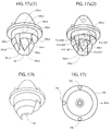
- FIG. 15 a is a bottom isometric view of an embodiment of a “high” optical member in accordance with the present invention.
- FIG. 15 b is a rear isometric view of the “high” optical member of FIG. 15 a.
- FIG. 15 c is a top plan view of the “high” optical member of FIG. 15 a.
- FIG. 15 d is a rear elevational view of the “high” optical member of FIG. 15 a.
- FIG. 15 e is a side elevational view of the “high” optical member of FIG. 15 a.
- FIG. 15 f is a front elevational view of the “high” optical member of FIG. 15 a.
- FIG. 15 g is a bottom plan view of the “high” optical member of FIG. 15 a.
- FIG. 15 h is a side elevational view of the “high” optical member illustrating refraction and total internal reflection of light rays.
- FIG. 16 a is a front isometric view of an embodiment of a “medium” optical member in accordance with the present invention.
- FIG. 16 b is a rear isometric view of the “medium” optical member of FIG. 16 a.
- FIG. 16 c is a top plan view of the “medium” optical member of FIG. 16 a.
- FIG. 16 d is a rear elevational view of the “medium” optical member of FIG. 16 a.
- FIG. 16 e is a side elevational view of the “medium” optical member of FIG. 16 a.
- FIG. 16 f is a front elevational view of the “medium” optical member of FIG. 16 a.
- FIG. 16 g is a bottom plan view of the “medium” optical member of FIG. 16 a.
- FIG. 16 h is a side elevational view of the “medium” optical member illustrating refraction and total internal reflection of light rays.
- FIG. 17 a ( 1 ) is a front isometric view of an embodiment of a “low” optical member in accordance with the present invention.
- FIG. 17 a ( 1 ) is a front isometric view of the “low” optical member of FIG. 17 a ( 1 ), with hidden lines.
- FIG. 17 b is a rear isometric view of the “low” optical member of FIG. 17 a.
- FIG. 17 c is a top plan view of the “low” optical member of FIG. 17 a.
- FIG. 17 d is a rear elevational view of the “low” optical member of FIG. 17 a.
- FIG. 17 e is a side elevational view of the “low” optical member of FIG. 17 a.
- FIG. 17 f is a front elevational view of the “low” optical member of FIG. 17 a.
- FIG. 17 g is a bottom plan view of the “low” optical member of FIG. 17 a.
- FIG. 17 h is a side elevational view of the “low” optical member illustrating refraction and total internal reflection of light rays.
- FIG. 18 is a top plan view of LED optical system of FIG. 5 .
- FIGS. 19 a - 19 i are various embodiments of an LED plate of the present invention.
- FIG. 20 is a schematic of an LED optical system of the present invention illuminating a target surface from a vertical distance of h.
- FIGS. 21 a - 21 h are plan views of various overlapping illumination patterns provided by LED optical systems in accordance with the present invention.
- the present invention aims to create a perfect intensity distribution by starting with the following equation for illuminance Ep at point P, where the point or location P is on target area or surface TP (x-y plane) illuminated by a light source or Luminaire L a distance h above (or away from the source) along z axis (or Nadir).
- Ep I ( ⁇ , ⁇ )*cos( ⁇ )/ D 2 Eqn (1)
- Equation (5) shows that the intensity I required is directly proportional to the inverse of the cosine cubed of the vertical angle.
- the intensity is strongest directly below the diode and follows a cosine type falloff as the vertical angle ⁇ goes to 90 degrees. However, these intensities are equal in all directions laterally ( ⁇ ranging from 0 to 360 degrees) as shown in the horizontal polar plot of FIG. 4 b . If used to illuminate the target surface TP below, the diode 14 emits a 3-dimensional, radially symmetrical volume or of constant illuminance C (with normal height h), as shown in isometric view of FIG.
- FIG. 4 d a target plane grid TP is illustrated with a spacing grid equal to the normal height h.
- the area of the base B spans less than four squares on the target grid TP.
- the present invention advantageously controls light from one location over the target and illuminates the target surface from that location, using optical members, each comprising a primary optic and a secondary optic, designed to control total light output of each diode.
- optical members each comprising a primary optic and a secondary optic, designed to control total light output of each diode.
- different categories or types of secondary optics are used to apply optical properties of the underlying construction material and incorporate different specialized geometries that train the raw LED distribution into a more useful one.
- the present invention advantageously considers several practical limitations in providing an optical system that mimics the perfect intensity distribution.
- the present invention accounts for the practical limit of vertical intensity and thus has a maximum intensity in about the 70 degree range.
- the present invention while not achieving perfect uniformity nonetheless provides a high degree of uniformity that is practical and virtually indistinguishable visually.
- the present invention uses arrangements of primary and various types of secondary optics with each diode to better mimic the perfect intensity distribution.
- an embodiment of an LED optical system 10 of the present invention is illustrated illuminating a target surface or area TP defined by at least two dimensions (planar, nonplanar, curved or otherwise), where the system 10 is positioned a distance h from the target surface TP, as measured perpendicularly along a vertical axis.
- the system 10 is positioned to direct its illumination downwardly.
- terms of direction or orientation such as vertical, horizontal, up and down, front, back, forward, rearward, etc.
- the system 10 has a support framework including an LED plate member 12 and an alignment plate member 18 .
- the LED plate or array 12 is populated with a plurality of LED diodes 14 (“diodes” hereinafter), each occupying a unique position in the two dimensional plane of the LED plate.
- the plurality of diodes can range between about 16 to 240, preferably 64 to 120, and more preferably 30 to 120.
- Each diode 14 has an emitting surface 15 from which light emits from the diode and the LED plate 12 has a forward surface 16 on which all emitting surfaces 15 of the diodes are visible.
- the LED plate 12 also has a rearward surface 17 which faces away from the target surface.
- circuit boards and wiring are also included in an LED optical system as they are understood to be basic components of an LED array 12 .
- the emitting face 15 of the diodes 14 and the forward face 16 of the LED plate 12 are directed downwardly toward the optics alignment plate 18 in linear or at least optical alignment with the LED plate 12 along the vertical axis.
- the alignment plate 18 has mounted thereon a plurality of optical member or optics 22 , each of which is received and mounted in an opening or through-hole that corresponds or is associated with a different diode 14 on the LED plate 12 .
- each optical member 22 has a primary optic 24 and a secondary optic 26 , where the primary optic 24 is of a common configuration for all optical members but the secondary optic 26 is a configuration selected from various different configurations or “types” depending on the range of refraction/reflection angle(s) (vertical and/or horizontal) desirable for a respective diode 14 on the LED plate 12 .
- the alignment plate 18 has a forward surface 28 on which all of the secondary optics 26 are visible, and a rearward surface 30 on which all of the primary optics 24 are visible.
- the LED plate 12 and the alignment plate 18 are mounted to each other in a stacked configuration with the forward surface 16 of the LED plate and the rearward surface 30 of the alignment plate 18 facing inwardly toward each other.
- the forward surface 28 of the alignment plate 18 like the forward surface 16 of LED plate 12 , faces the target surface TP.
- the LED and the alignment plates 16 and 18 are illustrated with a similar size and configuration (e.g., a rectangular or square configuration), it is understood that the plates may assume any configuration, such as a round, circular or polygonal configuration, and can have similar or different configurations from each other, so long as each diode 14 on the LED plate 12 is provided if not aligned with a respective optical member 22 on the alignment plate 18 such that light from the diode enters its respective optical member.
- the plates 12 and 18 are positioned proximately to each other such that most if not all of the light emitting from the diodes 14 enters the optical members 22 .
- the alignment plate 18 is populated with a variety of optical members 22 , each having a primary optic 24 and a secondary optic 26 . Disclosed embodiments of the optical members are shown in FIGS. 10 a - 10 c .
- the present invention applies principles of refraction and reflection, including Total Internal Reflection (TIR) specific to light transmitting optical materials. Suitable materials for constructing the optical members include acrylic, polycarbonate, and glass, which exhibit refraction and total internal reflection (TIR).
- outfitted diodes 14 controls the raw light distribution of the diodes and re-emits their light as a more useful distribution specific to illumination tasks.
- the unique shapes of optical members 22 stem from the TIR and “critical angle” of the construction material(s). In the disclosed embodiment, the unique shapes were derived from precise calculations and measurements of the TIR and critical angle of optical grade acrylic.
- the collimator 24 collects light rays 31 emitted from a diode represented by focus F and turns them into a beam of parallel light rays 33 that exits the collimator 24 .
- the collimator 24 has a generally solid, radially symmetrical body 40 with an outer surface 42 defining a parabolic shape between a smaller (upper) end 44 and a larger (lower) end 46 .
- the larger or exit end 46 is defined by a larger circular cross-section 57 .
- an entry well or recess 48 is provided in which an emitting surface of the diode is received.
- the recess 48 has a circular opening 49 centered about the focus F which represents the location at which light from the diode enters the collimator.
- the focus F lies on a longitudinal axis A of the collimator 24 and of the optical member 22 .
- the recess 48 is radially symmetrical about the axis A, with two portions 41 and 43 defined by a double-curved profile.
- the first portion 41 is adjacent the opening 49 having a generally larger diameter defined by a concave circumferential surface concentric with the focus F
- the second portion 43 has a generally smaller diameter defined by a convex circumferential surface.
- a bottom 50 of the recess 48 is defined by a convex curvature.
- light rays 31 are refracted when they enter the body 40 of the collimator 24 via the first portion 41 , the second portion 43 and the bottom 50 .
- Those light rays entering via the second portion 43 and the bottom 50 are refracted toward secondary optic portion 26
- those light rays entering via the first portion 41 are incident on the surface 42 and then reflected by means of TIR toward the secondary optic portion 26 .
- Both sets of light rays are formed into a beam of parallel light rays 33 that enter the secondary optic portion 26 .
- all of the light rays emanating from the focus F are made parallel to the longitudinal axis A within the collimator 24 .
- the rays 33 exit the collimator 24 generally parallel to each other.
- the collimator 24 has a length along the axis A of about 0.432 inches, a recess opening 48 diameter of about 0.180 inches, a radius of about 0.054 at the junction of the portions 41 and 43 , a bottom 50 radius of about 0.038′′, and a circular cross section 57 radius of about 0.300 inches.
- Other dimensions of the illustrated embodiment of the collimator are shown in FIG. 11 d , including curvature radii for the concave and convex circumferential surfaces of portions 41 and 43 and for the bottom 50 .
- the primary optic or collimator 24 allows the diode light to be better manipulated through the secondary optic 26 .
- the secondary optic 26 can assume different shapes associated with different types or categories, including at least 26 H, 26 M, 26 L, which provide different angular ranges, for example, the aforementioned “low,” “medium” and “high” ranges of vertical and horizontal angles.
- FIGS. 10 a - 10 c illustrate embodiments of these types.
- Each type of secondary optic is shaped to provide a different set of secondary control over the diode light rays.
- the high type 26 H of FIG. 10 a has a single prismatic tooth
- the medium and low types 26 M and 26 L have at least two prismatic teeth.
- the collimator is generally identical, but the secondary optic varies depending on the angular control that is desired or needed for the light rays of that diode.
- each optical member 22 has a primary optic 24 (of an identical design) that is situated between the plates 12 and 18 , and a secondary optic 26 that is exposed on the forward surface 28 of the alignment plate 18 to face the target surface.
- the different types of secondary optics are visually distinguishable on the forward surface 28 , as seen in FIG. 7 .
- three types of secondary optics 26 H, 26 M and 26 L are selected for placement on the alignment plate 18 depending on the desired illumination pattern to be achieved on the target surface.
- the system 10 itself can have a front 33 and a rear 35 especially where the system is positioned off center above the target surface and closer to a peripheral region of the target surface (see, for example, FIGS. 21 a , 21 c , 21 d , 21 e and 21 h ).
- An optical member 22 L having a “low-type” or “low” secondary optic 26 L ( FIG. 10 c ) provides a diode with a low vertical throw (where ⁇ ranges from, e.g., about 0 to 50 degrees) with a wide horizontal spread (where ⁇ ranges from, e.g., about ⁇ 90 to +90, spanning about 180 degrees) as shown in the vertical and horizontal polar plots of FIGS. 12 a - 12 b .
- the volume or cone of iso-illuminance C L of the disclosed embodiment of the secondary optic 26 L has a 3-dimensional shape resembling a semi-conical configuration ( FIG. 12 c ).
- the base or iso-illuminance line B L ( FIG. 12 d ) is generally a curvilinear polygon resembling an irregular salinon (a geometrical figure with a plurality of semi-circles, e.g., at least four to six convex semi-circles), and the area of the base BL spans about 2.5 squares on the target grid TP, where the width is about 2.4 h, and the depth is about 1.4 h.
- An optical member 22 M having a “medium-type” or “medium” secondary optic 26 M ( FIG. 10 b ) provides a diode with a more concise beam with a higher vertical throw (where ⁇ ranges from, e.g., about 50 to 70 degrees) and a narrower horizontal throw (where ⁇ ranges between, e.g., about ⁇ 20 to +20 degrees, spanning about 40 degrees) as shown in the vertical and horizontal polar plots of FIGS. 13 a and 13 b .
- the cone of iso-illuminance C M of the disclosed embodiment of the secondary optic 26 M has a 3-dimensional shape resembling a scallop shell configuration ( FIG. 13 c ).
- the base or iso-illuminance line B M ( FIG. 13 d ) is generally a curvilinear polygon resembling a double cardioid (a geometrical figure with a two opposing cusps), and the area of the base B M spans nearly 4.0 squares on the target grid TP.
- the “medium” secondary optic is projecting more light away from directly below its position such that the diode 14 is outside of the base B M by a lateral distance.
- the lateral distance is about 0.75 h, where the width is about 1.2 h and the depth is about 2.2 h.
- An optical member 22 H with a “high-type” or “high” secondary optic 26 H ( FIG. 10 a ) provides a diode with an even higher vertical throw (where ⁇ ranges from, e.g., about 60 to 80 degrees and has a even narrower horizontal beam (where ⁇ ranges between, e.g., about ⁇ 10 to +10 degrees, spanning about 20 degrees) as shown in the vertical and horizontal polar plots of FIGS. 14 a - 14 b .
- the cone of iso-illuminance C H of the disclosed embodiment of the secondary optic 26 H has a 3-dimensional shape resembling a flattened scallop shell configuration ( FIG. 14 c ).
- the base or iso-illuminance line B H ( FIG.
- the “high” secondary optic projects light even further way from directly below its position, such that the diode 14 is outside of the base B H by a lateral distance.
- the lateral distance is about 1.5 h, where the width is about 1.2 h and the depth is about 2.5 h.
- the intensities shown in the polar plots of FIGS. 12 a , 12 b , 13 a , 13 b , 14 a and 14 b are scaled. The further away the iso-illuminance line is, the higher the intensity is needed to produce a similar illuminance level on the target surface.
- the “medium” secondary optic 26 M produces a maximum intensity about 10 times greater than the “low” secondary optic 26 L.
- the “high” secondary optic 26 H produces a maximum intensity about three times greater than the “medium” secondary optic 26 M and about 30 times greater than the “low” secondary optic 26 L.
- each diode 14 is outfitted with a selected optical member 22 such that the system 10 can use any appropriate mix or combination of the different types of secondary optics 26 H, 26 M, 26 L, and each outfitted diode 14 has a unique alignment angle and position relative to the alignment plate 18 and the target surface TP within the optical system 10 .
- the outfitted diodes namely, diodes 14 with their respective optical members 22 ) within the system work in concert to produce highly efficient distributions which overlap and blend to avoid the appearance of darker areas.
- the system can be varied in terms of various factors, including plurality of diodes, the ratio between the different types of secondary optics used with each diode, the alignment angle of each outfitted diode, and the position occupied by each outfitted diode to create different distributions for different applications.
- each type of secondary optic has at least one prismatic tooth 50 , where each tooth has a rear (or reflective) surface 54 , a front (or transmissive) surface 56 and a generally triangular cross-section 52 between the surfaces 54 and 56 .
- the rear surface 54 reflects collimated light rays from the collimator 24 which then exits the tooth through the front surface 56 toward a target surface.
- Selected teeth have also triangular side surface(s) 60 between the surfaces 54 and 56 .
- each “tooth” has a “swept” geometry for better angular (vertical and/or horizontal) control of light rays, where variations between teeth of different types of secondary optics reside in various factors, including plurality of teeth, length of the tooth along the longitudinal axis A, curvature(s) in the vertical and/or horizontal directions, and angularity or tightness of curvature of the swept geometry.
- the front and rear surfaces 54 , 56 of each tooth can be curved, with selected teeth having surfaces with curvature in more than one direction and/or multiple curvatures in any one direction.
- curvatures serve to reflect and direct the light out of the tooth in different spatial distributions, where a milder, more open curvature provides a narrower distribution and a stronger, tighter curvature provides a wider distribution. These curvatures can control the exiting light in both the horizontal and/or vertical directions.
- the length of a tooth is predetermined to avoid light ray occlusion by adjacent optical members.
- FIGS. 15 a - 15 h An embodiment of the “high” type of secondary optic 26 H is illustrated in FIGS. 15 a - 15 h .
- the secondary optic has a solid body with a collimator 24 and a single prismatic portion or tooth 50 H.
- a rectangular shape may be a shape that appears rectangular on a curved surface but its angles or corners do not necessarily measure 90 degrees and its sides may not necessarily be linear.
- each of the front and rear surfaces spans a longer length TH or greater vertical dimension and a lesser width WH or horizontal dimension so that they have a rectangular or “portrait” orientation relative to the longitudinal axis A.
- the front surface 56 H is generally parallel with the longitudinal axis such that angle ⁇ H 3 is about 90 degrees and the rear surface 54 H is offset from the axis A at an angle ⁇ H 1 from the connecting surface 58 .
- Each of the front and rear surfaces has one or more relatively mild curvatures in at least one direction.
- the front surface 56 H has a single mild concave curvature in the horizontal direction
- the rear surface 54 H has two mild convex curvature in each of the vertical and horizontal directions of angles ⁇ H 1 and ⁇ H 2 , where angle ⁇ H 2 is not equal to ⁇ H 1
- a curved (concave) top front edge 61 H is formed where the front surface 56 H meets the connecting surface 58 H.
- a curved (convex) top rear edge 63 H is formed where the rear surface 54 H meets the connecting surface 58 H.
- a curved bottom edge 62 H is formed where the front surface 56 H and the rear surface 54 H meet.
- the tooth 50 H has an overall curvature or “swept” geometry toward the target surface.
- the collimated rays 33 enter the “high” type secondary optic 26 H from the collimator 24 , reflect off the rear surface 54 H and exit the optical member 22 H through the front surface 56 H at a predetermined range of vertical angles ⁇ H generally between, e.g., about 60 and 80 degrees.
- rays exiting the rear surface 54 H have an angle ⁇ H ranging between, e.g., about 77 and 72 degrees, with angle ⁇ H 1 being about 51.5 degrees and ⁇ H 2 being about 54 degrees, where angle ⁇ H 1 is closer to the top rear edge 63 H and angle ⁇ H 2 is closer to the bottom edge 62 H.
- the “high” secondary optic 26 H throws light at higher vertical angles, the greater length TH of the tooth 50 H over teeth of the medium and low optics 26 M and 26 L serves to prevent occlusion by adjacent optical members 22 in the system 10 .
- the “high” secondary optic provides a relatively tight and intense beam spanning about 20 degrees generally in the range of vertical angles ⁇ H between about 60-80 degrees.
- the beam has a horizontal distribution spanning about 20 degrees. This relatively small horizontal beam angle allows the intensity of the beam to be maximized between about 70 and 80 degrees vertical which is optimal for area and surface lighting.
- FIGS. 16 a - 16 h An embodiment of the “medium” type of secondary optic 26 M is illustrated in FIGS. 16 a - 16 h .
- the secondary optic has a solid body with a collimator and at least two teeth, for example, a first tooth 50 Ma and a second tooth 50 Mb.
- the first tooth 50 Ma is in the front and closer to the target surface and the second tooth 50 Mb is in the rear behind the first tooth and farther from the target surface.
- Each tooth has a rectangular rear (reflecting) surface 54 Ma, 54 Mb, a rectangular front (exiting) surface 56 Ma, 56 Mb, a triangular cross section therebetween, and two triangular side surfaces 60 Ma, 60 Mb.
- the front surfaces 56 Ma, 56 Mb are generally parallel with the longitudinal axis A and the rear surfaces 54 Ma, 54 Mb are tilted or offset from the longitudinal axis at angles ⁇ M 1 , ⁇ M 2 , ⁇ M 3 , ⁇ M 4 .
- Defined for each tooth are various edges, including top front edges 61 Ma, 61 Mb, bottom edges 62 Ma, 62 Mb, and top rear edges 63 Ma and 63 Mb.
- the front surface 56 Ma is generally parallel with the longitudinal axis and has a single horizontal concave curvature.
- the rear surface 54 Ma has both a horizontal convex curvature and a vertical convex curvature.
- the front surface 56 Mb is generally parallel with the longitudinal axis and it has a horizontal concave curvature.
- the rear surface 54 Mb of the second tooth 50 Mb has a double horizontal convex curvature, with two identical horizontal convex curvatures that intersect along a vertical centerline forming a cleft 66 M.
- the double horizontal concave curvature aids in horizontal control of the collimated light which is more intense in the center of the secondary optic 26 M.
- the rear surface 54 Mb also has two vertical concave curvatures, one closer to the top rear edge 63 Mb and the other closer to the bottom edge 62 Mb.
- First and second curved bottom edges 62 Ma and 62 Mb are formed where respective front and rear surfaces of each tooth meet, both edges being curved toward the target surface.
- Both of the first and second teeth 50 Ma and 50 Mb have an overall curvature or a “swept” geometry toward the target.
- Each of the first and second teeth of the “medium” secondary optic has a length TMa, TMb in the longitudinal direction that is lesser than the length TH of the tooth 50 H of the “high” secondary optic 26 H such that TMa ⁇ TMb ⁇ TH.
- TMb is about 0.534 inches and TMa is about 0.295 inches.
- widths WMa and WMb of the first and second teeth is about 0.600 inches.
- the “medium” secondary optic 26 M advantageously provides a lower vertical profile which avoids occluding other optical members in the system, especially where the relatively lower angles of throw of the “medium” secondary optics 26 M compared to the “high” secondary optics 26 H would have otherwise required a much greater vertical length in a single tooth configuration.
- the collimated rays 33 from the collimator enter the “medium” type secondary optic 26 M, reflect off the rear surfaces 54 Ma and 54 Mb and exit the optical member 22 M through the respective front surfaces 56 Ma and 56 Mb at predetermined ranges of vertical angles ⁇ M generally between, e.g., about 50-70 degrees measured for the first and second teeth.
- the rays exiting the first tooth 50 Ma have an angle ⁇ Ma from nadir ranging between about 78 and 74 degrees, with an inner-mid angle ⁇ M 1 being about 51 degrees and an outer-side angle ⁇ M 2 being about 53 degrees, and the rays exiting the second tooth 50 Mb have an angle ⁇ Mb from nadir ranging between about 37 and 67 degrees, with an outer-side angle ⁇ M 3 being about 71.5 degrees and an inner-mid angle ⁇ M 4 being about 56.5 degrees.
- the angle ⁇ of rear surfaces of each of the front and rear teeth changes along the swept geometry of each tooth in that the triangular cross section between the respective pairs of front and rear surfaces 54 Ma, 56 Ma, and 54 Mb, 56 Mb varies within each tooth along the horizontal curvature.
- the exiting beam of the “medium” secondary optic has a vertical distribution span of about 10 degrees, ranging between about 55-65 degrees, with a maximum vertical intensity occurring at about 60 degrees, and a horizontal distribution span of about 40 degrees.
- the “medium” secondary optic 26 M provides much less intensity than the “high” secondary optic 26 H as it is not intended to target the lower vertical angles but to blend or overlap with edge distribution of the “high” secondary optic 26 H.
- FIGS. 17 a - 17 h An embodiment of the third or “low” type of secondary optic 26 L is illustrated in FIGS. 17 a - 17 h .
- the secondary optic has more than two teeth, for example, four teeth, including a first-fore tooth 50 La, a first-aft tooth 50 Lb, a second-fore tooth 50 Lc and a second-aft tooth 50 Ld where both of the second teeth 50 Lc and 50 Ld stem from a common tooth base 51 L.
- the tooth 50 La is closer to the target surface than tooth 50 Lb which is closer to the target surface than tooth 50 Lc which is closer to the target surface than tooth 50 Ld.
- the first teeth 50 La and 50 Lb have front surfaces 56 Lc and 56 Lb that are generally parallel to the longitudinal axis and these front surfaces have a convex curvature.
- the first teeth 50 La and 50 Lb have rear surfaces 54 La and 54 Lb that are tilted or offset from the longitudinal axis and these rear surfaces have a concave curvature.
- the second teeth 50 Lc and 50 Ld have front surfaces 56 Lc and 56 Ld that are generally parallel to the longitudinal axis.
- the front surface 56 Lc of the second-fore tooth 50 Lc is generally flat and planar, but the front surface 56 Ld of the second-aft tooth 50 Ld has a concave curvature.
- Rear surfaces 54 Lc and 54 Ld have a convex curvature.
- the first-fore tooth 50 La has a concave rear (reflecting) surface 54 La with angle ⁇ La, and a convex front (exiting) surface 56 La generally parallel with the longitudinal axis A.
- the first-aft tooth 50 Lb has a concave rear (reflecting) surface 54 Lb with angle ⁇ Lb and a convex front (exiting) surface 56 Lb generally parallel with the longitudinal axis A.
- the second-fore tooth has a convex rear surface 54 Lc with angle ⁇ Lc, and a diamond-shaped front surface 56 Lc generally parallel with the longitudinal axis A.
- the second aft tooth has a convex rear surface 54 Ld at angle ⁇ Ld, a front concave surface 56 Ld generally parallel with the longitudinal axis A, and two elongated triangular side surfaces 60 L. For those surfaces that are rectangular, there is a lesser vertical dimension and a greater horizontal dimension and hence a “landscape” orientation relative to the longitudinal axis.
- each tooth increases with distance from the target surface. That is, TLa ⁇ TLb ⁇ TLc ⁇ TLd.
- a plurality of three or more teeth with such varying lengths advantageously provides the low vertical angle of throw needed for the “low” type of secondary optic while avoiding occlusion.
- each front surface 56 La, 56 Lb has a single, generally semi-circular, horizontal convex curvature and each rear surface 54 La, 54 Lb has a single, generally semi-circular horizontal concave curvature.
- each front surface 56 Lc, 56 Ld has little or no curvature
- each rear surface 54 Lc, 54 Ld has a single horizontal convex curvature.
- Bottom edges 62 La and 62 Lb of first teeth 50 La and 50 Lb are semi-circular and curve away from the target source.
- Bottom edge 62 Ld of second aft tooth 50 Ld is semi-circular and curves toward the target.
- Second fore tooth 50 Lc has no bottom edge, per se, but only a bottom apex formation 53 .
- Three front surfaces 56 La, 56 Lb and 56 Ld have a radial sweep and the surface 56 Lc intersects the longitudinal axis A. Perhaps best see in FIG.
- front surface 56 La of the first fore tooth 50 La merges smoothly with an outer circumference of the tooth base 51 L to form a full a circular outline. Within this outer circumference are concentric, smaller semi-circular segments of the bottom edges 62 Lb and 62 Ld.
- the front teeth 50 La, 50 Lb have an overall curvature and a swept geometry away from the target surface.
- the rear teeth 50 Lc, 50 Lc have an overall curvature and a swept geometry toward the target surface.
- the collimated rays enter the “low” type secondary optic 26 L, reflect off the four rear surfaces 54 La- 54 Ld and exit the optical member 26 L through the four front surfaces 56 La- 56 Ld, respectively at predetermined ranges of vertical angles ⁇ L generally between, e.g., about 0-50 degrees for the four teeth.
- the rays exiting the first-fore tooth 50 La have an angle ⁇ La from nadir of about 51 degrees, with angle ⁇ La being about 64.5 degrees.
- the rays exiting the first-aft tooth 50 Lb have an angle ⁇ Lb from nadir of about 59 degrees, with angle ⁇ Lb being about 60.5 degrees.
- the rays exiting the second-fore tooth 50 Lc have an angle ⁇ Lc from nadir of about 65 degrees, with angle ⁇ Lc being about 57.5 degrees.
- the rays exiting the second-aft tooth 50 Ld have an angle ⁇ Ld from nadir of about 49.4 degrees, with angle ⁇ Ld being about 65.3 degrees.
- the surface 70 is considerably smaller than the other front surfaces 56 La- 56 Ld, and has an angle ⁇ Le about 33 degrees, where the ray exit angle ⁇ Le is about 114 degrees from nadir allowing for very low vertical angles.
- the exiting beam of the “low” secondary optic 26 L has a horizontal distribution span of about 180 degrees and a vertical distribution span generally of about 0 to 55 degrees, with a maximum vertical intensity occurring at about 50 degrees.
- the “low” secondary optic 26 L provides the least intensity between the three types 26 H, 26 M and 26 L described herein.
- the “low” optic 26 L is also the type of the least plurality populating the system 10 .
- the curvatures of the “low” optic 26 L are generally more acute or tighter than the curvatures of the “medium” optic 26 M which are more acute or tighter than the curvatures of the “high” optic 26 H. Comparing the number of teeth of each secondary optic, the “low” optic 26 L has a greater plurality of teeth than the “medium” optic 26 M which has a greater plurality of teeth than the “high” optic 26 H.
- the teeth of the “low” optic 26 L Comparing the angle a of the tilt or offset of the teeth's rear surfaces from the longitudinal axis, the teeth of the “low” optic 26 L generally has the greatest tilt angle which are generally greater than the teeth of the “medium” optic 26 M which are generally greater than the tooth of the “high” optic 26 H.
- the types of secondary optics described herein are intended to work in concert to produce predetermined and relatively concise vertical intensity distributions. It is understood that their horizontal distributions are a matter of overlapping the respective beam spreads using different horizontal aiming angles to produce efficient overall patterns of illumination suitable for a variety of illumination tasks.
- By having a primary and multiple secondary optics more precise control over the raw output of an LED diode is possible. Thus, more exacting output light and flexibility in tailoring and scaling output distribution design for specific tasks are possible over conventional systems that use only one primary control, or one primary control with a secondary control.
- each optical member 22 has the connecting surface 58 that conveniently provides a flat mounting surface at the junction of the primary collimating optic 24 and the secondary optic 26 .
- mounting or alignment members or indicia 72 are mounted on this surface.
- mounting or alignment members or indicia 72 such as projections, pins and/or alphanumeric symbols, which allow the optical member 22 to be positioned in a predetermined angle or alignment on the alignment plate 18 .
- each outfitted diode (or “diode optical assembly” comprising a diode 14 and its optical member 22 ) occupies a unique position and/or holds a unique alignment or angle relative to the target surface, where the outfitted diodes on the alignment plate 18 act in concert to provide the desired illumination pattern on the target surface.
- the alignment members 72 allow designated optical members 22 to assume a designated orientation on the alignment plate 18 . It is understood that other suitable mounting members include visual indicia, notches, or other mechanical or visual means.
- the LED plate 12 itself can be rectangular, circular, triangular or any regular or irregular polygonal shape.
- the plate 12 carries a plurality of diodes 14 arranged in a selected pattern of many possible patterns.
- the pattern can be a grid pattern as illustrated, a polar pattern or any other pattern.
- the alignment plate 18 carries at least the plurality of optical members in a pattern that includes at least the selected pattern if not the same selected pattern.
- the pattern(s) of the plates and/or the optical members 22 are selected based on a number of factors, including parameters of the target surface, e.g., configuration and size, illumination pattern or distribution desired on the target surface, surface location of the luminaire system 10 to illuminate the target surface, and a selected height of the luminaire. Based on these factors, the alignment of each optical member 22 on the alignment plate 18 is determined, for example, by manual trial-and-error and/or mathematical algorithms implemented by a microprocessor, for the selected pattern of diodes on the LED plate 12 . To align each optical member 22 accordingly, matching indicia are provided on the alignment plate 18 and each optical member 22 .
- the alignment members 72 are formed on each optical member 22 on the connecting surface 58 facing the collimator 24 , because the connecting surface 58 interfaces with the alignment plate 18 .
- Each type of optical member 22 H, 22 M, 22 L has a unique identifying plurality and/or pattern of alignment member(s).
- the high optical member 22 H has two single pins 72 on specific corners of the generally square connecting surface 58 , for example, the front right corner and the rear left corner when viewed from the front surfaces 56 H of the optic ( FIG. 15 c ).
- there are two pins 72 on specific corners of the generally square connecting surface 58 for example, the front left and front right corners when viewed from the front surfaces 56 Ma, 56 Mb ( FIG.
- the low optical member 22 L there are three pins 72 on the circular connecting surface 58 , for example, at 0, 90 and 270 degrees when viewed from the front surfaces 56 La, 56 Lb, 56 Lc and 56 Ld. It is understood that there are limitless number of possible identifying patterns, so long as each type of optical member has a unique or distinguishing pattern by which it is identified.
- the alignment plate provides matching openings or through-holes 73 adjacent the holes 23 in which the optical members 22 are received and mounted.
- the pin 72 inserted in the holes 23 are visible on the rear surface 30 , along with the primary optic 24 of each optical member 22 , although it is understood that the pins 72 need not extend completely through the alignment plate 18 to serve as alignment members.
- the alignment angle ⁇ shown for each diode provides the system with lateral symmetry about a centerline, which is typical of most lighting systems. However, the system can be readily configured to provide radial symmetry and/or any asymmetrical pattern by varying the angle ⁇ and/or the combination of optics.
- Each optical member 22 is mechanically mounted or attached to the alignment plate 18 , for example, by insertion through the opening 23 formed in the alignment plate 18 at the member's designated position, and then affixation by fasteners, wires, adhesives and/or other means.
- this manner of construction and assembly provides several advantages including (1) the alignment plate 18 can be manufactured separately from the LED plate 12 and (2) each LED plate 12 may be used with a plurality of populated alignment plate 18 , each of which can present a unique combination of optical members (installed according to the patterns of alignment member holes 73 surrounding each optical member hole 23 ) to provide a different illumination pattern or distribution on a target surface.
- the populated alignment plate 18 is then attached mechanically to the populated LED plate 12 ( FIG. 5 ).
- the system 10 is intended to illuminate a target plane TP from a location X above the target plane at a distance h, where the plates 12 and 18 are generally parallel to the target plane.
- the target plane can be rectangular, square, triangular or circular.
- iso-illuminance lines B from each diode optical assembly (comprising a diode and its optical member) of a system 10 can be provided to illuminate a target plane with the desired illumination or distribution, including a distribution that serves well in mimicking a Lambertian distribution, at any location on the target plane.
- the different types of secondary optical members can be distinguished by the “salmon-like” iso-illuminance lines B H of the high secondary optic 26 H, the “cardioid-like” iso-illuminance lines B M of the medium secondary optic 26 M and the oval iso-illuminance lines B L of the low secondary optic 26 L.
- the system 10 uniformly and efficiently illuminate the area of the target plane TP.
- Each diode optical assembly illuminates a portion of the overall area on the target plane and allows the system 10 as a whole to produce very little waste light.
- FIGS. 21 a - 21 h Examples of different patterns of illuminations, or distributions are shown in FIGS. 21 a - 21 h . It is understood that the pattern may vary infinitely depending on the needed distribution pattern. To vary the pattern, a different combination of secondary optics 26 H, 26 M and 26 L and unique individual alignments are used. This results in a unique alignment plate 18 , but does not necessarily alter the LED array 12 itself, which is advantageous for manufacturing purposes.
- Luminaires can vary in shape by using the system to a greater extent than is previously possible with many standard light sources. It is understood that the system as a whole is scalable. As illustrated in FIGS. 21 a and 21 g - 21 h , a system with a “square” configuration can be scaled up to produce more light over an area by increasing the plurality of the diodes and optical members within the system. In effect, because each coupled diode and optical member operates independently, these same coupled components can be used in a larger system. Again, this adds flexibility to the system.
Landscapes
- Engineering & Computer Science (AREA)
- General Engineering & Computer Science (AREA)
- Led Device Packages (AREA)
- Non-Portable Lighting Devices Or Systems Thereof (AREA)
Priority Applications (3)
| Application Number | Priority Date | Filing Date | Title |
|---|---|---|---|
| US12/851,319 US8662704B2 (en) | 2009-08-14 | 2010-08-05 | LED optical system with multiple levels of secondary optics |
| PCT/US2010/045504 WO2011020041A1 (fr) | 2009-08-14 | 2010-08-13 | Système optique à diodes électroluminescentes |
| CA2769853A CA2769853C (fr) | 2009-08-14 | 2010-08-13 | Systeme optique a diodes electroluminescentes |
Applications Claiming Priority (2)
| Application Number | Priority Date | Filing Date | Title |
|---|---|---|---|
| US23424809P | 2009-08-14 | 2009-08-14 | |
| US12/851,319 US8662704B2 (en) | 2009-08-14 | 2010-08-05 | LED optical system with multiple levels of secondary optics |
Publications (2)
| Publication Number | Publication Date |
|---|---|
| US20110038151A1 US20110038151A1 (en) | 2011-02-17 |
| US8662704B2 true US8662704B2 (en) | 2014-03-04 |
Family
ID=43586528
Family Applications (1)
| Application Number | Title | Priority Date | Filing Date |
|---|---|---|---|
| US12/851,319 Active 2031-06-15 US8662704B2 (en) | 2009-08-14 | 2010-08-05 | LED optical system with multiple levels of secondary optics |
Country Status (3)
| Country | Link |
|---|---|
| US (1) | US8662704B2 (fr) |
| CA (1) | CA2769853C (fr) |
| WO (1) | WO2011020041A1 (fr) |
Cited By (11)
| Publication number | Priority date | Publication date | Assignee | Title |
|---|---|---|---|---|
| US20140265874A1 (en) * | 2013-03-14 | 2014-09-18 | Abl Ip Holding Llc | Adaptive Optical Distribution System |
| USD719109S1 (en) * | 2013-09-18 | 2014-12-09 | Lediamond Opto Corporation | LED structure |
| USD719110S1 (en) * | 2013-10-04 | 2014-12-09 | Lediamond Opto Corporation | LED structure |
| US9192026B2 (en) | 2013-03-14 | 2015-11-17 | Abl Ip Holding Llc | Veiling zone control |
| US9212803B2 (en) | 2012-07-30 | 2015-12-15 | Ultravision Technologies, Llc | LED light assembly with three-part lens |
| WO2016040436A1 (fr) * | 2014-09-11 | 2016-03-17 | City Electric Supply Co. | Luminaire à diodes électroluminescentes |
| US20170002995A1 (en) * | 2014-01-27 | 2017-01-05 | Philips Lighting Holding B.V. | Optical device and luminaire |
| US20180038557A1 (en) * | 2016-08-08 | 2018-02-08 | Ledvance Gmbh | Lighting device with lens |
| DE102020111617A1 (de) | 2020-04-29 | 2021-11-04 | Trilux Gmbh & Co. Kg | Optischer Körper, Lichtmodul und Lichtsystem |
| US20220034497A1 (en) * | 2020-02-18 | 2022-02-03 | Exposure Illumination Architects, Inc. | Light emitting heat dissipating structure |
| US11293619B2 (en) * | 2019-10-08 | 2022-04-05 | Valeo Vision | Light system, method of forming tunnels of light, a mobile 360° light system, and a method of cleaning the mobile 360° light system |
Families Citing this family (26)
| Publication number | Priority date | Publication date | Assignee | Title |
|---|---|---|---|---|
| EP3133579B1 (fr) | 2010-01-29 | 2020-03-04 | Avery Dennison Corporation | Boitier de signe intelligent utilisant des interactions electroniques |
| US10977965B2 (en) | 2010-01-29 | 2021-04-13 | Avery Dennison Retail Information Services, Llc | Smart sign box using electronic interactions |
| EP2721440A1 (fr) * | 2011-06-20 | 2014-04-23 | Koninklijke Philips N.V. | Procédés et appareil associés à une lentille optique pour del |
| US9858583B2 (en) | 2011-09-01 | 2018-01-02 | Avery Dennison Retail Information Services, Llc | Apparatus, system and method for tracking consumer product interest using mobile devices |
| US8630908B2 (en) | 2011-11-02 | 2014-01-14 | Avery Dennison Corporation | Distributed point of sale, electronic article surveillance, and product information system, apparatus and method |
| EP2780957A4 (fr) * | 2011-11-16 | 2015-10-07 | Electron Holding Llc | Systèmes, procédés et/ou appareil permettant de produire de l'énergie thermoélectrique |
| US9228715B2 (en) * | 2012-02-22 | 2016-01-05 | Avago Technologies General Ip (Singapore) Pte. Ltd. | Hybrid canopy lighting for optimum light beam shaping |
| DE102013106158A1 (de) * | 2012-06-14 | 2013-12-19 | Universal Lighting Technologies, Inc. | Linse zur asymmetrischen Beleuchtung eines Bereichs |
| CN104025129B (zh) | 2012-09-10 | 2018-04-03 | 艾利丹尼森公司 | 用于防止nfc签条未授权转移的方法 |
| EP2786304B1 (fr) | 2012-10-18 | 2017-06-07 | Avery Dennison Corporation | Procédé, système et appareil de sécurité nfc |
| ES2698060T3 (es) | 2012-11-19 | 2019-01-30 | Avery Dennison Corp | Sistema de seguridad NFC y método para deshabilitar etiquetas no autorizadas |
| US10030852B2 (en) * | 2013-03-15 | 2018-07-24 | Kenall Manufacturing Company | Downwardly directing spatial lighting system |
| US9429294B2 (en) * | 2013-11-11 | 2016-08-30 | Lighting Science Group Corporation | System for directional control of light and associated methods |
| CN105934623B (zh) | 2013-11-26 | 2019-07-05 | 飞利浦灯具控股公司 | 用于提供向下照明和泛光照明效果的装置和方法 |
| NL2012030C2 (en) * | 2013-12-27 | 2015-06-30 | Orga B V | Beacon light optic, beacon light. |
| CN105156950B (zh) * | 2015-09-28 | 2019-04-02 | 漳州立达信光电子科技有限公司 | Led射灯 |
| US10274159B2 (en) * | 2017-07-07 | 2019-04-30 | RAB Lighting Inc. | Lenses and methods for directing light toward a side of a luminaire |
| US10801679B2 (en) * | 2018-10-08 | 2020-10-13 | RAB Lighting Inc. | Apparatuses and methods for assembling luminaires |
| USD901752S1 (en) * | 2019-01-25 | 2020-11-10 | Eaton Intelligent Power Limited | Optical structure |
| US11236887B2 (en) | 2019-01-25 | 2022-02-01 | Eaton Intelligent Power Limited | Optical structures for light emitting diodes (LEDs) |
| USD903187S1 (en) | 2019-01-25 | 2020-11-24 | Eaton Intelligent Power Limited | Optical structure |
| KR102681715B1 (ko) * | 2019-11-20 | 2024-07-04 | 에스엘 주식회사 | 차량용 램프 |
| US11333805B1 (en) * | 2021-05-14 | 2022-05-17 | Vode Lighting, LLC | Low glare luminaires |
| EP4483091A1 (fr) * | 2022-02-21 | 2025-01-01 | LightnTec GmbH | Film lumineux pour un rayonnement de lumière dirigé |
| US11655962B1 (en) * | 2022-03-25 | 2023-05-23 | Dialight Corporation | Lens to produce high angle off-axis light with narrow beam width |
| US12546447B2 (en) * | 2024-07-08 | 2026-02-10 | Filament Lighting LLC | Light distribution for narrow corridors and aisles |
Citations (28)
| Publication number | Priority date | Publication date | Assignee | Title |
|---|---|---|---|---|
| US4254453A (en) * | 1978-08-25 | 1981-03-03 | General Instrument Corporation | Alpha-numeric display array and method of manufacture |
| US4935665A (en) * | 1987-12-24 | 1990-06-19 | Mitsubishi Cable Industries Ltd. | Light emitting diode lamp |
| US5257336A (en) | 1992-08-21 | 1993-10-26 | At&T Bell Laboratories | Optical subassembly with passive optical alignment |
| US6515810B1 (en) | 2000-10-28 | 2003-02-04 | Reinshaw Plc | Mounting module for an optical element |
| US6547423B2 (en) * | 2000-12-22 | 2003-04-15 | Koninklijke Phillips Electronics N.V. | LED collimation optics with improved performance and reduced size |
| US20030112523A1 (en) * | 2000-03-17 | 2003-06-19 | Stephen Daniell | Lens arrays |
| US6654174B1 (en) | 2002-05-08 | 2003-11-25 | Pin Chien Huang | Micro lens systems and articles thereof |
| US20030235050A1 (en) | 2002-06-24 | 2003-12-25 | West Robert S. | Side emitting led and lens |
| US6799864B2 (en) | 2001-05-26 | 2004-10-05 | Gelcore Llc | High power LED power pack for spot module illumination |
| US6808293B2 (en) | 2001-06-27 | 2004-10-26 | Nichia Corporation | LED lamp with prismatic cover lens |
| US20050281029A1 (en) * | 2004-06-10 | 2005-12-22 | Fujinon Corporation | Illumination apparatus |
| US20060132725A1 (en) * | 2002-12-26 | 2006-06-22 | Fusao Terada | Illuminating device and projection type image display unit |
| US20060139918A1 (en) * | 2004-12-23 | 2006-06-29 | Michael Dolgin | Illumination system and method for aligning |
| US20070139798A1 (en) | 2005-12-21 | 2007-06-21 | Epstein Kenneth A | Led emitter with radial prismatic light diverter |
| US7281818B2 (en) | 2003-12-11 | 2007-10-16 | Dialight Corporation | Light reflector device for light emitting diode (LED) array |
| US20070273957A1 (en) | 2003-10-17 | 2007-11-29 | Zeev Zalevsky | Optical System and Method for Use in Projection Systems |
| US7321161B2 (en) | 2003-12-19 | 2008-01-22 | Philips Lumileds Lighting Company, Llc | LED package assembly with datum reference feature |
| US20080054787A1 (en) | 2006-08-30 | 2008-03-06 | Samsung Electronics Co., Ltd. | Optical plate and display device having the same |
| US7348723B2 (en) * | 2004-09-27 | 2008-03-25 | Enplas Corporation | Emission device, surface light source device, display and light flux control member |
| US20080089062A1 (en) * | 2006-10-12 | 2008-04-17 | Dicon Fiberoptics, Inc. | Solid-state lateral emitting optical system |
| US7390097B2 (en) * | 2004-08-23 | 2008-06-24 | 3M Innovative Properties Company | Multiple channel illumination system |
| US20080259460A1 (en) | 2005-05-27 | 2008-10-23 | Edmund Optics, Inc. | Light-pipe integrator with mask for uniform irradiance |
| US20080273327A1 (en) * | 2007-05-04 | 2008-11-06 | Ruud Lighting, Inc. | Safety Accommodation Arrangement in LED Package/Secondary Lens Structure |
| US20080298057A1 (en) | 2007-05-30 | 2008-12-04 | Alessandro Scordino | Lighting Device |
| US7461948B2 (en) | 2005-10-25 | 2008-12-09 | Philips Lumileds Lighting Company, Llc | Multiple light emitting diodes with different secondary optics |
| US7918583B2 (en) * | 2006-08-16 | 2011-04-05 | Rpc Photonics, Inc. | Illumination devices |
| US8220958B2 (en) * | 2007-04-05 | 2012-07-17 | Koninklijke Philips Electronics N.V. | Light-beam shaper |
| US8337054B2 (en) * | 2008-09-29 | 2012-12-25 | C.R.F. Società Consortile Per Azioni | Lighting device having a rectangular illuminance pattern |
-
2010
- 2010-08-05 US US12/851,319 patent/US8662704B2/en active Active
- 2010-08-13 WO PCT/US2010/045504 patent/WO2011020041A1/fr not_active Ceased
- 2010-08-13 CA CA2769853A patent/CA2769853C/fr active Active
Patent Citations (28)
| Publication number | Priority date | Publication date | Assignee | Title |
|---|---|---|---|---|
| US4254453A (en) * | 1978-08-25 | 1981-03-03 | General Instrument Corporation | Alpha-numeric display array and method of manufacture |
| US4935665A (en) * | 1987-12-24 | 1990-06-19 | Mitsubishi Cable Industries Ltd. | Light emitting diode lamp |
| US5257336A (en) | 1992-08-21 | 1993-10-26 | At&T Bell Laboratories | Optical subassembly with passive optical alignment |
| US20030112523A1 (en) * | 2000-03-17 | 2003-06-19 | Stephen Daniell | Lens arrays |
| US6515810B1 (en) | 2000-10-28 | 2003-02-04 | Reinshaw Plc | Mounting module for an optical element |
| US6547423B2 (en) * | 2000-12-22 | 2003-04-15 | Koninklijke Phillips Electronics N.V. | LED collimation optics with improved performance and reduced size |
| US6799864B2 (en) | 2001-05-26 | 2004-10-05 | Gelcore Llc | High power LED power pack for spot module illumination |
| US6808293B2 (en) | 2001-06-27 | 2004-10-26 | Nichia Corporation | LED lamp with prismatic cover lens |
| US6654174B1 (en) | 2002-05-08 | 2003-11-25 | Pin Chien Huang | Micro lens systems and articles thereof |
| US20030235050A1 (en) | 2002-06-24 | 2003-12-25 | West Robert S. | Side emitting led and lens |
| US20060132725A1 (en) * | 2002-12-26 | 2006-06-22 | Fusao Terada | Illuminating device and projection type image display unit |
| US20070273957A1 (en) | 2003-10-17 | 2007-11-29 | Zeev Zalevsky | Optical System and Method for Use in Projection Systems |
| US7281818B2 (en) | 2003-12-11 | 2007-10-16 | Dialight Corporation | Light reflector device for light emitting diode (LED) array |
| US7321161B2 (en) | 2003-12-19 | 2008-01-22 | Philips Lumileds Lighting Company, Llc | LED package assembly with datum reference feature |
| US20050281029A1 (en) * | 2004-06-10 | 2005-12-22 | Fujinon Corporation | Illumination apparatus |
| US7390097B2 (en) * | 2004-08-23 | 2008-06-24 | 3M Innovative Properties Company | Multiple channel illumination system |
| US7348723B2 (en) * | 2004-09-27 | 2008-03-25 | Enplas Corporation | Emission device, surface light source device, display and light flux control member |
| US20060139918A1 (en) * | 2004-12-23 | 2006-06-29 | Michael Dolgin | Illumination system and method for aligning |
| US20080259460A1 (en) | 2005-05-27 | 2008-10-23 | Edmund Optics, Inc. | Light-pipe integrator with mask for uniform irradiance |
| US7461948B2 (en) | 2005-10-25 | 2008-12-09 | Philips Lumileds Lighting Company, Llc | Multiple light emitting diodes with different secondary optics |
| US20070139798A1 (en) | 2005-12-21 | 2007-06-21 | Epstein Kenneth A | Led emitter with radial prismatic light diverter |
| US7918583B2 (en) * | 2006-08-16 | 2011-04-05 | Rpc Photonics, Inc. | Illumination devices |
| US20080054787A1 (en) | 2006-08-30 | 2008-03-06 | Samsung Electronics Co., Ltd. | Optical plate and display device having the same |
| US20080089062A1 (en) * | 2006-10-12 | 2008-04-17 | Dicon Fiberoptics, Inc. | Solid-state lateral emitting optical system |
| US8220958B2 (en) * | 2007-04-05 | 2012-07-17 | Koninklijke Philips Electronics N.V. | Light-beam shaper |
| US20080273327A1 (en) * | 2007-05-04 | 2008-11-06 | Ruud Lighting, Inc. | Safety Accommodation Arrangement in LED Package/Secondary Lens Structure |
| US20080298057A1 (en) | 2007-05-30 | 2008-12-04 | Alessandro Scordino | Lighting Device |
| US8337054B2 (en) * | 2008-09-29 | 2012-12-25 | C.R.F. Società Consortile Per Azioni | Lighting device having a rectangular illuminance pattern |
Non-Patent Citations (3)
| Title |
|---|
| International Search Report dated Oct. 6, 2010 for International Application No. PCT/US2010/045504, 2 pages. |
| Philips, Roadstar Series, Brochure, 2009, pp. 1-26, USA. |
| Written Opinion dated Oct. 6, 2010 for International Application No. PCT/US2010/045504, 4 pages. |
Cited By (38)
| Publication number | Priority date | Publication date | Assignee | Title |
|---|---|---|---|---|
| US9734737B2 (en) | 2012-07-30 | 2017-08-15 | Ultravision Technologies, Llc | Outdoor billboard with lighting assemblies |
| US10410551B2 (en) | 2012-07-30 | 2019-09-10 | Ultravision Technologies, Llc | Lighting assembly with LEDs and four-part optical elements |
| US10891881B2 (en) | 2012-07-30 | 2021-01-12 | Ultravision Technologies, Llc | Lighting assembly with LEDs and optical elements |
| US10460634B2 (en) | 2012-07-30 | 2019-10-29 | Ultravision Technologies, Llc | LED light assembly with transparent substrate having array of lenses for projecting light to illuminate an area |
| US10339841B2 (en) | 2012-07-30 | 2019-07-02 | Ultravision Technologies, Llc | Lighting assembly with multiple lighting units |
| US9212803B2 (en) | 2012-07-30 | 2015-12-15 | Ultravision Technologies, Llc | LED light assembly with three-part lens |
| US9234642B2 (en) | 2012-07-30 | 2016-01-12 | Ultravision Technologies, Llc | Billboard with light assembly for substantially uniform illumination |
| US10223946B2 (en) | 2012-07-30 | 2019-03-05 | Ultravision Technologies, Llc | Lighting device with transparent substrate, heat sink and LED array for uniform illumination regardless of number of functional LEDs |
| US9947248B2 (en) | 2012-07-30 | 2018-04-17 | Ultravision Technologies, Llc | Lighting assembly with multiple lighting units |
| US9732932B2 (en) | 2012-07-30 | 2017-08-15 | Ultravision Technologies, Llc | Lighting assembly with multiple lighting units |
| US9812043B2 (en) | 2012-07-30 | 2017-11-07 | Ultravision Technologies, Llc | Light assembly for providing substantially uniform illumination |
| US9514663B2 (en) | 2012-07-30 | 2016-12-06 | Ultravision Technologies, Llc | Method of uniformly illuminating a billboard |
| US9524661B2 (en) | 2012-07-30 | 2016-12-20 | Ultravision Technologies, Llc | Outdoor billboard with lighting assemblies |
| US9349307B1 (en) | 2012-07-30 | 2016-05-24 | Ultravision Technlologies, LLC | Forty-eight by fourteen foot outdoor billboard to be illuminated using only two lighting assemblies |
| US9542870B2 (en) | 2012-07-30 | 2017-01-10 | Ultravision Technologies, Llc | Billboard and lighting assembly with heat sink and three-part lens |
| US9589488B2 (en) | 2012-07-30 | 2017-03-07 | Ultravision Technologies, Llc | LED light assembly with three-part lens |
| US9659511B2 (en) | 2012-07-30 | 2017-05-23 | Ultravision Technologies, Llc | LED light assembly having three-part optical elements |
| US9685102B1 (en) | 2012-07-30 | 2017-06-20 | Ultravision Technologies, Llc | LED lighting assembly with uniform output independent of number of number of active LEDs, and method |
| US9734738B2 (en) | 2012-07-30 | 2017-08-15 | Ultravision Technologies, Llc | Apparatus with lighting units |
| US9192026B2 (en) | 2013-03-14 | 2015-11-17 | Abl Ip Holding Llc | Veiling zone control |
| US10716188B2 (en) * | 2013-03-14 | 2020-07-14 | Abl Ip Holding Llc | Adaptive optical distribution system |
| US9497833B2 (en) * | 2013-03-14 | 2016-11-15 | Abl Ip Holding Llc | Adaptive optical distribution system |
| US20140265874A1 (en) * | 2013-03-14 | 2014-09-18 | Abl Ip Holding Llc | Adaptive Optical Distribution System |
| US9192029B2 (en) * | 2013-03-14 | 2015-11-17 | Abl Ip Holding Llc | Adaptive optical distribution system |
| US20160037612A1 (en) * | 2013-03-14 | 2016-02-04 | Abl Ip Holding Llc | Adaptive optical distribution system |
| US10278260B2 (en) * | 2013-03-14 | 2019-04-30 | Abl Ip Holding Llc | Adaptive optical distribution system |
| US20190239316A1 (en) * | 2013-03-14 | 2019-08-01 | Abl Ip Holding Llc | Adaptive optical distribution system |
| USD719109S1 (en) * | 2013-09-18 | 2014-12-09 | Lediamond Opto Corporation | LED structure |
| USD719110S1 (en) * | 2013-10-04 | 2014-12-09 | Lediamond Opto Corporation | LED structure |
| US10539292B2 (en) * | 2014-01-27 | 2020-01-21 | Signify Holding B.V. | Optical device and luminaire |
| US20170002995A1 (en) * | 2014-01-27 | 2017-01-05 | Philips Lighting Holding B.V. | Optical device and luminaire |
| WO2016040436A1 (fr) * | 2014-09-11 | 2016-03-17 | City Electric Supply Co. | Luminaire à diodes électroluminescentes |
| US20180038557A1 (en) * | 2016-08-08 | 2018-02-08 | Ledvance Gmbh | Lighting device with lens |
| US11054089B2 (en) * | 2016-08-08 | 2021-07-06 | Ledvance Gmbh | Lighting device with lens |
| US11293619B2 (en) * | 2019-10-08 | 2022-04-05 | Valeo Vision | Light system, method of forming tunnels of light, a mobile 360° light system, and a method of cleaning the mobile 360° light system |
| US11820279B2 (en) | 2019-10-08 | 2023-11-21 | Valeo Vision | Light system, method of forming tunnels of light, a mobile 360° light system, and a method of cleaning the mobile 360° light system |
| US20220034497A1 (en) * | 2020-02-18 | 2022-02-03 | Exposure Illumination Architects, Inc. | Light emitting heat dissipating structure |
| DE102020111617A1 (de) | 2020-04-29 | 2021-11-04 | Trilux Gmbh & Co. Kg | Optischer Körper, Lichtmodul und Lichtsystem |
Also Published As
| Publication number | Publication date |
|---|---|
| CA2769853A1 (fr) | 2011-02-17 |
| US20110038151A1 (en) | 2011-02-17 |
| CA2769853C (fr) | 2019-01-22 |
| WO2011020041A1 (fr) | 2011-02-17 |
Similar Documents
| Publication | Publication Date | Title |
|---|---|---|
| US8662704B2 (en) | LED optical system with multiple levels of secondary optics | |
| US20240151895A1 (en) | Illumination devices including multiple light emitting elements | |
| US11703631B2 (en) | Illumination devices including multiple light emitting elements | |
| CN202902151U (zh) | 次级光学透镜 | |
| US7810963B2 (en) | Light emitting diode module with improved light distribution uniformity | |
| EP2179214B1 (fr) | Luminaire à del pour éclairer un plan cible | |
| US9823408B2 (en) | Optical waveguide and luminaire incorporating same | |
| US7918583B2 (en) | Illumination devices | |
| TWI294023B (en) | Reflective illumination device | |
| JP2016505209A (ja) | 光導波体およびこれを用いた照明器具 | |
| MXPA01000646A (es) | Lampara con un elemento de guia de luz. | |
| EP0071230A1 (fr) | Appareil d'illumination | |
| US11686438B1 (en) | Lens to produce high angle off-axis light with wide beam width | |
| EP3963253B1 (fr) | Dispositif émetteur de lumière | |
| US10859219B2 (en) | Luminaire | |
| US11655962B1 (en) | Lens to produce high angle off-axis light with narrow beam width | |
| US9217554B1 (en) | Optical element providing oblique illumination and apparatuses using same | |
| US11947154B2 (en) | Luminaire and lighting system | |
| US20200109835A1 (en) | Diverging tir facet led optics producing narrow beams with color consistency | |
| US20240093856A1 (en) | 3d printable lens structure | |
| EP2596282B1 (fr) | Module d'éclairage à émission optimisée, en particulier pour éclairage de route | |
| WO2020194891A1 (fr) | Élément de commande de flux lumineux, dispositif électroluminescent et dispositif d'éclairage |
Legal Events
| Date | Code | Title | Description |
|---|---|---|---|
| AS | Assignment |
Owner name: U.S. POLE COMPANY, INC., CALIFORNIA Free format text: ASSIGNMENT OF ASSIGNORS INTEREST;ASSIGNORS:CARRAHER, TIMOTHY J.;PETERS, LUCAS C.;REEL/FRAME:025159/0223 Effective date: 20100810 |
|
| STCF | Information on status: patent grant |
Free format text: PATENTED CASE |
|
| CC | Certificate of correction | ||
| MAFP | Maintenance fee payment |
Free format text: PAYMENT OF MAINTENANCE FEE, 4TH YR, SMALL ENTITY (ORIGINAL EVENT CODE: M2551) Year of fee payment: 4 |
|
| MAFP | Maintenance fee payment |
Free format text: PAYMENT OF MAINTENANCE FEE, 8TH YR, SMALL ENTITY (ORIGINAL EVENT CODE: M2552); ENTITY STATUS OF PATENT OWNER: SMALL ENTITY Year of fee payment: 8 |
|
| FEPP | Fee payment procedure |
Free format text: MAINTENANCE FEE REMINDER MAILED (ORIGINAL EVENT CODE: REM.); ENTITY STATUS OF PATENT OWNER: SMALL ENTITY |
|
| FEPP | Fee payment procedure |
Free format text: 11.5 YR SURCHARGE- LATE PMT W/IN 6 MO, SMALL ENTITY (ORIGINAL EVENT CODE: M2556); ENTITY STATUS OF PATENT OWNER: SMALL ENTITY |
|
| MAFP | Maintenance fee payment |
Free format text: PAYMENT OF MAINTENANCE FEE, 12TH YR, SMALL ENTITY (ORIGINAL EVENT CODE: M2553); ENTITY STATUS OF PATENT OWNER: SMALL ENTITY Year of fee payment: 12 |