US8668875B2 - Stirring device and an analyzing device - Google Patents
Stirring device and an analyzing device Download PDFInfo
- Publication number
- US8668875B2 US8668875B2 US13/122,384 US200913122384A US8668875B2 US 8668875 B2 US8668875 B2 US 8668875B2 US 200913122384 A US200913122384 A US 200913122384A US 8668875 B2 US8668875 B2 US 8668875B2
- Authority
- US
- United States
- Prior art keywords
- sound generation
- sound
- frequency
- surface acoustic
- acoustic wave
- Prior art date
- Legal status (The legal status is an assumption and is not a legal conclusion. Google has not performed a legal analysis and makes no representation as to the accuracy of the status listed.)
- Expired - Fee Related
Links
Images








Classifications
-
- G—PHYSICS
- G01—MEASURING; TESTING
- G01N—INVESTIGATING OR ANALYSING MATERIALS BY DETERMINING THEIR CHEMICAL OR PHYSICAL PROPERTIES
- G01N35/00—Automatic analysis not limited to methods or materials provided for in any single one of groups G01N1/00 - G01N33/00; Handling materials therefor
- G01N35/02—Automatic analysis not limited to methods or materials provided for in any single one of groups G01N1/00 - G01N33/00; Handling materials therefor using a plurality of sample containers moved by a conveyor system past one or more treatment or analysis stations
- G01N35/025—Automatic analysis not limited to methods or materials provided for in any single one of groups G01N1/00 - G01N33/00; Handling materials therefor using a plurality of sample containers moved by a conveyor system past one or more treatment or analysis stations having a carousel or turntable for reaction cells or cuvettes
-
- B—PERFORMING OPERATIONS; TRANSPORTING
- B01—PHYSICAL OR CHEMICAL PROCESSES OR APPARATUS IN GENERAL
- B01F—MIXING, e.g. DISSOLVING, EMULSIFYING OR DISPERSING
- B01F31/00—Mixers with shaking, oscillating, or vibrating mechanisms
- B01F31/80—Mixing by means of high-frequency vibrations above one kHz, e.g. ultrasonic vibrations
- B01F31/86—Mixing by means of high-frequency vibrations above one kHz, e.g. ultrasonic vibrations with vibration of the receptacle or part of it
-
- G—PHYSICS
- G01—MEASURING; TESTING
- G01N—INVESTIGATING OR ANALYSING MATERIALS BY DETERMINING THEIR CHEMICAL OR PHYSICAL PROPERTIES
- G01N35/00—Automatic analysis not limited to methods or materials provided for in any single one of groups G01N1/00 - G01N33/00; Handling materials therefor
- G01N2035/00465—Separating and mixing arrangements
- G01N2035/00534—Mixing by a special element, e.g. stirrer
-
- G—PHYSICS
- G01—MEASURING; TESTING
- G01N—INVESTIGATING OR ANALYSING MATERIALS BY DETERMINING THEIR CHEMICAL OR PHYSICAL PROPERTIES
- G01N35/00—Automatic analysis not limited to methods or materials provided for in any single one of groups G01N1/00 - G01N33/00; Handling materials therefor
- G01N2035/00465—Separating and mixing arrangements
- G01N2035/00534—Mixing by a special element, e.g. stirrer
- G01N2035/00544—Mixing by a special element, e.g. stirrer using fluid flow
-
- Y—GENERAL TAGGING OF NEW TECHNOLOGICAL DEVELOPMENTS; GENERAL TAGGING OF CROSS-SECTIONAL TECHNOLOGIES SPANNING OVER SEVERAL SECTIONS OF THE IPC; TECHNICAL SUBJECTS COVERED BY FORMER USPC CROSS-REFERENCE ART COLLECTIONS [XRACs] AND DIGESTS
- Y02—TECHNOLOGIES OR APPLICATIONS FOR MITIGATION OR ADAPTATION AGAINST CLIMATE CHANGE
- Y02P—CLIMATE CHANGE MITIGATION TECHNOLOGIES IN THE PRODUCTION OR PROCESSING OF GOODS
- Y02P70/00—Climate change mitigation technologies in the production process for final industrial or consumer products
- Y02P70/10—Greenhouse gas [GHG] capture, material saving, heat recovery or other energy efficient measures, e.g. motor control, characterised by manufacturing processes, e.g. for rolling metal or metal working
Definitions
- the present invention relates to a stirring device and an analyzing device.
- a stirring device for stirring a liquid retained in a vessel with sound wave a sound wave generation means having a plurality of sound generation sections each having a different center frequency, and the stirring device changes a drive frequency to switch the sound generation section which emits the sound wave to a specific sound generation section among the plurality of sound generation sections in time sharing to stir the liquid (for example, refer to Patent Document 1).
- the stirring device disclosed in the Patent Document 1 performs a stirring by changing a plurality of sound generation sections in time-sharing, only partial sound generation sections of the plurality of sound generation sections are used; therefore, a problem exists that much time is required for a stirring.
- the present invention is made in view of the above, the purpose of which is to provide a stirring device and analyzing device capable of reducing time required for a stirring.
- the stirring device of the present invention is a stirring device for stirring a liquid retained in a vessel with sound waves characterized by comprising:
- a sound wave generation means having sound generation sections located on a piezoelectric substrate, the sound generation means being configured so that a plurality of the sound generation sections are electrically connected in parallel, center frequencies of respective fundamental waves of sound generation sections differ from each other, respective resonant frequency bands of the sound generation sections are partially overlapped with each other, and the origins of an acoustic stream are caused by sound waves radiated to the vessel from different sound generation sections are located alternately; and a drive control means for controlling a frequency of a drive signal input to the sound wave generation means so that at least two sound generation sections of the plurality of sound generation sections generate sound waves simultaneously.
- the plurality of sound generation sections in the stirring device of the present invention are characterized in that a ratio of response intensity of vibration to an electrical input signal of the respective sound generation sections is varied according to a frequency of the drive signal.
- the plurality of sound generation sections in the stirring device of the present invention are characterized in that the sound generation section which generates sound wave is switched according to a frequency of the drive signal.
- the drive control means is characterized by varying a frequency of the drive signal input to the sound wave generation means based on an analysis item of the liquid and information of property or a liquid volume of the liquid.
- the drive control means is characterized by varying a frequency of the drive signal to cause an acoustic stream which rotates in the liquid.
- the analyzing device of the present invention is an analyzing device which stirs a liquid sample containing analyte and reagent retained in a vessel to be reacted to analyze a reacted liquid, characterized by comprising the stirring device.
- the stirring device of the present invention comprises a sound wave generation means having sound generation sections located on a piezoelectric substrate, the sound wave generation means being configured so that a plurality of the sound generation sections are electrically connected in parallel, the center frequencies of respective fundamental waves of sound generation sections differ from each other, the respective resonant frequency bands of sound generation section are partially overlapped with each other, and the origins of acoustic stream caused by sound waves radiated to the vessel from different sound generation sections are located alternately; and a drive control means for controlling a frequency of drive signal input to the sound wave generation means so that at least two sound generation sections of the plurality of sound generation sections generate sound wave simultaneously and since the analyzing device of the present invention comprises the stirring device, a mode of an acoustic stream caused in a liquid stirred by sound waves simultaneously generated from at least two sound generation sections becomes diversified thereby to attain the effect of reducing time required for a stirring.
- FIG. 1 is a skeleton configuration diagram of an automatic analyzing device comprising a stirring device.
- FIG. 2 is a perspective view depicting an enlarged portion A of a cuvette wheel configuring the automatic analyzing device shown in FIG. 1 , and apart of an enlarged portion A is depicted with cross section.
- FIG. 3 is a cross sectional plan view which horizontally cuts the cuvette wheel containing a reaction vessel at the position of a wheel electrode.
- FIG. 4 is a block diagram depicting a skeleton configuration of a stirring device with perspective view of a reaction vessel.
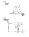
- FIG. 5 is a graph showing resonant frequency bands of sound generation sections a part of which are overlapped.
- FIG. 6 is a frequency characteristic chart relating to center frequencies and input reflection coefficients which sound generation section of a surface acoustic wave element configuring the stirring device of FIG. 4 .
- FIG. 7 is an equivalent circuit diagram of the surface acoustic wave element configuring the stirring device of FIG. 4 .
- FIG. 8 is an equivalent circuit figure in the case that the surface acoustic wave element in FIG. 7 is driven at the center frequency of one sound generation section.
- FIG. 9 is a partial cross sectional view of a reaction vessel for explaining sound waves which respective sound generation sections generate and an acoustic stream caused in a liquid sample by the sound waves in the case of FIG. 8 .
- FIG. 10 is an equivalent circuit diagram in the case that the surface acoustic wave element in FIG. 7 is driven at the center frequency of the other sound generation section.
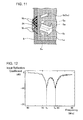
- FIG. 11 is a partial cross sectional view of a reaction vessel for explaining sound waves which respective sound generation sections generate and acoustic streams caused in a liquid sample by the sound waves in the case of FIG. 10 .
- FIG. 12 is a frequency characteristic chart showing an example of center frequencies and input reflection coefficients that two sound generation sections which a surface acoustic wave element comprises have.
- FIG. 13 is a profile visualizing flow speed distribution of acoustic streams generated in the case that respective sound generation sections having frequency characteristic shown in FIG. 12 are driven at respective center frequencies.
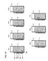
- FIG. 14 is a figure indicating acoustic streams caused in a liquid sample contained in a reaction vessel for respective drive frequencies when driving a surface acoustic wave element of FIG. 4 .
- FIG. 15 is a waveform figure showing an example of a drive signal for driving a surface acoustic wave element.
- FIG. 16 is a front elevation view showing a modified example of a surface acoustic wave element configured stirring device.
- FIG. 17 is an equivalent circuit diagram of the surface acoustic wave element shown in FIG. 16 .
- FIG. 18 is a frequency characteristic chart relating to center frequencies and input reflection coefficients which a sound generation section of a surface acoustic wave element shown in FIG. 16 has.
- FIG. 19 is a figure indicating acoustic streams caused in a liquid sample contained in a reaction vessel for respective drive frequencies when driving a surface acoustic wave element as shown in FIG. 16 .
- FIG. 20 is a front elevation view showing a modified example of a surface acoustic wave element as shown in FIG. 16 .
- FIG. 21 is an equivalent circuit diagram of a surface acoustic wave element as shown in FIG. 20 .
- FIG. 22 is a figure indicating acoustic streams caused in a liquid sample retained in a reaction vessel for respective drive frequencies when driving a surface acoustic wave element as shown in FIG. 20 .
- FIG. 23 is a front elevation view showing another modified example of a surface acoustic wave element as shown in FIG. 16 .
- FIG. 24 is an equivalent circuit diagram of a surface acoustic wave element as shown in FIG. 23 .
- FIG. 25 is a figure indicating acoustic streams caused in a liquid sample contained in a reaction vessel for respective drive frequencies when driving a surface acoustic wave element as shown in FIG. 23 .
- FIG. 26 is a perspective view depicting another mounting arrangement for mounting a surface acoustic wave element to a reaction vessel.
- FIG. 27 is a perspective view depicting yet another mounting arrangement for mounting a surface acoustic wave element to a reaction vessel.
- FIG. 28 is a perspective view depicting amounting arrangement for mounting a surface acoustic wave element on the bottom surface of a reaction vessel.
- FIG. 29 is a perspective view depicting amounting arrangement for mounting a surface acoustic wave element which also serves as a bottom surface of the reaction vessel.
- FIG. 1 is a skeleton configuration diagram of an automatic analyzing device comprising a stirring device.
- FIG. 2 is a perspective view depicting an enlarged portion A of a cuvette wheel configuring the automatic analyzing device shown in FIG. 1 , and a part of an enlarged portion A is depicted with cross section.
- FIG. 3 is a cross sectional plan view which horizontally cuts the cuvette wheel containing a reaction vessel at the position of a wheel electrode.
- FIG. 4 is a block diagram depicting a skeleton configuration of a stirring device with perspective view of a reaction vessel.
- the automatic analyzing device 1 comprises reagent tables 2 and 3 , a cuvette wheel 4 , an analyte vessel transfer mechanism 8 , analysis optical system 12 , a cleaning mechanism 13 , a control section 15 and a stirring device 20 as shown in FIG. 1 and FIG. 2 .
- the reagent tables 2 and 3 retain a plurality of reagent vessels 2 a and 3 a each located in a circumferential direction as shown in FIG. 1 and transfer the reagent vessels 2 a and 3 a in the circumferential direction rotated by a drive means.
- the cuvette wheel 4 has a plurality of holders 4 b formed in the circumferential direction for arranging a reaction vessel 5 by a plurality of partition plates 4 a which are formed in the circumferential direction, and the cuvette wheel 4 is rotated in the direction indicated with an arrow by a driving means (not shown) so as to convey the reaction vessel 5 .
- photometry holes 4 c are formed at the position of the cuvette wheel 4 corresponding to the lower part of the respective holders 4 b in the radius direction.
- Wheel electrodes 4 e are mounted by utilizing each of two vertically arranged insertion holes 4 d formed above the photometry holes 4 c . As shown in FIG. 2 and FIG.
- one end of the wheel electrode 4 e extending from the insertion hole 4 d is bent to be in contact with the outer face of the cuvette wheel 4 , while the other end extending from the insertion hole 4 d is bent to be arranged in the vicinity of the inner face of the holder 4 b , thereby holding the reaction vessel 5 arranged in the holder 4 b with a spring force.
- a reagent is dispensed into the reaction vessel 5 from the reagent vessels 2 a and 3 a of the reagent tables 2 and 3 by the reagent dispensing mechanisms 6 and 7 arranged in the vicinity.
- the reagent dispensing mechanisms 6 and 7 comprise probes 6 b and 7 b that dispense the reagent to arms 6 a and 7 a that pivot in the horizontal plane in the direction shown by an arrow, and have cleaning means for cleaning the probes 6 b and 7 b with cleaning water.
- the reaction vessel 5 is made of an optically transparent material. As shown in FIG. 2 , the reaction vessel 5 is a cuvette having a square cylindrical shape and having an opening 5 a in the upper portion. A surface acoustic wave element 24 is mounted at the sidewall 5 b of the reaction vessel 5 as a sound wave generation means and electrode pads 5 e that are connected to a set of input terminals 24 e of the surface acoustic wave element 24 are mounted on the reaction vessel.
- the reaction vessel 5 is made of a material that transmits 80% or more of light of the analytical light emitted from an analysis optical system 12 which will be described later, for example, a glass containing a heat-resistant glass, a synthetic resin such as ring olefin or polystyrene and the like are used.
- the portion of the reaction vessel 5 encircled by a dotted line at the lower part thereof adjacent to the portion where the surface acoustic wave element 24 is mounted is used as a window 5 c for photometry which allows the analytical light to transmit.
- the reaction vessel 5 is used, and the reaction vessel 5 is set to the holder 4 b with the surface acoustic wave element 24 facing the partition plate 4 a .
- each of the electrode pads 5 e of the reaction vessel 5 contacts with the corresponding wheel electrode 4 e .
- the electrode pads 5 e are configured to be integral with the surface acoustic wave element 24 .
- the analyte vessel transfer mechanism 8 is transfer means for transferring, one by one, a plurality of racks 10 arranged to a feeder 9 along the direction indicated by the arrow, wherein the racks 10 are transferred as advanced step by step.
- the rack 10 holds a plurality of analyte vessels 10 a containing an analyte. Every time the advance of the rack 10 transferred by the analyte vessel transfer mechanism 8 is stopped, the analyte is dispensed into respective reaction vessels 5 by an analyte dispensing mechanism 11 having an arm 11 a that is horizontally pivoted and a probe 11 b . Therefore, the analyte dispensing mechanism 11 has cleaning means for cleaning the probe 11 b with cleaning water.
- the analysis optical system 12 emits an analytical light for analyzing the liquid sample in the reaction vessel 5 , obtained by the reaction of the reagent and the analyte.
- the analysis optical system 12 has a light-emitting section 12 a , a spectroscopy section 12 b , and a light-receiving section 12 c .
- the analytical light emitted from the light-emitting section 12 a transmits the liquid sample in the reaction vessel 5 and is received by the light-receiving section 12 c provided at the position opposite to the spectroscopy section 12 b .
- the light-receiving section 12 c is connected to the control section 15 .
- the cleaning mechanism 13 sucks the liquid sample in the reaction vessel 5 with a nozzle 13 a for discharging the same, and then, repeatedly injects and sucks cleaning liquid such as a detergent or cleaning water by the nozzle 13 a , whereby the reaction vessel 5 in which the analysis by the analysis optical system 12 is completed is cleaned.
- the control section 15 controls the operation of each section of the automatic analyzing device 1 , and analyzes the component or concentration of the analyte based on the absorbance of the liquid sample in the reaction vessel 5 according to the quantity of the light emitted from the light-emitting section 12 a and the quantity of the light received by the light-receiving section 12 c .
- a microcomputer or the like is used for the control section 15 .
- the control unit 15 is connected to an input section 16 and a display section 17 as shown in FIG. 1 .
- the input section 16 is a portion for inputting inspection items and the like to the control section 15 .
- a keyboard or mouse and the like are used for the input section 16 .
- the input section 16 is also used for the operation of switching the frequency of a drive signal input to the surface acoustic wave element 24 of the stirring device 20 .
- the display section 17 displays the content of the analysis or alarm. A display panel and the like are used for the display unit 17 .
- the stirring device 20 has the drive control section 21 and the surface acoustic wave element 24 as a sound wave generation means.
- the drive control section 21 is a drive control section that changes the frequency of the drive signal input to the surface acoustic wave element 24 based on the information input from the input section 16 via the control section 15 , such as analysis items of the liquid, properties or amounts of the liquid and the like, to switch the position of a sound generation section which generates a sound wave.
- the drive control section 21 controls the frequency of drive signal within resonant frequency bands common to a plurality of sound generation sections 24 b and 24 c so that they simultaneously generate sound waves with different frequencies.
- the drive control section 21 is arranged so as to face the cuvette wheel 4 at the outer periphery of the cuvette wheel 4 (refer to FIG. 1 ) and has a brush-like contactor 21 b (refer to FIG.
- the contactor 21 b is provided at the housing 21 a opposite to the two wheel electrodes 4 e , wherein the contactor 21 a contacts with the wheel electrodes 4 e when the cuvette wheel 4 stops, so that the drive control section 21 and the surface acoustic wave element 24 of the reaction vessel 5 are electrically connected.
- the signal generator 22 has an oscillation circuit that can change the oscillation frequency based on the control signal input from the drive control circuit 23 , and inputs a high-frequency drive signal of several MHz to several hundred MHz to the surface acoustic wave element 24 .
- Electronic control means ECU having a memory and a timer incorporated therein is used for the drive control circuit 23 .
- the drive control circuit 23 controls the operation of the signal generator 22 based on the control signal input from the input section 16 via the control section 15 , thereby controlling the voltage or current of the drive signal output to the surface acoustic wave element 24 from the signal generator 22 .
- the drive control circuit 23 controls, for example, the characteristic (frequency, intensity, phase, characteristic of a wave), waveform (sine wave, triangular wave, rectangular wave, burst wave and the like), modulation (amplitude modulation, frequency modulation), or the like of the sound wave emitted from the surface acoustic wave element 24 by controlling the operation of the signal generator 22 .
- the drive control circuit 23 can vary the frequency of the high-frequency signal oscillated by the signal generator 22 in accordance with the incorporated timer.
- the surface acoustic wave element 24 has sound generation sections 24 b and 24 c spaced apart, which are composed of comb-shaped electrodes (IDT) 240 b and 240 c , on the surface of a piezoelectric substrate 24 a , and the sound generation sections 24 b and 24 c and a set of input terminals 24 e are connected by the bus bar 24 f .
- the surface acoustic wave element 24 is attached to the sidewall 5 b of the reaction vessel 5 via an acoustic matching layer such as epoxy resin or the like with a longitudinal direction of the piezoelectric substrate 24 a directed to a longitudinal direction of the sidewall 5 b .
- the sound generation sections 24 b and 24 c convert a drive signal input from the drive control section 21 to a surface acoustic wave (sound wave).
- the input terminals 24 e of the surface acoustic wave element 24 are connected to single drive control section 21 by the contactor 21 b which contacts to the wheel electrodes 4 e.
- a part of resonant frequency band of the sound generation section 24 b and 24 c are overlapped. That is, as shown in FIG. 5 , a center frequency of a fundamental wave of the sound generation section 24 b is fc 1 and a center frequency of a fundamental wave of the sound generation section 24 c is fc 2 (fc 1 ⁇ fc 2 ) (MHz), and when defining a resonant frequency band with a half-width ⁇ fc 1 or ⁇ fc 2 at which a response intensity value of ⁇ 3 dB of response intensity of oscillation for electrical input signal at respective center frequencies, part of the resonant frequencies are overlapped.
- the sound generation sections 24 b and 24 c have frequency characteristics separately shown with dotted line in FIG. 6 , and a solid line shows a frequency characteristic in combination of the two frequency characteristics. Furthermore, the sound generation sections 24 b and 24 c are formed so that origins of acoustic stream are arranged alternately. Regarding this point, it is described later.
- the piezoelectric substrate 24 a for example, the crystal of lithium niobate (LiNbO3) of Y cut Z propagation (YZ) can be used.
- the sound generation sections 24 b and 24 c are formed on the piezoelectric substrate 24 a in conjunction with input terminals 24 e or bus bar 24 f by the photolithography technology.
- the surface acoustic wave element 24 may be attached to the reaction vessel 5 in separable/contactable manner via an acoustic matching layer such as liquid or gel and the like.
- an acoustic matching layer such as liquid or gel and the like.
- the reagent dispensing mechanisms 6 and 7 successively dispense the reagent from the reagent vessels 2 a and 3 a into the plurality of reaction vessels 5 conveyed along the circumferential direction by the rotating cuvette wheel 4 .
- the analyte is successively dispensed by the analyte dispensing mechanism 11 from the plurality of analyte vessels 10 a retained at the rack 10 into the reaction vessels 5 to which the reagent has been dispensed. Consequently, every time the cuvette wheel 4 stops, the contactor 21 b contacts with the wheel electrode 4 e , so that the drive control section 21 and the surface acoustic wave element 24 of the reaction vessel 5 are electrically connected. Therefore, the dispensed reagent and the analyte in the reaction vessel 5 are successively stirred to be reacted by the stirring device 20 .
- the amount of the analyte is generally smaller than the amount of the reagent; therefore, the analyte in a small amount dispensed into the reaction vessel 5 are caught by the reagent in a large amount due to a series of flow caused by the stirring in the liquid, whereby the reaction of the analyte and the reagent is accelerated.
- the reaction solution obtained by the reaction of the analyte and the reagent as described above passes through the analysis optical system 12 when the cuvette wheel 4 rotates again, and as shown in FIG. 4 , a light beam LB emitted from the light-emitting section 12 a transmits the reaction solution.
- reaction solution of the reagent and the analyte in the reaction vessel 5 is subject to photometry by the light-receiving section 12 c , whereby the component, concentration or the like is analyzed by the control section 15 . Then the reaction vessel 5 after completing the analysis is cleaned by the cleaning mechanism 13 , and used again for the analysis of the analyte.
- the drive control section 21 inputs the drive signal to the input terminals 24 e via the contactor 21 b based on the control signal previously input from the input section 16 via the control unit 15 , when the cuvette wheel 4 stops.
- the sound generation section 24 b or the sound generation section 24 c of the surface acoustic wave element 24 is driven in accordance with the frequency of the input drive signal so as to induce a surface acoustic wave (bulk wave).
- the induced surface acoustic wave (bulk wave) is propagated from the acoustic matching layer into the sidewall 5 b of the reaction vessel 5 , and leaks into the liquid sample an acoustic impedance of which is close to that of the surface acoustic wave.
- two streams toward the diagonally upward direction and toward the diagonally downward direction with the origin corresponding to the sound generation section 24 b or the sound generation section 24 c in the liquid sample are produced in the reaction vessel 5 , whereby the dispensed reagent and the analyte are stirred by these two streams.
- the surface acoustic wave element 24 is designed such that the electric impedance at the center frequency of the respective sound generation sections 24 b and 24 c are set to 50 ohms that is the same as the electric impedance of an external electric system.
- the equivalent circuit of the surface acoustic wave element 24 is as shown in FIG. 7 with the impedances of the sound generation sections 24 b and 24 c defined as Z 1 and Z 2 respectively.
- the sound generation section 24 b of the surface acoustic wave element 24 is strongly excited, while the sound generation section 24 c of the surface acoustic wave element 24 is weakly excited.
- the sound wave generated by the excited sound wave generation sections 24 b and 24 c is propagated on the piezoelectric substrate 24 a and the side wall 5 b of the reaction vessel 5 so as to be mode-converted to a longitudinal wave at solid-liquid interface between the side wall 5 b and the liquid sample Ls contained in the reaction vessel 5 , then emitted into the liquid sample Ls.
- An acoustic stream is generated as the emitted longitudinal wave propagates in the liquid sample.
- the sound generation sections 24 b and 24 c are formed so as to alternately arrange the origins of acoustic stream, and the acoustic stream due to the sound wave W 1 generated by the excited sound generation section 24 b is expressed as S 11 and the acoustic stream due to the sound wave W 2 generated by the excited sound generation section 24 c is expressed as S 12 .
- the acoustic stream S 11 which is produced toward the diagonally upward direction in the liquid sample Ls of the acoustic stream S 11 due to the sound wave W 1 generated by the excited sound generation section 24 b is produced at a location interleaved with two acoustic streams S 12 produced toward the diagonally upward direction and toward the diagonally downward direction in the liquid sample Ls due to the sound wave W 2 generated by the excited sound generation section 24 c . Due to the above, two acoustic streams S 12 are integrated with the acoustic stream S 11 caused toward the diagonally upward right direction to form an acoustic stream S 1 with large cross section and high flow speed.
- the sound generation sections 24 b and 24 c are formed so as to alternately arrange the origins of the acoustic streams, as shown in FIG. 11 , the acoustic stream S 22 which is produced toward the diagonally downward right direction in the liquid sample Ls of the acoustic stream S 22 due to the sound wave W 2 generated by the sound generation section 24 c is produced at a location interleaved with two acoustic streams S 21 produced toward the diagonally upward right direction and toward the diagonally downward left direction in the liquid sample Ls due to the sound wave W 1 generated by the excited sound generation section 24 b .
- two acoustic streams S 21 are integrated with the acoustic stream S 22 produced toward the diagonally downward right direction to form an acoustic stream.
- S 3 with large cross section area and high flow speed. While the acoustic stream S 22 produced toward the diagonally upward right direction in the liquid sample Ls due to the sound wave W 2 generated by the excited sound generation section 24 c is an independent flow which has smaller cross section area and lower flow speed compared with the acoustic stream S 3 .
- ion exchanged water contained in the reaction vessel 5 was stirred by using the stirring device 20 with the surface acoustic wave element 24 having sound generation sections 24 b , 24 c of the frequency characteristic shown in FIG. 12 relating to center frequencies fc 1 and fc 2 and input reflection coefficient (dB).
- PIV is Particle Image Velocimetry, and generally, it is a method which adds an imaging process and an image analysis technology to a visualizing technology that makes visible a stream by adding markers such as tracers into an invisible stream to obtain simultaneous and multi-point velocity information of flow field.
- the electric impedance of an external electric system is other value, for example 70 ohms
- the electric impedance at the center frequencies of the sound generation sections 24 b and 24 c may be designed to be 70 ohms.
- the automatic analyzing device 1 creates a combination of the drive frequency and the analyte and the reagent at which stirring becomes best, combination of the drive frequency and the amount of the liquid or combination thereof to store in the control section 15 by initially making a survey of stirring condition for a different drive frequency with a combination of the analyte and the reagent. Then, the control section 15 automatically selects the drive frequency of the stirring device 20 from the combination of an analyte and a reagent included in the analysis information input from a host computer and the like to output to the drive control circuit 23 . Thereby the stirring device 20 can drive the surface acoustic wave element 24 with an optimized frequency for the combination of the analyte and the reagent.
- the automatic analyzing device 1 switches a drive frequency of the drive signal which drives the surface acoustic wave element 24 by the drive control circuit 21 , for example when the amount of the liquid sample retained in the reaction vessel 5 is small, to input the drive signal with frequency f 1 to the surface acoustic wave element 24 .
- the sound generation section 24 b of the surface acoustic wave element 24 of the stirring device 20 is weakly excited and the liquid sample is effectively stirred while suppressing energy consumption.
- the automatic analyzer 1 inputs the drive signal with the frequency fc 1 or the frequency fc 2 to the surface acoustic wave element 24 .
- the sound generation section 24 b or the sound generation section 24 c of the surface acoustic wave element 24 of the stirring device 20 is strongly excited.
- asymmetric acoustic streams S 1 and S 2 or acoustic streams S 3 and S 4 produce a stirring stream which largely rotates within the whole liquid sample Ls to stir the whole liquid sample Ls.
- the stirring device 20 controls the drive frequency F within frequency band (f 1 to f 3 ) by the drive control section 21 so that the plurality of sound generation sections 24 b and 24 c simultaneously generate sound waves with different frequencies, to always drive one or more sound generation section to stir the liquid sample Ls retained in the reaction vessel 5 according to the amount of the liquid sample Ls. Therefore, since patterns of the generated acoustic streams become diversified compared to the conventional stirring device with surface acoustic wave elements in which resonant frequencies are not overlapped, which can increase stirring efficiency to reduce time required for stirring.
- the stirring device 20 may alternately vary the frequency of the drive signal input to the surface acoustic wave element 24 , as shown in FIG. 15 , within the stirring time Ts in a time-sharing manner between the frequency fc 1 and the frequency fc 2 .
- the asymmetric acoustic streams S 1 and S 2 and the asymmetric acoustic streams S 3 and S 4 are alternately produced in the liquid sample Ls retained in the reaction vessel 5 to produce a stirring stream on a gas-liquid interface in addition to the bottom of the vessel; thereby the whole liquid sample Ls is stirred.
- the switching time of the frequencies fc 1 and fc 2 is not always set to 1:1. It may be appropriately changed according to the property of the liquid sample Ls such as viscosity or the amount of the liquid and the like.
- the position of the sound generation section 24 b and the sound generation section 24 c of the surface acoustic wave element 24 may be exchanged.
- the surface acoustic wave element 24 can produce acoustic stream which has different distribution from that of the acoustic stream shown in FIG. 14 .
- a sound generation section 24 d with the center frequency fc 3 (fc 1 ⁇ fc 2 ⁇ fc 3 ) (MHz) may be connected in parallel in addition to the sound generation sections 24 b and 24 c with the respective center frequencies fc 1 and fc 2 .
- electric impedances of the sound generation sections 24 b , 24 c and 24 d of the surface acoustic wave element 24 at respective center frequencies are designed to become 50 ohms which is the same as that of the external electric system.
- the equivalent circuit of the surface acoustic wave element 24 is as shown in FIG. 17 with the impedances of the sound generation sections 24 b , 24 c and 24 d being defined as Z 1 Z 2 and Z 3 respectively.
- the sound generation sections 24 b , 24 c and 24 d have frequency characteristics separately shown with dotted lines in FIG. 6 , and a solid line shows a frequency characteristic in combination of three frequency characteristics.
- the adjacent sound generation sections 24 b , 24 c and the adjacent sound generation sections 24 c , 24 d of the surface acoustic wave element 24 are formed so that origins of acoustic streams are arranged alternately.
- the stirring device 20 can generate various acoustic streams in the liquid sample retained in the reaction vessel 5 by changing frequencies as appropriate to drive the surface acoustic wave element 24 , the liquid sample is effectively stirred according to the amount of liquid while suppressing excess energy consumption thereby reducing time required for a stirring.
- the sound generation section 24 d may be located between the sound generation section 24 b and the sound generation section 24 c of the surface acoustic wave element 24 .
- the equivalent circuit of the surface acoustic wave element 24 is depicted in FIG. 21 , where Z 1 , Z 2 and Z 3 indicate the electric impedances of the sound generation sections 24 b , 24 c and 24 d , respectively.
- the acoustic streams produced in the liquid sample Ls are further varied by changing the arrangement of the sound generation sections 24 b , 24 c and 24 d .
- the stirring device 20 can effectively stir the liquid sample according to the amount of the liquid while suppressing excess energy consumption thereby reducing time required for a stirring.
- the sound generation section 24 b may be located between the sound generation section 24 c and the sound generation section 24 d of the surface acoustic wave element 24 .
- the equivalent circuit of the surface acoustic wave element 24 is depicted in FIG. 24 , where Z 1 , Z 2 and Z 3 indicate the electric impedances of the sound generation sections 24 b , 24 c and 24 d , respectively.
- the drive frequency F may be slid and varied between frequencies f 1 and f 3 in the stirring time
- the drive frequency F may be slid and varied between frequencies f 1 and f 4 in the stirring time.
- the various surface acoustic wave elements 24 as explained above may be mounted on the sidewall 5 b of the reaction vessel 5 with a longitudinal direction of the piezoelectric substrate 24 a directed to the width direction of the sidewall 5 b as shown in FIG. 26 .
- the stirring device 20 can produce different acoustic streams including horizontal flow for each drive frequency. Therefore, as shown in FIG. 27 , when the various surface acoustic wave elements 24 as explained above are mounted on the side wall 5 b of the reaction vessel 5 with a longitudinal direction of the piezoelectric substrate 24 a tilting against the width direction of the side wall 5 b , different acoustic streams including a horizontal direction component and a vertical direction component for each drive frequency can be produced.
- the various surface acoustic wave elements 24 as explained above may be mounted on the bottom face of the reaction vessel 5 .
- the surface acoustic wave element 24 can be mounted with the longitudinal direction of the piezoelectric substrate 24 a being directed to various directions taking the direction of the acoustic streams to be generated into account.
- reaction vessel to which various surface acoustic wave elements 24 as explained above is mounted may be cylindrical shape instead of the square cylindrical shaped reaction vessel 5 .
- the various surface acoustic wave elements 24 as described above may be driven wirelessly and the liquid sample retained in the reaction vessel 5 may be stirred using surface acoustic wave in addition to bulk wave.
- the surface acoustic wave element 24 may serve as the bottom face of the reaction vessel 5 .
- a plurality of sound generation sections are formed on a single piezoelectric substrate 24 a ; however, these sound generation sections are not required to be formed on the single piezoelectric substrate 24 a , instead, they may be formed so far as a plurality of the sound generation sections are electrically connected in parallel, and center frequencies of respective fundamental waves of sound generation sections differ from each other, respective resonant frequency bands of the sound generation section are partially overlapped with each other, and origins of acoustic streams caused by sound wave radiated to the vessel from different sound generation section are located alternately.
- shape or arrangement (dimension, location and the like) of a plurality of sound generation sections may be optimized as appropriate.
- the stirring device and the analyzing device of the present invention are useful to reduce time required for stirring, especially suitable for increasing stirring efficiency per time unit.
Landscapes
- Chemical & Material Sciences (AREA)
- Chemical Kinetics & Catalysis (AREA)
- Biochemistry (AREA)
- Health & Medical Sciences (AREA)
- Life Sciences & Earth Sciences (AREA)
- Analytical Chemistry (AREA)
- Physics & Mathematics (AREA)
- General Health & Medical Sciences (AREA)
- General Physics & Mathematics (AREA)
- Immunology (AREA)
- Pathology (AREA)
- Automatic Analysis And Handling Materials Therefor (AREA)
- Sampling And Sample Adjustment (AREA)
Applications Claiming Priority (3)
| Application Number | Priority Date | Filing Date | Title |
|---|---|---|---|
| JP2008259084A JP5274188B2 (ja) | 2008-10-03 | 2008-10-03 | 攪拌装置及び分析装置 |
| JP2008-259084 | 2008-10-03 | ||
| PCT/JP2009/055632 WO2010038494A1 (fr) | 2008-10-03 | 2009-03-23 | Agitateur et analyseur |
Publications (2)
| Publication Number | Publication Date |
|---|---|
| US20110176964A1 US20110176964A1 (en) | 2011-07-21 |
| US8668875B2 true US8668875B2 (en) | 2014-03-11 |
Family
ID=42073270
Family Applications (1)
| Application Number | Title | Priority Date | Filing Date |
|---|---|---|---|
| US13/122,384 Expired - Fee Related US8668875B2 (en) | 2008-10-03 | 2009-03-23 | Stirring device and an analyzing device |
Country Status (5)
| Country | Link |
|---|---|
| US (1) | US8668875B2 (fr) |
| EP (1) | EP2333562B1 (fr) |
| JP (1) | JP5274188B2 (fr) |
| CN (1) | CN102308218B (fr) |
| WO (1) | WO2010038494A1 (fr) |
Families Citing this family (9)
| Publication number | Priority date | Publication date | Assignee | Title |
|---|---|---|---|---|
| JP6318177B2 (ja) | 2013-02-11 | 2018-04-25 | アンドリュー イー. ブロック | 非対称振動をもたらすための装置 |
| JP6696732B2 (ja) * | 2015-04-22 | 2020-05-20 | オーソ・クリニカル・ダイアグノスティックス株式会社 | 検出又は定量方法及び装置 |
| JP6684545B2 (ja) * | 2015-04-22 | 2020-04-22 | オーソ・クリニカル・ダイアグノスティックス株式会社 | 検出又は定量方法、共振性添加剤、共振性構造体の使用方法及び容器 |
| JP7061525B2 (ja) * | 2018-06-29 | 2022-04-28 | 株式会社日立ハイテク | 化学分析装置 |
| US11577241B2 (en) * | 2018-12-03 | 2023-02-14 | Duke University | Acoustofluidic systems including acoustic wave generators for manipulating fluids, droplets, and micro/nano objects within a fluid suspension and related methods |
| EP3708247A1 (fr) * | 2019-03-14 | 2020-09-16 | Nederlandse Organisatie voor toegepast- natuurwetenschappelijk Onderzoek TNO | Mélange non invasif de liquides |
| JP6876764B2 (ja) * | 2019-09-24 | 2021-05-26 | オーソ・クリニカル・ダイアグノスティックス株式会社 | 検出又は定量方法、共振性添加剤、共振性構造体の使用方法及び容器 |
| JP2023097912A (ja) * | 2021-12-28 | 2023-07-10 | 株式会社日立ハイテク | 化学分析装置、化学分析方法 |
| WO2025255286A1 (fr) * | 2024-06-07 | 2025-12-11 | Siemens Healthcare Diagnostics Inc. | Mélange de réactif et d'échantillon à l'aide d'une excitation ultrasonore en mode ballottement |
Citations (3)
| Publication number | Priority date | Publication date | Assignee | Title |
|---|---|---|---|---|
| EP1340535A1 (fr) | 2002-03-01 | 2003-09-03 | Hitachi High-Technologies Corporation | Appareil et procédé d'analyse chimique |
| WO2007043261A1 (fr) | 2005-10-14 | 2007-04-19 | Olympus Corporation | Dispositif de brassage, contenant et dispositif d'analyse |
| JP2007108062A (ja) | 2005-10-14 | 2007-04-26 | Olympus Corp | 攪拌装置、容器及び分析装置 |
Family Cites Families (1)
| Publication number | Priority date | Publication date | Assignee | Title |
|---|---|---|---|---|
| US5983944A (en) * | 1998-03-20 | 1999-11-16 | Niv; Shaul E. | Apparatus for active fluid control |
-
2008
- 2008-10-03 JP JP2008259084A patent/JP5274188B2/ja not_active Expired - Fee Related
-
2009
- 2009-03-23 CN CN200980147113.1A patent/CN102308218B/zh not_active Expired - Fee Related
- 2009-03-23 US US13/122,384 patent/US8668875B2/en not_active Expired - Fee Related
- 2009-03-23 EP EP09817533.4A patent/EP2333562B1/fr not_active Not-in-force
- 2009-03-23 WO PCT/JP2009/055632 patent/WO2010038494A1/fr not_active Ceased
Patent Citations (6)
| Publication number | Priority date | Publication date | Assignee | Title |
|---|---|---|---|---|
| EP1340535A1 (fr) | 2002-03-01 | 2003-09-03 | Hitachi High-Technologies Corporation | Appareil et procédé d'analyse chimique |
| US20030166260A1 (en) * | 2002-03-01 | 2003-09-04 | Hajime Katou | Chemical analysis apparatus and chemical analysis method |
| JP2003254981A (ja) | 2002-03-01 | 2003-09-10 | Hitachi High-Technologies Corp | 化学分析装置及び化学分析方法 |
| WO2007043261A1 (fr) | 2005-10-14 | 2007-04-19 | Olympus Corporation | Dispositif de brassage, contenant et dispositif d'analyse |
| JP2007108062A (ja) | 2005-10-14 | 2007-04-26 | Olympus Corp | 攪拌装置、容器及び分析装置 |
| EP1947462A1 (fr) | 2005-10-14 | 2008-07-23 | Olympus Corporation | Dispositif de brassage, contenant et dispositif d'analyse |
Also Published As
| Publication number | Publication date |
|---|---|
| US20110176964A1 (en) | 2011-07-21 |
| CN102308218A (zh) | 2012-01-04 |
| EP2333562B1 (fr) | 2018-11-21 |
| WO2010038494A1 (fr) | 2010-04-08 |
| JP5274188B2 (ja) | 2013-08-28 |
| CN102308218B (zh) | 2014-12-17 |
| EP2333562A1 (fr) | 2011-06-15 |
| EP2333562A4 (fr) | 2014-01-08 |
| JP2010091306A (ja) | 2010-04-22 |
Similar Documents
| Publication | Publication Date | Title |
|---|---|---|
| US8668875B2 (en) | Stirring device and an analyzing device | |
| US7808631B2 (en) | Stirrer and analyzer | |
| US20100122586A1 (en) | Automatic analyzer and dispensing method | |
| US20080225634A1 (en) | Stirring vessel, stirring method, stirrer, and analyzer provided with stirrer | |
| US20090074621A1 (en) | Stirrer and analyzer | |
| US20080240992A1 (en) | Stirrer,vessel, and analyzer | |
| EP1912072A1 (fr) | Dispositif de melange et dispositif d'analyse equipe de ce dispositif de melange | |
| US20080240995A1 (en) | Reaction vessel and analyzer | |
| JP2007108061A (ja) | 攪拌装置、容器及び分析装置 | |
| JP2007108062A (ja) | 攪拌装置、容器及び分析装置 | |
| JP2009002918A (ja) | 音波発生体、攪拌装置及び自動分析装置 | |
| JP5219461B2 (ja) | 攪拌判定方法及び分析装置 | |
| JP2009014412A (ja) | 音波発生部材、容器および分析装置 | |
| HK1120612A (en) | Stirring device, container, and analysis device | |
| JP2007071736A (ja) | 攪拌装置及び攪拌装置を備えた分析装置 | |
| JP4861879B2 (ja) | 容器および分析装置 | |
| JP2007205816A (ja) | 分析装置と分析装置の測光方法 | |
| JP2007232523A (ja) | 攪拌装置と分析装置 | |
| JP2008292314A (ja) | 攪拌装置及び自動分析装置 | |
| JP2007232521A (ja) | 攪拌装置と分析装置 | |
| JP2007225449A (ja) | 表面弾性波素子及び反応容器 | |
| JP2008170379A (ja) | 攪拌装置及び自動分析装置 | |
| JP2007205814A (ja) | 分析装置と分析装置で用いる容器 | |
| JP2007232376A (ja) | 攪拌装置と分析装置 | |
| JP2009053113A (ja) | 洗浄装置及び自動分析装置 |
Legal Events
| Date | Code | Title | Description |
|---|---|---|---|
| AS | Assignment |
Owner name: BECKMAN COULTER, INC., CALIFORNIA Free format text: ASSIGNMENT OF ASSIGNORS INTEREST;ASSIGNOR:MURAKAMI, MIYUKI;REEL/FRAME:026063/0706 Effective date: 20110301 |
|
| STCF | Information on status: patent grant |
Free format text: PATENTED CASE |
|
| MAFP | Maintenance fee payment |
Free format text: PAYMENT OF MAINTENANCE FEE, 4TH YEAR, LARGE ENTITY (ORIGINAL EVENT CODE: M1551) Year of fee payment: 4 |
|
| FEPP | Fee payment procedure |
Free format text: MAINTENANCE FEE REMINDER MAILED (ORIGINAL EVENT CODE: REM.); ENTITY STATUS OF PATENT OWNER: LARGE ENTITY |
|
| LAPS | Lapse for failure to pay maintenance fees |
Free format text: PATENT EXPIRED FOR FAILURE TO PAY MAINTENANCE FEES (ORIGINAL EVENT CODE: EXP.); ENTITY STATUS OF PATENT OWNER: LARGE ENTITY |
|
| STCH | Information on status: patent discontinuation |
Free format text: PATENT EXPIRED DUE TO NONPAYMENT OF MAINTENANCE FEES UNDER 37 CFR 1.362 |
|
| FP | Lapsed due to failure to pay maintenance fee |
Effective date: 20220311 |