US8734192B2 - Terminal having a clamping spring - Google Patents
Terminal having a clamping spring Download PDFInfo
- Publication number
- US8734192B2 US8734192B2 US13/377,517 US201013377517A US8734192B2 US 8734192 B2 US8734192 B2 US 8734192B2 US 201013377517 A US201013377517 A US 201013377517A US 8734192 B2 US8734192 B2 US 8734192B2
- Authority
- US
- United States
- Prior art keywords
- screw
- terminal
- clamping spring
- clamping
- electrical conductor
- Prior art date
- Legal status (The legal status is an assumption and is not a legal conclusion. Google has not performed a legal analysis and makes no representation as to the accuracy of the status listed.)
- Expired - Fee Related, expires
Links
- 239000004020 conductor Substances 0.000 claims abstract description 48
- 235000001674 Agaricus brunnescens Nutrition 0.000 claims description 3
- 230000007935 neutral effect Effects 0.000 description 9
- 230000008878 coupling Effects 0.000 description 8
- 238000010168 coupling process Methods 0.000 description 8
- 238000005859 coupling reaction Methods 0.000 description 8
- 230000008901 benefit Effects 0.000 description 6
- 238000000034 method Methods 0.000 description 6
- 230000009471 action Effects 0.000 description 3
- 238000010616 electrical installation Methods 0.000 description 3
- 239000000463 material Substances 0.000 description 3
- 230000008569 process Effects 0.000 description 3
- 230000000694 effects Effects 0.000 description 2
- 230000006872 improvement Effects 0.000 description 2
- 239000003550 marker Substances 0.000 description 2
- 230000007704 transition Effects 0.000 description 2
- RYGMFSIKBFXOCR-UHFFFAOYSA-N Copper Chemical compound [Cu] RYGMFSIKBFXOCR-UHFFFAOYSA-N 0.000 description 1
- 229910052802 copper Inorganic materials 0.000 description 1
- 239000010949 copper Substances 0.000 description 1
- 238000010586 diagram Methods 0.000 description 1
- 238000006073 displacement reaction Methods 0.000 description 1
- 238000005516 engineering process Methods 0.000 description 1
- 238000004519 manufacturing process Methods 0.000 description 1
- 230000007246 mechanism Effects 0.000 description 1
- 230000036316 preload Effects 0.000 description 1
- 238000006467 substitution reaction Methods 0.000 description 1
Images




Classifications
-
- H—ELECTRICITY
- H01—ELECTRIC ELEMENTS
- H01R—ELECTRICALLY-CONDUCTIVE CONNECTIONS; STRUCTURAL ASSOCIATIONS OF A PLURALITY OF MUTUALLY-INSULATED ELECTRICAL CONNECTING ELEMENTS; COUPLING DEVICES; CURRENT COLLECTORS
- H01R4/00—Electrically-conductive connections between two or more conductive members in direct contact, i.e. touching one another; Means for effecting or maintaining such contact; Electrically-conductive connections having two or more spaced connecting locations for conductors and using contact members penetrating insulation
- H01R4/28—Clamped connections, spring connections
- H01R4/48—Clamped connections, spring connections utilising a spring, clip, or other resilient member
- H01R4/489—Clamped connections, spring connections utilising a spring, clip, or other resilient member spring force increased by screw, cam, wedge, or other fastening means
-
- H—ELECTRICITY
- H01—ELECTRIC ELEMENTS
- H01R—ELECTRICALLY-CONDUCTIVE CONNECTIONS; STRUCTURAL ASSOCIATIONS OF A PLURALITY OF MUTUALLY-INSULATED ELECTRICAL CONNECTING ELEMENTS; COUPLING DEVICES; CURRENT COLLECTORS
- H01R4/00—Electrically-conductive connections between two or more conductive members in direct contact, i.e. touching one another; Means for effecting or maintaining such contact; Electrically-conductive connections having two or more spaced connecting locations for conductors and using contact members penetrating insulation
- H01R4/28—Clamped connections, spring connections
- H01R4/48—Clamped connections, spring connections utilising a spring, clip, or other resilient member
- H01R4/4809—Clamped connections, spring connections utilising a spring, clip, or other resilient member using a leaf spring to bias the conductor toward the busbar
- H01R4/4811—Spring details
- H01R4/4816—Spring details the spring shape preventing insertion of the conductor end when the spring is unbiased
-
- H—ELECTRICITY
- H01—ELECTRIC ELEMENTS
- H01R—ELECTRICALLY-CONDUCTIVE CONNECTIONS; STRUCTURAL ASSOCIATIONS OF A PLURALITY OF MUTUALLY-INSULATED ELECTRICAL CONNECTING ELEMENTS; COUPLING DEVICES; CURRENT COLLECTORS
- H01R4/00—Electrically-conductive connections between two or more conductive members in direct contact, i.e. touching one another; Means for effecting or maintaining such contact; Electrically-conductive connections having two or more spaced connecting locations for conductors and using contact members penetrating insulation
- H01R4/28—Clamped connections, spring connections
- H01R4/48—Clamped connections, spring connections utilising a spring, clip, or other resilient member
- H01R4/4809—Clamped connections, spring connections utilising a spring, clip, or other resilient member using a leaf spring to bias the conductor toward the busbar
- H01R4/484—Spring housing details
- H01R4/4842—Spring housing details the spring housing being provided with a single opening for insertion of a spring-activating tool
Definitions
- the invention relates to connector terminals and, more particularly, to a terminal for at least one electrical conductor, where the terminal comprises a terminal base and a clamping spring applying a clamping force applied by to clamp the electrical conductor to the terminal base.
- Terminals are used in a multiplicity of different electrical devices and systems, as well as generally for electrical installation purposes.
- a clamping force is applied by a clamping spring.
- the clamping of an electrical conductor is accomplished, for example, in that a clamping edge clamps a bared end of the electrical conductor against the terminal base, as shown in a known terminal depicted in FIG. 1 . Hope, the clamping edge is disposed on the clamping spring itself. Normally, the clamping action is effected such that the inserted end of the electrical conductor causes the clamping edge bearing on the terminal base to move back.
- the spring can also be tensioned by an auxiliary tool, e.g., a screwdriver.
- an opening is provided in a housing of the terminal through which the auxiliary tool is introduced, and in the process acts on the clamping spring. In this way, it is also possible to release a clamped electrical conductor once more.
- a disadvantage with these generic terminals is a lower level of clamping reliability than in the case of screw-type terminals, i.e., with terminal contacts which are exposed to vibrations or other mechanical influences.
- the clamping force exerted by the clamping spring is often not enough to permanently clamp an electrical conductor permanently with a low contact resistance against the terminal base.
- a high level of clamping reliability to avoid system outages is required, particularly in the field of automation technology comprising extensive electrical installations such as the wiring of power supplies in switching cabinets, for example.
- the automobile industry stipulates that only screw-type terminals should be used in switching cabinets for car production plants.
- a clamping device with, a clamping spring, and a clamping device with a clamping screw are provided in a housing.
- An electrical conductor is initially clamped to a terminal base by a clamping spring.
- the electrical conductor can also be clamped against the terminal base by a clamping screw.
- a disadvantageous aspect therein is the amount of space that must be provided for the two clamping devices.
- It is therefore an object of the invention is to provide an improved terminal for an electrical conductor.
- a terminal in which a clamping spring is provided that applies a clamping force to clamp an electrical conductor namely to a base of the terminal.
- a screw is provided which is coupled to a support element and by which at least a section of the clamping spring is movable relative to the terminal base.
- the clamping spring itself is used to adjust the clamping force exerted by it by means of the screw.
- force applied to the clamping spring by the screw intensifies (increases) the clamping force effected by the preloading of the clamping spring, i.e., additional pressure is applied to the clamped conductor by the screw and in the process the conductor is pressed more firmly against the terminal base.
- the screw is guided through a housing of the terminal and the head of the screw is accessible from outside the housing.
- Screws disposed inside a housing are suitable for varying the spring preload of terminals of per se identical design. With the externally accessible screw, there is furthermore the possibility of increasing the clamping force in an already clamping state.
- a substantially rigid section of the clamping spring that transmits the clamping force onto the electrical conductor is movable relative to the terminal base by the screw.
- the terminal then acts in respect of clamping reliability like a conventional screw-type terminal in that the force applied by the screw is transmitted onto a substantially rigid clamping leg of the clamping spring.
- the clamping leg directly or indirectly clamps the electrical conductor tight by a rigid intermediate element.
- the force applied by the screw can also act directly on the intermediate element, where the clamping spring is also movable relative to the terminal base by the intermediate element.
- the thread of the screw engages with a thread of the clamping spring and that the screw head is supported on the support element of the terminal. Tightening the screw causes the movable clamping spring section to move in the direction of the terminal base, thereby intensifying (increasing) the clamping force acting on the electrical conductor. With the screw loosened, i.e., with a screw raised away from the support element, the clamping spring section remains freely movable and the terminal functions as a conventional spring clamp terminal.
- the screw has one end coupled to the clamping spring and the thread of the screw engages with a thread of the support element of the terminal.
- the clamping spring is implemented in a simple manner without a thread.
- the coupling has an axial play between screw and clamping spring, in this case, such that the clamping spring can move freely in the region of the axial play.
- the end of the screw bears on the clamping spring.
- the axial play is simply achieved by loosening the screw, i.e., by raising the screw a sufficient distance from the clamping spring.
- the screw is coupled to the clamping spring at a point that requires a tensile force from the screw onto the clamping spring in order to increase the clamping force, then the end is formed as a mushroom shape and guided in a groove-shaped recess of the clamping spring.
- the advantage is that the screw can also be used for loosening the clamping.
- the coupling of the screw to the clamping spring possesses a play in the axial direction of the screw. A region for screw positions with a freely movable clamping spring is then provided between the tightening of the screw in one direction of rotation to apply a tensile force and the tightening of the screw in the other direction of rotation to apply a compressive force.
- the screw is mounted rotatably in the support element and the thread of the screw engages with a thread of an intermediate element coupled to the clamping spring.
- This causes no displacement of the screw head in the axial direction, as a result of which only the height of the screw head needs to be taken into account with regard to the height of an insulating collar around the screw head.
- the coupling of the clamping spring to the intermediate element is provided with an axial play to allow free movement of the clamping spring. It is also possible to implement the coupling the between clamping spring and the intermediate element without axial play and to provide the necessary axial play in the mounting of the screw in the support element.
- a cover is movable together with the intermediate element, which cover, when subjected to the clamping force intensified (increase) by the screw, covers an opening in the housing provided for introducing a tool for tensioning the clamping spring and consequently for releasing the electrical conductor.
- the cover prevents the housing opening from being accessible to a screwdriver for releasing the clamping spring when the clamping spring is fixed by a screw. Inadvertent loosening attempts could lead to the terminal being damaged.
- inadvertent loosening attempts can be prevented in that fixing of the clamping spring by a screw is indicated by a mechanical element moved by means of the screw.
- a cage which encloses the clamping spring is beneficially provided as the intermediate element.
- the cage is therein configured such that, at a neutral screw position, the clamping spring is able to move freely within the cage.
- the cage has two resilient bars and a connecting brace having the thread and if the free ends of the bars have extensions that partially grip around the clamping spring.
- the two resilient bars can then be spread apart by a tool so that the distance between the extensions becomes greater than the width of the clamping spring, thereby enabling the clamping spring to be moved out of the cage.
- an intermediate element which comprises a sleeve having an internal thread, where the sleeve is guided in a recess of the clamping spring.
- the axial guide between the sleeve and the clamping spring has end stops where, an axial play is provided to enable a free movement of the clamping spring at a neutral screw position.
- a two-part screw is implemented such that the screw has an inner core on which a sleeve having an external thread is co-rotatably disposed and the external thread engages with an internal thread of the clamping spring.
- the sleeve and the inner core have an axial play.
- the clamping spring can move freely at a neutral position of the screw. When the screw is turned, the sleeve moves axially as far as a stop of the core, as a result of which a force is exerted onto the clamping spring.
- the support element is connected to the screw such that the support element is implemented as part of the housing in which the terminal base is affixed.
- the support element is held in the housing in which the terminal base is affixed.
- the support element then comprises, for example, a sleeve made of a material of higher strength than the strength of the housing material.
- terminal base and the support element are formed as a single piece.
- FIG. 1 shows a terminal having a clamping spring in accordance with the prior art
- FIG. 2 shows a terminal having a clamping spring and axially moved screw with an internal thread in the clamping spring in accordance with the invention
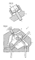
- FIG. 3 shows a mechanical indicator of the screw position in accordance with the invention
- FIG. 4 shows a terminal having a clamping spring and axially moved screw with an internal thread in the support element in accordance with the invention
- FIG. 5 shows a terminal having a clamping spring and axially fixed screw in accordance with the invention
- FIGS. 6-7 show a section A-A in accordance with the invention
- FIG. 5 at different screw positions
- FIG. 9 shows a terminal in accordance with the invention
- FIG. 5 with a cover
- FIG. 10 shows a section A-A in accordance with the invention
- FIG. 5 with a spreadable cage
- FIG. 11 shows view B in accordance with FIG. 10 ;
- FIG. 12 shows a terminal having a clamping spring and an axially moved screw exerting compressive force action onto the clamping spring in accordance with the invention.
- FIG. 13 shows a terminal having a clamping spring, axially moved screw and wedge-shaped intermediate element in accordance with the invention.
- a conventional terminal comprises a terminal base 2 and a clamping spring 3 which, in the absence of an electrical conductor 5 , bears on the terminal base 2 with a clamping edge.
- an electrical conductor 5 is clamped between the terminal base 2 and the clamping edge of the clamping spring 3 .
- the terminal base 2 and the clamping spring 3 are held in position relative to each other by a housing 4 .
- a clamping force is applied exclusively by the preloading of the clamping spring 3 .
- An opening 6 is disposed in the housing 4 to allow the clamping spring 3 to be tensioned or, as the case may be, a clamped electrical conductor 5 to be released.
- a screwdriver for example, can be introduced through the opening and the clamping spring tensioned.
- terminal depicted is an exemplary embodiment with the aid of which the invention is explained. Needless to say, the invention can also be applied to spring-type terminals of different design.
- FIG. 2 An embodiment of a terminal 1 in accordance with the invention is shown in FIG. 2 .
- a thread is incorporated in the clamping spring approximately at the point at which in known terminals a screwdriver starts to tension the clamping spring 3 .
- the thread of a screw 7 engages with the thread such that, as the screw is tightened, the clamping edge of the clamping spring 3 is moved in the direction of the terminal base 2 .
- the screw 7 is supported with the screw head against the housing 4 comprising a support element.
- the clamping spring 3 has a convexity 8 which is accessible through an opening 6 provided therefor in the housing 4 .
- the clamping spring 3 is shaped such that the section between the clamping edge and the thread is substantially rigid and the preloading is effected by a resilient deformation in another section. A high level of clamping reliability is ensured in this way, because the force applied by the screw is transmitted by the rigid section of the clamping spring 3 onto the clamping edge without a spring-loaded coupling.
- a tensioning of the clamping spring 8 or, as the case may be, releasing of the terminal 1 through the opening 6 provided therefor is possible only with the screw 7 loosened.
- the screw 7 is provided toward that end, for example, with a mechanical indicator element 15 that has a marked area that is only visible when the screw 7 is loosened. A loosened state of the screw is therefore indicated by the visible marker.
- the indicator element 15 is implemented, e.g., as a plastic sleeve that sheaths the screw head and moves in conjunction with the screw 7 in the axial direction.
- the screw head with the plastic sleeve is enclosed by a ring-shaped collar of the housing 4 such that the marked outer surface of the plastic sleeve is covered by the collar of the housing 4 when the screw 7 is tightened. Only when the screw 7 is loosened does the plastic sleeve protrude from the collar and signals by the outer lateral surface that is then visible that the terminal 1 can be released.
- the plastic sleeve affords the additional advantage that the screw 7 protruding from the housing collar continues to be protected against inadvertent contact.
- FIG. 4 Another embodiment of the invention is shown in FIG. 4 .
- the design of the terminal 1 is different from that shown in FIG. 2 in that the thread of the screw 7 engages with an internal thread of the housing 4 which comprising a support element.
- the thread is either formed in the housing 4 , which is usually made of plastic, or contained in a bushing which is incorporated into the housing 4 .
- the screw 7 is formed in a mushroom shape, i.e., the thread transitions into a thin section having a smaller diameter than the core diameter; an end section once more has a bigger diameter which is slightly smaller than the core diameter of the thread so that the screw can be screwed from outside into the housing.
- the end section is formed e.g. as a disk, sphere or similar.
- Embodied in the clamping spring 3 instead of a thread is a groove in which the mushroom-shaped end 9 is guided.
- the groove in this case, has a width that forms a clearance fit with the thin section of the mushroom-shaped end 9 .
- the groove has a widening through which the thicker end section of the mushroom-shaped end 9 is inserted during assembly.
- a plastic deformation of the mushroom-shaped end 9 after having been joined to the clamping spring 3 is possible.
- a sleeve having an internal thread is provided with which the thread of the screw engages, then on its outside the sleeve has a locking device to prevent it from being rotated relative to the housing in which it is held.
- the coupling between the mushroom-shaped end 9 of the screw 7 and the groove of the clamping spring 3 thus enables, on the one hand, a tensile force to be applied to the clamping spring 3 when the screw 7 is unscrewed from the housing 4 and, on the other hand, a compressive force to be applied to the clamping spring 3 when the screw 7 is screwed into the housing 4 .
- the length of the thin section of the mushroom-shaped end 9 is a neutral zone in which the screw 7 exerts no action on the clamping spring 3 . If the screw 7 is in such a position, the terminal 1 acts as a conventional spring clamp terminal.
- FIGS. 5-11 In order to prevent the screw 7 unscrewing from the housing during a clamping operation, a further modified embodiment is provided, as illustrated in FIGS. 5-11 .
- the clamping spring 3 has an aperture through which the screw 7 is inserted.
- the thread of the screw 7 engages with an internal thread of a cage 10 that encloses the clamping spring 3 .
- the screw 7 is rotatably mounted in the housing 4 by a cylindrical section.
- a corresponding bearing bushing can be provided in this case.
- Embodied in the axial direction on both sides of the cylindrical section are ring-shaped shoulders, which are braced on the inner or outer edge of the housing 4 according to the respective direction of rotation.
- the outer shoulder is beneficially formed by the screw head.
- the shoulder at the transition to the thread is disposed at a disk-shaped section 12 with increased diameter.
- the screw 7 is provided, for example, with a right-handed thread so that the cage 10 is pulled in the direction of the screw head when the screw 7 is turned in a clockwise direction.
- the cage 10 exerts a tensile force on the clamping spring 7 and thereby intensifies (increases) the clamping force.
- FIG. 6 Such a positional arrangement is shown in FIG. 6 .
- the clamping spring 3 is not in contact with the cage 10 in the sectional plane, but makes contact at the outer edges of the cage 10 due to the spring flexing effect.
- FIG. 8 A position in a neutral setting is shown in FIG. 8 .
- the clamping spring 3 can move freely within a range that is defined by the clearance of the cage 10 . This state is beneficially the condition in which the terminal 1 is shipped.
- the screw 7 can have a cylindrical core on which a sleeve having an external thread is disposed with an axial play.
- the thread of the sleeve is in engagement with an internal thread of the clamping spring 3 .
- a the cylindrical core and the sleeve of the screw 7 can in this case be displaced only axially and not radially relative to each other.
- the axial play determines the neutral zone in which the clamping spring 3 is free to move. Only when the sleeve is located against an axial stop is a turn of the screw transmitted onto the clamping spring 3 .
- the screw is screwed into a sleeve having an internal thread.
- the sleeve is co-rotatably guided in a recess of the clamping spring 3 .
- Arranged at the front faces of the sleeve are stops by which a compressive or tensile force can be applied to the clamping spring 2 .
- the height of the sleeve between the stops again defines the neutral zone in which the clamping spring 3 is freely movable.
- An electrical conductor 5 is clamped in that the screw 7 is initially turned in the anticlockwise direction.
- the cage 10 moves away from the screw head, tensioning the clamping spring 3 in the process.
- the clamping leg of the clamping spring 3 moves away from the terminal base 2 with the clamping edge formed by a brace at the end of the clamping leg and exposes a wire inlet for inserting the electrical conductor 5 .
- the convexity 8 of the clamping spring 3 can be pressed in the direction of the terminal base 2 by a screwdriver. If the clamping edge is configured in an appropriate manner, introducing the electrical conductor 5 can also cause the clamping spring 3 to move back.
- the electrical conductor 5 After the electrical conductor 5 has been inserted into the opening provided it is clamped in position by the clamping spring 3 . If the wire inlet was previously exposed by actuation of the screw 7 , the screw 7 must initially be turned in the clockwise direction into a neutral position for that purpose.
- the spring force is additionally intensified by the screw 7 and the electrical conductor 5 is pressed more firmly against the terminal base 2 .
- a high level of clamping reliability is established.
- a very high contact pressure is generated by the screw 7 being tightened. If the screw 7 should work loose as a result of material creep or extreme vibrations, then the clamping spring 3 still presses against the electrical conductor 5 with the full spring force.
- a further improvement provides that a cover 13 is moved in conjunction with the cage 10 .
- the cover 13 is pushed in front of the opening 6 for inserting the screwdriver when the clamping spring 3 is not freely movable and consequently also cannot be moved by a screwdriver by way of the convexity 8 of the clamping spring 3 . In this way, an erroneous actuation of the terminal 1 is avoided in this way.
- a further improvement comprising a spreadable cage 10 ′ is provided to enable the terminal 1 to be released in any case like a conventional spring clamp terminal.
- a cage is shown in FIG. 10 .
- the cage 10 ′ does not completely enclose the clamping spring 3 .
- the two lateral bars of the cage 10 ′ each have a free end, at which ends inward-projecting extensions are provided which also move the clamping spring 3 during a movement in the direction of the screw head.
- the cage 10 ′ is configured such that a screwdriver 14 introduced to tension the clamping spring 3 initially forces itself between the two lateral bars of the cage 10 ′ and presses these apart resiliently, as indicated by the arrows in FIG. 10 .
- This causes the distance between the two extensions of the free ends of the cage bars to be increased to such an extent that the clamping spring 3 can be pressed out of the cage 10 ′ by the screwdriver 14 and tensioned.
- the free ends of the cage bars each have an outward-pointing bevel such that the clamping spring 3 springing back into the cage 10 ′ itself presses apart the free ends of the cage bars.
- the terminal 1 can be tensioned or, as the case may be, released by the screwdriver 14 by way of the convexity 8 of the clamping spring 3 .
- FIG. 12 A further embodiment of the invention is shown in FIG. 12 .
- the screw 7 engages at the free end of the clamping leg of the clamping spring 3 .
- the free end is bent through a right angle and consequently represents a bearing surface for the screw 7 .
- the thread of the screw 7 engages with an internal thread of the housing 4 formed as a support element, and when the screw 7 is turned in the clockwise direction presses the free end of the clamping spring 4 and consequently the clamping edge against a tightly clamped electrical conductor 5 .
- the mechanism for tensioning or, as the case may be, releasing the clamping spring 3 by a screwdriver can be actuated when the screw 7 is loosened.
- the screw 7 is disposed in a different area.
- no separate convexity to act as a bearing surface for the screwdriver needs to be provided for the clamping spring 3 .
- FIG. 13 An embodiment offering better accessibility of the screw head is shown in FIG. 13 .
- the axis of the screw 7 is not aligned in the direction of the clamping force, but is approximately orthogonal thereto.
- the screw 7 has a cone-shaped tip 16 that bears on an angled section of the clamping leg of the clamping spring 3 .
- the screw diameter increases at the contact point between screw 7 and clamping spring 3 , thereby in turn effecting a movement of the clamping leg in the direction of the clamping force and intensifying the spring force accordingly.
- the screw 7 can act on an angled free end of the clamping leg or on a section of the terminal leg that lies between the clamping edge and the spring-loaded section of the clamping spring 3 .
- the screw head is again surrounded by a collar of the housing 4 .
Landscapes
- Connections Arranged To Contact A Plurality Of Conductors (AREA)
- Connections By Means Of Piercing Elements, Nuts, Or Screws (AREA)
Applications Claiming Priority (3)
| Application Number | Priority Date | Filing Date | Title |
|---|---|---|---|
| ATA899/2009 | 2009-06-10 | ||
| AT0089909A AT508278B1 (de) | 2009-06-10 | 2009-06-10 | Klemme mit einer klemmfeder |
| PCT/EP2010/055828 WO2010142494A1 (fr) | 2009-06-10 | 2010-04-29 | Connecteur à ressort de serrage |
Publications (2)
| Publication Number | Publication Date |
|---|---|
| US20120077391A1 US20120077391A1 (en) | 2012-03-29 |
| US8734192B2 true US8734192B2 (en) | 2014-05-27 |
Family
ID=42309645
Family Applications (1)
| Application Number | Title | Priority Date | Filing Date |
|---|---|---|---|
| US13/377,517 Expired - Fee Related US8734192B2 (en) | 2009-06-10 | 2010-04-29 | Terminal having a clamping spring |
Country Status (6)
| Country | Link |
|---|---|
| US (1) | US8734192B2 (fr) |
| EP (1) | EP2441127B1 (fr) |
| CN (1) | CN102460837B (fr) |
| AT (1) | AT508278B1 (fr) |
| RU (1) | RU2011150249A (fr) |
| WO (1) | WO2010142494A1 (fr) |
Cited By (3)
| Publication number | Priority date | Publication date | Assignee | Title |
|---|---|---|---|---|
| US20150093943A1 (en) * | 2013-10-01 | 2015-04-02 | Tyco Electronics Japan G.K. | Terminal Block |
| US20170373406A1 (en) * | 2016-06-23 | 2017-12-28 | Wago Verwaltungsgesellschaft Mbh | Contact insert of a spring force connection clamp and spring force connection clamp configured with said contact insert |
| US20220247122A1 (en) * | 2021-02-03 | 2022-08-04 | Wago Verwaltungsgesellschaft Mbh | Conductor terminal |
Families Citing this family (8)
| Publication number | Priority date | Publication date | Assignee | Title |
|---|---|---|---|---|
| DE102011081037A1 (de) * | 2011-08-16 | 2013-02-21 | Siemens Aktiengesellschaft | Anschlussklemme und Schutzschaltgerät |
| DE102012110759B4 (de) | 2012-11-09 | 2021-04-01 | Wago Verwaltungsgesellschaft Mbh | Federkraftklemmanschluss und elektrisches Gerät hiermit |
| NZ607726A (en) * | 2013-03-06 | 2014-09-26 | Gallagher Group Ltd | Securing device |
| DE102015100823B4 (de) * | 2015-01-21 | 2021-12-09 | Phoenix Contact Gmbh & Co. Kg | Elektrische Anschlussklemme |
| CN106329174B (zh) * | 2015-06-18 | 2024-05-10 | 连展科技电子(昆山)有限公司 | 壁挂架组件及其夹线型连接器 |
| DE202018101729U1 (de) * | 2018-03-28 | 2019-07-01 | Wago Verwaltungsgesellschaft Mbh | Leiteranschlussklemme, Klemmfeder einer Leiteranschlussklemme sowie Reihenklemme |
| US12046533B2 (en) * | 2019-06-25 | 2024-07-23 | Mitsubishi Electric Corporation | Semiconductor device |
| CN117525919B (zh) * | 2024-01-05 | 2024-03-19 | 深圳市华科精密组件有限公司 | 一种端子连接器 |
Citations (13)
| Publication number | Priority date | Publication date | Assignee | Title |
|---|---|---|---|---|
| CH552286A (de) | 1974-03-29 | 1974-07-31 | Woertz Fa | Elektrische klemme. |
| US3891297A (en) | 1974-04-10 | 1975-06-24 | Leviton Manufacturing Co | Electrical connector for attachment to multi-conductor cable |
| US6146187A (en) | 1998-11-25 | 2000-11-14 | Supplie & Co. Import/Export, Inc. | Screwless terminal block |
| DE10037550A1 (de) | 2000-08-02 | 2002-02-14 | Luetze Friedrich Elektro | Kabelanschlussvorrichtung |
| FR2819110A1 (fr) | 2001-01-02 | 2002-07-05 | Legrand Sa | Borne de connexion automatique |
| DE10205470C1 (de) | 2002-02-08 | 2003-08-14 | Wieland Electric Gmbh | Anschlusskontakt |
| US6689955B2 (en) * | 2001-09-20 | 2004-02-10 | Entrelec S.A. | Connecting device with a connection spring operated by a cam |
| US7097518B2 (en) * | 2004-05-04 | 2006-08-29 | Tyco Electronics Amp Gmbh | Contact terminal |
| US7179137B1 (en) * | 2005-08-18 | 2007-02-20 | Weidmüller Interface GmbH & Co. KG | Electrical connector arrangement |
| DE102005050267A1 (de) | 2005-10-20 | 2007-04-26 | Phoenix Contact Gmbh & Co. Kg | Reihenklemme |
| DE102007016333A1 (de) | 2007-04-04 | 2008-10-09 | Siemens Ag | Elektrisches Reiheneinbaugerät |
| EP2034562A2 (fr) | 2007-09-10 | 2009-03-11 | Lapp Engineering & Co | Connecteur à fiches doté d'un corps d'isolation en une pièce |
| US7651363B2 (en) * | 2007-05-11 | 2010-01-26 | Wago Verwaltungsgesellschaft Mbh | Terminal component |
Family Cites Families (5)
| Publication number | Priority date | Publication date | Assignee | Title |
|---|---|---|---|---|
| DE3302372A1 (de) * | 1983-01-25 | 1984-07-26 | WAGO Verwaltungsgesellschaft mbH, 4950 Minden | Schraubenlose klemme |
| DE3504317A1 (de) | 1985-02-08 | 1986-08-14 | Licentia Patent-Verwaltungs-Gmbh, 6000 Frankfurt | Klemme fuer elektrische leiter |
| DE29608178U1 (de) * | 1996-05-06 | 1996-07-25 | Weidmüller Interface GmbH & Co, 32760 Detmold | Zugfederanschluß mit einsteckbarem Anschlagelement |
| DE19629563A1 (de) * | 1996-07-15 | 1998-01-22 | Wago Verwaltungs Gmbh | Elektr. Klemme mit Überlastschutz |
| DE20308863U1 (de) * | 2003-06-06 | 2003-08-21 | Ria Btr Produktions Gmbh | Anschlussklemme |
-
2009
- 2009-06-10 AT AT0089909A patent/AT508278B1/de not_active IP Right Cessation
-
2010
- 2010-04-29 RU RU2011150249/02A patent/RU2011150249A/ru not_active Application Discontinuation
- 2010-04-29 US US13/377,517 patent/US8734192B2/en not_active Expired - Fee Related
- 2010-04-29 CN CN201080025760.8A patent/CN102460837B/zh not_active Expired - Fee Related
- 2010-04-29 WO PCT/EP2010/055828 patent/WO2010142494A1/fr not_active Ceased
- 2010-04-29 EP EP10718144.8A patent/EP2441127B1/fr not_active Not-in-force
Patent Citations (14)
| Publication number | Priority date | Publication date | Assignee | Title |
|---|---|---|---|---|
| CH552286A (de) | 1974-03-29 | 1974-07-31 | Woertz Fa | Elektrische klemme. |
| US3891297A (en) | 1974-04-10 | 1975-06-24 | Leviton Manufacturing Co | Electrical connector for attachment to multi-conductor cable |
| US6146187A (en) | 1998-11-25 | 2000-11-14 | Supplie & Co. Import/Export, Inc. | Screwless terminal block |
| DE10037550A1 (de) | 2000-08-02 | 2002-02-14 | Luetze Friedrich Elektro | Kabelanschlussvorrichtung |
| FR2819110A1 (fr) | 2001-01-02 | 2002-07-05 | Legrand Sa | Borne de connexion automatique |
| US6689955B2 (en) * | 2001-09-20 | 2004-02-10 | Entrelec S.A. | Connecting device with a connection spring operated by a cam |
| DE10205470C1 (de) | 2002-02-08 | 2003-08-14 | Wieland Electric Gmbh | Anschlusskontakt |
| US7097518B2 (en) * | 2004-05-04 | 2006-08-29 | Tyco Electronics Amp Gmbh | Contact terminal |
| US7179137B1 (en) * | 2005-08-18 | 2007-02-20 | Weidmüller Interface GmbH & Co. KG | Electrical connector arrangement |
| DE102005050267A1 (de) | 2005-10-20 | 2007-04-26 | Phoenix Contact Gmbh & Co. Kg | Reihenklemme |
| US20080233782A1 (en) | 2005-10-20 | 2008-09-25 | Phoenix Contact Gmbh & Co. Kg | Terminal Block |
| DE102007016333A1 (de) | 2007-04-04 | 2008-10-09 | Siemens Ag | Elektrisches Reiheneinbaugerät |
| US7651363B2 (en) * | 2007-05-11 | 2010-01-26 | Wago Verwaltungsgesellschaft Mbh | Terminal component |
| EP2034562A2 (fr) | 2007-09-10 | 2009-03-11 | Lapp Engineering & Co | Connecteur à fiches doté d'un corps d'isolation en une pièce |
Cited By (6)
| Publication number | Priority date | Publication date | Assignee | Title |
|---|---|---|---|---|
| US20150093943A1 (en) * | 2013-10-01 | 2015-04-02 | Tyco Electronics Japan G.K. | Terminal Block |
| US9252507B2 (en) * | 2013-10-01 | 2016-02-02 | Tyco Electronics Japan G.K. | Terminal block |
| US20170373406A1 (en) * | 2016-06-23 | 2017-12-28 | Wago Verwaltungsgesellschaft Mbh | Contact insert of a spring force connection clamp and spring force connection clamp configured with said contact insert |
| US10141661B2 (en) * | 2016-06-23 | 2018-11-27 | Wago Verwaltungsgesellschaft Mbh | Contact insert of a spring force connection clamp and spring force connection clamp configured with said contact insert |
| US20220247122A1 (en) * | 2021-02-03 | 2022-08-04 | Wago Verwaltungsgesellschaft Mbh | Conductor terminal |
| US11888276B2 (en) * | 2021-02-03 | 2024-01-30 | Wago Verwaltungsgesellschaft Mbh | Conductor terminal |
Also Published As
| Publication number | Publication date |
|---|---|
| AT508278B1 (de) | 2011-12-15 |
| US20120077391A1 (en) | 2012-03-29 |
| AT508278A1 (de) | 2010-12-15 |
| EP2441127A1 (fr) | 2012-04-18 |
| CN102460837A (zh) | 2012-05-16 |
| CN102460837B (zh) | 2015-03-25 |
| WO2010142494A1 (fr) | 2010-12-16 |
| EP2441127B1 (fr) | 2014-06-04 |
| RU2011150249A (ru) | 2013-06-20 |
Similar Documents
| Publication | Publication Date | Title |
|---|---|---|
| US20120077391A1 (en) | Terminal Having A Clamping Spring | |
| KR101257145B1 (ko) | 링 케이블 러그를 전기 기구에 접속하기 위한 터미널부 | |
| US6572419B2 (en) | Electrical connector | |
| EP2835878B1 (fr) | Vissage mural de boîtier pour un connecteur à fiche électrique | |
| EP2315313B1 (fr) | Ensemble pour la connexion multiple dans un appareil électrique | |
| US10211569B2 (en) | Connector device | |
| CN202221712U (zh) | 带有联接端子装置的安装开关设备 | |
| US20130316576A1 (en) | Connecting element | |
| US11764495B2 (en) | Protective conductor connection | |
| KR20150131006A (ko) | 삽입형 커넥터 | |
| JPH04264373A (ja) | 拘束ねじ端子および端子板 | |
| CN110896015B (zh) | 将电导体连接到电气设备的连接垫的端子和电气保护设备 | |
| JP3158734U (ja) | 同軸ケーブル用コネクタ | |
| JP2006516800A (ja) | リングケーブルシュー及び関連する電気装置を接続する接続端子装置 | |
| US8986054B2 (en) | Clamp body for terminal | |
| JP6095180B1 (ja) | コネクタ | |
| EP3940880A1 (fr) | Borne de batterie | |
| JP2008133900A (ja) | ネジの締結構造 | |
| WO2014182276A1 (fr) | Vis de serrage de fils de domino | |
| KR20230002960A (ko) | 스프링식 단자 부품, 전자 접촉기 및 과부하 계전기 | |
| CN220753870U (zh) | 连接器及其螺钉装置 | |
| US11811156B2 (en) | Battery pole terminal | |
| KR102674881B1 (ko) | 차단기용 너트체결식 단자연결구조 | |
| HK1086671A (en) | Connecting terminal device for connecting a ring cable shoe and associated electric device | |
| KR20180053737A (ko) | 전기 기기 |
Legal Events
| Date | Code | Title | Description |
|---|---|---|---|
| AS | Assignment |
Owner name: SIEMENS AKTIENGESELLSCHAFT, GERMANY Free format text: ASSIGNMENT OF ASSIGNORS INTEREST;ASSIGNORS:HE, XIAOYONG, DR.;SCHWEIGERT, HARALD;SIGNING DATES FROM 20111010 TO 20111012;REEL/FRAME:027355/0308 |
|
| STCF | Information on status: patent grant |
Free format text: PATENTED CASE |
|
| MAFP | Maintenance fee payment |
Free format text: PAYMENT OF MAINTENANCE FEE, 4TH YEAR, LARGE ENTITY (ORIGINAL EVENT CODE: M1551) Year of fee payment: 4 |
|
| FEPP | Fee payment procedure |
Free format text: MAINTENANCE FEE REMINDER MAILED (ORIGINAL EVENT CODE: REM.); ENTITY STATUS OF PATENT OWNER: LARGE ENTITY |
|
| LAPS | Lapse for failure to pay maintenance fees |
Free format text: PATENT EXPIRED FOR FAILURE TO PAY MAINTENANCE FEES (ORIGINAL EVENT CODE: EXP.); ENTITY STATUS OF PATENT OWNER: LARGE ENTITY |
|
| STCH | Information on status: patent discontinuation |
Free format text: PATENT EXPIRED DUE TO NONPAYMENT OF MAINTENANCE FEES UNDER 37 CFR 1.362 |
|
| FP | Lapsed due to failure to pay maintenance fee |
Effective date: 20220527 |