US8747464B2 - Device and system for assisting and/or taking over the pumping function of the heart - Google Patents
Device and system for assisting and/or taking over the pumping function of the heart Download PDFInfo
- Publication number
- US8747464B2 US8747464B2 US12/991,978 US99197809A US8747464B2 US 8747464 B2 US8747464 B2 US 8747464B2 US 99197809 A US99197809 A US 99197809A US 8747464 B2 US8747464 B2 US 8747464B2
- Authority
- US
- United States
- Prior art keywords
- heart
- sheathing
- base part
- sheathing part
- layer
- Prior art date
- Legal status (The legal status is an assumption and is not a legal conclusion. Google has not performed a legal analysis and makes no representation as to the accuracy of the status listed.)
- Expired - Fee Related, expires
Links
- 210000002216 heart Anatomy 0.000 title claims abstract description 185
- 238000005086 pumping Methods 0.000 title claims abstract description 21
- 230000006641 stabilisation Effects 0.000 claims abstract description 63
- 238000011105 stabilization Methods 0.000 claims abstract description 63
- 238000003780 insertion Methods 0.000 claims abstract description 54
- 230000037431 insertion Effects 0.000 claims abstract description 54
- 239000012530 fluid Substances 0.000 claims abstract description 40
- 230000003416 augmentation Effects 0.000 claims abstract description 27
- 125000004122 cyclic group Chemical group 0.000 claims abstract description 17
- 230000006835 compression Effects 0.000 claims abstract description 14
- 238000007906 compression Methods 0.000 claims abstract description 14
- 238000007493 shaping process Methods 0.000 claims abstract description 5
- 210000000038 chest Anatomy 0.000 claims description 40
- 239000007788 liquid Substances 0.000 claims description 28
- 230000001050 lubricating effect Effects 0.000 claims description 12
- 210000003516 pericardium Anatomy 0.000 claims description 10
- 241000722921 Tulipa gesneriana Species 0.000 claims description 3
- 239000007789 gas Substances 0.000 description 29
- 210000000115 thoracic cavity Anatomy 0.000 description 24
- 230000006870 function Effects 0.000 description 16
- 210000004379 membrane Anatomy 0.000 description 11
- 239000012528 membrane Substances 0.000 description 11
- 210000004072 lung Anatomy 0.000 description 10
- 210000000779 thoracic wall Anatomy 0.000 description 10
- 210000000056 organ Anatomy 0.000 description 9
- 239000000203 mixture Substances 0.000 description 8
- 230000000747 cardiac effect Effects 0.000 description 7
- 239000008246 gaseous mixture Substances 0.000 description 6
- 239000000499 gel Substances 0.000 description 6
- 210000001015 abdomen Anatomy 0.000 description 5
- 210000005240 left ventricle Anatomy 0.000 description 5
- 210000005241 right ventricle Anatomy 0.000 description 5
- 210000000683 abdominal cavity Anatomy 0.000 description 4
- 238000007599 discharging Methods 0.000 description 4
- 239000000463 material Substances 0.000 description 4
- 210000001519 tissue Anatomy 0.000 description 4
- 238000006243 chemical reaction Methods 0.000 description 3
- 230000006837 decompression Effects 0.000 description 3
- 230000004217 heart function Effects 0.000 description 3
- 230000002441 reversible effect Effects 0.000 description 3
- 210000001562 sternum Anatomy 0.000 description 3
- 210000002417 xiphoid bone Anatomy 0.000 description 3
- 206010000060 Abdominal distension Diseases 0.000 description 2
- 239000000853 adhesive Substances 0.000 description 2
- 238000004026 adhesive bonding Methods 0.000 description 2
- 230000001070 adhesive effect Effects 0.000 description 2
- 238000010009 beating Methods 0.000 description 2
- 230000001684 chronic effect Effects 0.000 description 2
- 230000006378 damage Effects 0.000 description 2
- 230000000694 effects Effects 0.000 description 2
- 238000003384 imaging method Methods 0.000 description 2
- 230000000451 tissue damage Effects 0.000 description 2
- 231100000827 tissue damage Toxicity 0.000 description 2
- 230000007704 transition Effects 0.000 description 2
- 206010007556 Cardiac failure acute Diseases 0.000 description 1
- 206010020772 Hypertension Diseases 0.000 description 1
- 208000019693 Lung disease Diseases 0.000 description 1
- 230000009471 action Effects 0.000 description 1
- 210000000709 aorta Anatomy 0.000 description 1
- 230000005540 biological transmission Effects 0.000 description 1
- 239000008280 blood Substances 0.000 description 1
- 210000004369 blood Anatomy 0.000 description 1
- 230000008602 contraction Effects 0.000 description 1
- 230000008878 coupling Effects 0.000 description 1
- 238000010168 coupling process Methods 0.000 description 1
- 238000005859 coupling reaction Methods 0.000 description 1
- 239000003814 drug Substances 0.000 description 1
- 229940079593 drug Drugs 0.000 description 1
- 230000001747 exhibiting effect Effects 0.000 description 1
- 108010025899 gelatin film Proteins 0.000 description 1
- 239000001307 helium Substances 0.000 description 1
- 229910052734 helium Inorganic materials 0.000 description 1
- SWQJXJOGLNCZEY-UHFFFAOYSA-N helium atom Chemical compound [He] SWQJXJOGLNCZEY-UHFFFAOYSA-N 0.000 description 1
- 230000001771 impaired effect Effects 0.000 description 1
- 238000002513 implantation Methods 0.000 description 1
- 230000005923 long-lasting effect Effects 0.000 description 1
- 238000004519 manufacturing process Methods 0.000 description 1
- 238000000034 method Methods 0.000 description 1
- 210000003205 muscle Anatomy 0.000 description 1
- 210000004165 myocardium Anatomy 0.000 description 1
- 230000035515 penetration Effects 0.000 description 1
- 210000001147 pulmonary artery Anatomy 0.000 description 1
- 230000001020 rhythmical effect Effects 0.000 description 1
- 238000004904 shortening Methods 0.000 description 1
- 230000000087 stabilizing effect Effects 0.000 description 1
- 238000004659 sterilization and disinfection Methods 0.000 description 1
- 239000000126 substance Substances 0.000 description 1
- 238000009736 wetting Methods 0.000 description 1
Images




Classifications
-
- A—HUMAN NECESSITIES
- A61—MEDICAL OR VETERINARY SCIENCE; HYGIENE
- A61M—DEVICES FOR INTRODUCING MEDIA INTO, OR ONTO, THE BODY; DEVICES FOR TRANSDUCING BODY MEDIA OR FOR TAKING MEDIA FROM THE BODY; DEVICES FOR PRODUCING OR ENDING SLEEP OR STUPOR
- A61M60/00—Blood pumps; Devices for mechanical circulatory actuation; Balloon pumps for circulatory assistance
- A61M60/10—Location thereof with respect to the patient's body
- A61M60/122—Implantable pumps or pumping devices, i.e. the blood being pumped inside the patient's body
- A61M60/165—Implantable pumps or pumping devices, i.e. the blood being pumped inside the patient's body implantable in, on, or around the heart
- A61M60/191—Implantable pumps or pumping devices, i.e. the blood being pumped inside the patient's body implantable in, on, or around the heart mechanically acting upon the outside of the patient's native heart, e.g. compressive structures placed around the heart
-
- A—HUMAN NECESSITIES
- A61—MEDICAL OR VETERINARY SCIENCE; HYGIENE
- A61M—DEVICES FOR INTRODUCING MEDIA INTO, OR ONTO, THE BODY; DEVICES FOR TRANSDUCING BODY MEDIA OR FOR TAKING MEDIA FROM THE BODY; DEVICES FOR PRODUCING OR ENDING SLEEP OR STUPOR
- A61M60/00—Blood pumps; Devices for mechanical circulatory actuation; Balloon pumps for circulatory assistance
- A61M60/20—Type thereof
- A61M60/289—Devices for mechanical circulatory actuation assisting the residual heart function by means mechanically acting upon the patient's native heart or blood vessel structure, e.g. direct cardiac compression [DCC] devices
-
- A—HUMAN NECESSITIES
- A61—MEDICAL OR VETERINARY SCIENCE; HYGIENE
- A61M—DEVICES FOR INTRODUCING MEDIA INTO, OR ONTO, THE BODY; DEVICES FOR TRANSDUCING BODY MEDIA OR FOR TAKING MEDIA FROM THE BODY; DEVICES FOR PRODUCING OR ENDING SLEEP OR STUPOR
- A61M60/00—Blood pumps; Devices for mechanical circulatory actuation; Balloon pumps for circulatory assistance
- A61M60/40—Details relating to driving
- A61M60/465—Details relating to driving for devices for mechanical circulatory actuation
- A61M60/468—Details relating to driving for devices for mechanical circulatory actuation the force acting on the actuation means being hydraulic or pneumatic
-
- A—HUMAN NECESSITIES
- A61—MEDICAL OR VETERINARY SCIENCE; HYGIENE
- A61M—DEVICES FOR INTRODUCING MEDIA INTO, OR ONTO, THE BODY; DEVICES FOR TRANSDUCING BODY MEDIA OR FOR TAKING MEDIA FROM THE BODY; DEVICES FOR PRODUCING OR ENDING SLEEP OR STUPOR
- A61M60/00—Blood pumps; Devices for mechanical circulatory actuation; Balloon pumps for circulatory assistance
- A61M60/80—Constructional details other than related to driving
- A61M60/855—Constructional details other than related to driving of implantable pumps or pumping devices
- A61M60/861—Connections or anchorings for connecting or anchoring pumps or pumping devices to parts of the patient's body
Definitions
- This invention relates to a device for assisting and/or taking over the pumping function of the heart, comprising a multilayer sheathing part configured for compressing the heart at least in certain sections, wherein the sheathing part has at least one stabilization layer for shaping the sheathing part, and at least one inner extensible augmentation layer, and wherein between the stabilization layer and the augmentation layer at least one cavity is formed, which is inflatable and deflatable by means of a fluid, for cyclic compression of the heart.
- a device for pericardially assisting and/or taking over the cardiac activity of the above-mentioned type is known, for instance, from the German Patent Application DE 199 51 220 A1.
- This is a not very invasive, i.e., percutaneously implantable system, for mechanically assisting and temporarily replacing the pumping function of the heart.
- the device After probing of the pericardium, the device is inserted percutaneously into the pericardium, or at the end of an operation is surgically positioned inside the pericardium, and placed therein with a double membrane around the right and left ventricle. In a deflated state of the double membrane, the device is so thin that compression of neighboring organs is avoided.
- the cavity of the double membrane is rhythmically loaded via a connecting tube with a fluid, which may be a gas (helium or CO 2 ) or some appropriate liquid. Due to this rhythmical inflating and deflating of the cavity of the double membrane, and because the outer membrane, in contrast to the inner membrane, is not extensible, pressure transmission and compression of the heart via the double membrane enclosing the heart occurs. In doing so, blood from the right ventricle is expelled into the pulmonary artery, and simultaneously, from the left ventricle into the aorta, or if a pumping function of the heart is present, the systolic ejection work of the cardiac muscle is assisted.
- a fluid which may be a gas (helium or CO 2 ) or some appropriate liquid.
- This device also provides a double membrane for epicardially assisting and/or taking over cardiac activity, having an elastic inner membrane and a non-elastic outer membrane, as well as a closed cavity formed therebetween, which is inflatable and deflatable by means of a fluid, with a first chamber assigned to the right ventricle and a second chamber assigned to the left ventricle.
- the first chamber and the second chamber are connected together via at least one valve inside a dividing wall separating both chambers.
- double membranes can be manufactured, which allow for the sole augmentation of the right ventricle, or—in another embodiment—of the left ventricle only, both while maintaining the possibility of assisting both ventricles simultaneously.
- the devices described above are fastened directly to the heart and to the organs surrounding the heart inside the thorax, so that the devices are constantly in direct contact with the heart surface.
- mounting and fixing the devices to the delicate tissue of the heart, lungs, and great vessels is only possible in a limited way because of the organs' macro and micro-anatomical nature. Frictional forces occurring between the device and tissue can at very short term, within hours and days, lead to considerable irreparable tissue damage; penetrations of the ventricles and great vessels inside the thorax will result in the patient's death within minutes.
- the intrinsic heart action may be hindered or affected, with the heart, due to the mechanical pumping function thereof, exhibiting cyclic shortening or lengthening of the heart axis with simultaneous spiral-like rotation about the heart axis.
- Another challenge for devices to be introduced inside the thorax is due to the spatial and positional relations between organs (heart, lung, great vessels) on the one hand, as well as between thoracic organs and the inner wall of the thorax on the other hand. They offer very limited possibilities for deploying instruments or devices introduced into the thorax at or around the heart or for bypassing the heart.
- the device is to be easily introduced and removed into and out of the thorax in a minimally invasive way, i.e., without conventional surgical opening of the thorax (thoracotomy).
- the structure and operating mode of the device are to allow for positionally true positioning within the thorax at or around the heart, without the risk of damage to the heart and/or surrounding organs.
- the stabilization layer is inflatable in certain sections by means of a fluid and deflatable by discharging the fluid, so as to convert the sheathing part through inflation of the stabilization layer from a coiled and/or collapsed insertion state during insertion of the device into the body into a curved functional state, wherein the heart in the functional state of the sheathing part is at least partially sheathed and/or encompassed by the sheathing part.
- the stabilization layer substantially completely encases or encompasses both ventricles of the heart.
- the inventive system has at, least one auxiliary device for allowing for minimally invasive introduction of the inventive device into the body.
- the invention is based on the fundamental idea of providing a device for assisting and/or taking over the pumping function of the heart, which can be deployed inside the thorax.
- the inventive device may be applied in a surgically not very invasive and not very complicated way, and allows for readily available adequate assistance of the pumping function of the heart, in particular in emergency situations, e.g., in case of acute heart failure with cardiac output of less than 50% up to complete loss of the mechanical cardiac function.
- the sheathing part may be uncoiled or unfolded via the inflatable and deflatable stabilization layer, with the heart and/or the heart inside the pericardium (pericard) being sheathed, encompassed, or enclosed by the sheathing part in the functional state.
- the stabilization layer is meant for ensuring sufficient rigidity or stability of the device implanted at or around the heart, as well as for conforming to the shape of the heart.
- the sheathing part can be collapsed or coiled up flexibly, a minimally invasive introduction of the device into the thorax and later removal without conventional surgical opening of the thorax is possible.
- the stabilization layer is provided for unfolding or uncoiling of the sheathing part and configured accordingly.
- the augmentation layer has significantly greater extensibility than the stabilization layer. If a gas or gaseous mixture is cyclically fed into the cavity between the stabilization layer and the augmentation layer, with correspondingly existing overpressure inside the cavity, inwardly directed bulging of the cavity is caused, which is meant for compression of the neighboring ventricles, as well as for cardiac massage and assistance of the cardiac function. It should be appreciated that alternatively also the augmentation layer as such may be inflatable.
- the sheathing part has a flare-like tulip shape adapted to the shape of the heart, with the heart, in the functional state of the sheathing part, being sheathed and/or encompassed from front to back over the lateral walls and, preferably, over the apex of the heart up to the region of the posterior walls of the heart.
- the stabilizing layer must be configured accordingly in order to ensure the conformation of the sheathing part by inflating or uncoiling and/or deploying during conversion from the insertion state into the functional state.
- the augmentation layer may be provided only in the region above the lateral walls of the heart and the posterior walls of the ventricles, so as to form the cavity for cyclically compressing and decompressing the heart in the region of the lateral walls and the posterior walls of the heart.
- it may also be provided for the inventive device to expose the apex of the heart or not to sheathe or encompass it.
- the rigidity of the sheathing part which is required for assisting and/or taking over the pumping function of the heart, is produced by feeding a gas or an appropriate liquid into inflatable regions of the stabilization layer.
- the sheathing part in the insertion state may comprise an inflatable edge portion, which is spirally coiled and/or folded from outside to inside.
- the edge region of the sheathing part may be uncoiled or deployed accordingly so as to obtain the conformation of the sheathing part to the shape of the heart.
- the sheathing part may be coiled or folded up starting from both longitudinal edges towards the middle of the sheathing part, so that the sheathing part can be coiled up or collapsed into a very small insertion size in the insertion state, thereby simplifying the minimally invasive introduction into the thoracic cavity and the later removal from the thoracic cavity without conventional surgical opening of the thorax.
- the sheathing part in the functional state, to have a preferably hyperbolic recess open towards the top for the great heart vessels on the backside, i.e., on the side facing the posterior walls of the heart.
- the inventive device comprises means enabling reversible fastening or fixation of the implanted device inside the thoracic cavity without the device being fastened at the heart as such or at the pericardium, lungs, or great vessels inside the thoracic cavity.
- at least one fastening means for heart and/or pericardium-free fastening of the sheathing part is provided, preferably for fastening to an inner wall of the thorax and/or to at least one rib of the patient.
- a fastening means preferably, a plurality of suction cups for suction on the inner wall of the thorax may be provided, so that the device may be fastened positionally true to the inner wall of the thorax above the heart. Due to heart and pericardium-free fastening of the sheathing part or the inventive device the mobility of the beating heart is not hindered in spite of assistance to the pumping function.
- fastening may also be implemented in the space between the ribs, by being supported through clamping or expansion at the surrounding ribs, or via two mutually screwed plates inside and outside the thorax.
- fastening at the breastbone and/or coastal arch by clamping, wedging, screw fitting or stitching is possible.
- percutaneous fastening may be provided, wherein the inventive device may have a distal end, which is fastened in the skin, e.g., by stitching, gluing, or clamping.
- fastening may be done via micro-hooks or adhesive members located on the device or by reversible gluing to the inner thoracic wall.
- fastening at the thoracic diaphragm is possible, wherein the inventive device may be supported with its distal end on this muscle plate and fastened by stitching, clamping, or hooking.
- a plurality of suction cups is provided as a fastening means, then they are connected to at least one fluid line for aspirating or discharging the aspiration spaces created between the suction cups and an inner wall of the thorax. Aspiration allows for the pressure in the aspiration spaces to be reduced, and thus for positionally true fastening of the inventive device above the heart at the inner wall of the thorax. Moreover, lubricating liquid may be supplied via the suction cups in order to obtain improved sliding properties.
- a non-inflatable base part connected to the sheathing part is provided, with the base part comprising the fastening means and, wherein preferably, the base part with respect to the arrangement in the functional state is extending in parallel to the heart axis from an upper edge of the sheathing part over the heart base to the bottom towards the apex of the heart.
- the base part is provided for fastening the device inside the thoracic cavity or for holding the sheathing part.
- Base part and sheathing part are preferably different components of different layer structure and/or different rigidity, which are solidly interconnected.
- the base part comprises as a holding member a plurality of suction cups, which are superficially arranged over the base part.
- micro-hooks or adhesive members may be provided in order to fasten the inventive device to the inner thoracic wall.
- a complete connection existing over the full length of the base part, may be provided.
- This connection between both parts is mainly meant for fixing the sheathing part via the base part at the inner wall of the thorax.
- the base part may rest with the full length thereof on the sheathing part, the connection between both parts being provided on the whole underside or at least part of the underside of the base part.
- the underside is supposed to be the side of the base part facing the heart. Basically, it is of course also possible for the base part to be only partially connected to the sheathing part, i.e., in certain sections over the length thereof.
- the base part may comprise at least one outer application layer configured for applying a lubricating liquid on the inner and/or outer side of the base part, with an inner channel system and pore-like orifices toward the inner side and/or outer side.
- the inner channel system is accordingly connected to at least one fluid line so as to discharge a lubricating liquid over the application layer. Discharging a lubricating liquid allows for possible frictional forces and tissue damage to be reduced. If the base part on the inner side thereof is applied directly to the surface of the heart, then discharging a lubricating liquid on the inner side may allow for the surface of the heart and the inner surface of the inventive device to slide on each other with minimal frictional forces occurring.
- the base part may have an elongated shape, with the length of the base part being preferably about 2 ⁇ 3 of the length of the front side of the sheathing part relating to the functional state. Thereby fastening of the base part to the inner thoracic wall is simplified.
- the base part is preferably configured elastically so that the base part adapts to the bulge of the inner wall when being fastened to the inner wall of the thorax.
- secure fastening of the base part is simplified, whereby for instance the suction cups provided for fastening of the base part to the inner wall may adhere to the inner wall on the whole surface.
- the base part in relation to the arrangement in the functional state is only connected to the sheathing part in the region between the upper edge of the sheathing part and the base of the heart.
- the sheathing part in relation to the insertion state is advantageous for the sheathing part in relation to the insertion state to have two coiled and/or folded inflatable edge portions extending in the longitudinal direction, with the base part being arranged between the edge portions, and with both edge portions converging into a common round-bottom-shaped edge portion for sheathing and/or encompassing the apex of the heart.
- Each coiled and/or folded edge portion extending in the longitudinal direction may in relation to the insertion state comprise a straight fastening portion for fastening to the base part, and a free portion following the straight fastening portion, curving away from the plane of the base part, and not being fastened to the base part, whereby the free portions arranged on both longitudinal sides of the base part converge at the round-bottom-shaped edge portion.
- the free portions are preferably articulated outwards and/or curved away from the plane of the base part with respect to the straight fastening portions.
- a recess for receiving and fastening the base part may be formed, thereby allowing for secure fastening of the base part to the sheathing part on the one hand, and a small size in the insertion state as well as the required conformation of the sheathing part, on the other hand.
- the stabilization layer may have a honeycomb structure with a plurality of adjacent honeycomb cells, with the honeycomb cells being connected to at least one fluid line for cyclically supplying a fluid into the honeycomb cells, with the honeycomb cells preferably having a cross-section tapering towards the heart with a larger base area on the side remote from the heart, and with a smaller base area on the side close to the heart, and wherein, if a fluid is supplied into the honeycomb cells, the honeycomb cells inflate, and an inward arching of the sheathing part is caused.
- the stabilization layer has a honeycomb-like structure and is not very or not at all extensible. When a compressed gas or gaseous mixture is filled into the honeycomb structure, a higher gas pressure is generated within the honeycomb cells.
- This higher gas pressure provides the inventive device implanted inside the thorax with the necessary shape (curvature) for sheathing or encompassing or encircling the heart.
- the overpressure within the honeycomb cells will provide the inventive device with the necessary rigidity, which is required for assisting or taking over the pumping function of the heart.
- the sheathing part comprises a stabilization layer with a corresponding honeycomb structure, which will lead to a simple constructive architecture of the inventive device and low manufacturing cost.
- a stabilization layer with honeycomb-like cells, with the layers overlapping completely or only partially, and possibly having a structure like a roof tile assembly.
- the stabilization layer preferably extends over the whole area of the sheathing part.
- the stabilization layer may extend over the area of the sheathing part in certain sections only.
- the sheathing part in the functional state may also encompass or grip the heart in a finger-like fashion only.
- At least one stabilization wire may be provided for the sheathing part, with the stabilization wire being arranged preferably between the stabilization layer and the augmentation layer.
- a stabilization wire starting from the base part of the device and placed at the posterior pole of the encompassing of the sheathing part around the apex of the heart may be provided, which may be provided as an additional stabilization support for the sheathing part and as an assisting member during the introduction of the inventive device into the body.
- the stabilization wire may allow for the lower region of the sheathing part to be pulled around the apex of the heart when the device is inserted. Thereby, a minimally invasive introduction of the inventive device into the body is simplified.
- At least one service layer connected with the stabilization layer for supplying a fluid into the honeycomb cells may be provided.
- servicing of the honeycomb cells with the fluid is done via three service or fluid lines separated from each other, whereby three neighboring honeycomb cells can be filled with fluid through different service performances. This ensures that even in case of leakage inside a honeycomb cell, no pressure loss may occur in a neighboring honeycomb cell, so that the rigidity and stability of the sheathing part is maintained even in case of leakage.
- the sheathing part may comprise at least one application layer configured for applying a lubricating liquid on the inner and/or outer side of the sheathing part, with an inner channel system and pore-like orifices towards the inner side and/or outer side of the functional part.
- the lubricating liquid reduces frictional forces between the inner surface of the sheathing part facing the surface of the heart and the surface of the heart during cyclic compression of the heart.
- a shifting gap between the surface of the heart and the inner surface of the inventive device is to be created, wherein inside this shifting gap or space for extracorporeal liquids, gels and/or drugs and/or other substances may be applied.
- the application of a lubricating liquid on the inner side and on the outer side of the sheathing part on the one hand, and of the base part on the other hand is provided, so that a direct contact fit between the inner surface of the inventive device and the heart, or the heart inside the pericardium, as well as the outer surface of the inventive device and the adjacent lungs is avoided.
- a direct contact fit between the inner surface of the inventive device with the heart and the outer surface of the device with the adjacent lung tissue may be completely prevented.
- the application layer preferably extends over the whole surface of the sheathing part.
- the sheathing part in the inventive device is formed by a stabilization layer, which is preferably fitted on both sides with an application layer, wherein in the region above the lateral walls of the heart and the posterior walls of the ventricles (relating to the functional state of the sheathing part), between the stabilization layer and the application layer, the augmentation layer is provided, so that in this region the cavity for cyclic compression of the heart may be configured.
- one or more electrodes may be mounted in order to integrate a pace-maker function into the device, or with at least two electrodes, to produce direct potentials for reproducing an ECG. If at least three electrodes are integrated into the device and spatially arranged, then three-dimensional ECG leads may be performed thereby.
- Imaging methods during the complete operation of insertion provide the treating physician with information on shapes, positional relations, and size of the organs inside the thoracic cavity before the introduction of the device, as well as during the insertion of the inventive device on the position of the auxiliary means introduced and the device within the body at the heart.
- the treating physician selects which embodiment and size may be implemented for the particular patient.
- he or she may then preferably make use of 4 basic forms of the device, which may comprise a selection of several secondary variants with different sized versions (small, medium, large, very large).
- the basic forms are:
- a spatula-like probing device which is part of the inventive system, may be advanced in the direction of the thoracic cavity up to the heart.
- the thoracic diaphragm diaphragma
- Larrey's cleft is located in the front area of the thoracic diaphragm.
- the spatula-like probing device After traversing the thoracic diaphragm, the spatula-like probing device is generally pivoted to the right (as seen by the inserting physician to the right into the left thoracic cavity side considering anatomical sides) in order to reach the apex of the heart.
- the spatula-like probing device When the heart is reached and probed, the spatula-like probing device is carefully pushed between the anterior wall of the heart and the inner thoracic wall. Possible adhesions of the pericardium and the inner thoracic wall may be detached bluntly with the spatula-liken probing device. After the anterior wall of the heart has been bypassed and possible adhesions have been bluntly detached, the probing device is removed from the body by withdrawal.
- a tube-like insertion device which is also part of the inventive system, is introduced through the access in the upper abdomen by the proximal end, and advanced up to the apex of the heart.
- a mobile positioning device forming another part of the inventive system, with the inventive device being fastened at the proximal end, is advanced through an insertion channel of the tube-like insertion device until the apex of the heart is reached.
- the insertion device is pulled back by several centimeters, so that a mobile joint protrudes at the proximal end of the positioning device into the thoracic cavity from the proximal end of the insertion device.
- Fluid inlet and outlet lines of the inventive device are connected to a fluid service and control device arranged outside of the body.
- the sheathing part is deployed around the heart by means of gas pressure, and the device is fixed to the inner thoracic wall by means of the suction inside the base part of the device.
- the mobile positioning device is removed from the body through the insertion channel of the insertion device.
- the tube-like insertion device is pulled out the body via the inlet and outlet lines, and may be split into two half-shells outside of the body and thus removed from the inlet and outlet lines of the inventive device.
- a liquid or liquid mixture or gel is applied to the inner and outer surface of the device through the respective application layer of the sheathing part.
- the wetting liquid film is supposed to create a shifting gap respectively between the inner surface of the device and the heart as well as the outer surface and the adjacent lungs in order to reduce frictional forces as far as possible.
- Cyclic pumping with a gas or gas mixture in the augmentation layer of the sheathing part may allow for direct assistance of the pumping function of the heart.
- the minimally invasive removal of the inventive device from the body includes the following process steps:
- the inventive device can be removed from the body, just like removing drainage from a body cavity, by pulling at the inlet or outlet lines.
- the passage point into the inside of the body at the upper abdomen is sutured after removal of the device.
- FIG. 1 shows a perspective representation of an inventive device for assisting and/or taking over the pumping function of the heart in the functional state of a sheathing part of the device;
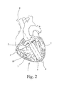
- FIG. 2 shows the device represented in FIG. 1 in the functional state during cyclic compression and decompression of the heart in a front view;
- FIG. 3 shows the device represented in FIG. 1 in the functional state during cyclic compression and decompression of the heart in a lateral view
- FIG. 4 shows the device represented in FIG. 1 in the collapsed insertion state in a top view
- FIG. 5 a cross-sectional view of the inventive device taken along line I-I in FIG. 4 ;
- FIG. 6 shows the device represented in FIG. 4 in a lateral view
- FIG. 7 shows the device represented in FIG. 1 in a cross-sectional view in the functional state of the sheathing part
- FIG. 8 shows a schematic representation of the layer structure of the sheathing part of the device represented in FIG. 1 in the deflated insertion state of the sheathing part;
- FIG. 9 shows a plan view on a base part of the device represented in FIG. 1 ;
- FIG. 10 shows a schematic representation of a suction cup on the base part represented in FIG. 9 for fastening the base part to an inner wall of the thorax;
- FIG. 11 shows the base part represented in FIG. 9 in a schematic representation in the state aspirated against an inner wall of the thorax;
- FIG. 12 shows a schematic cross-sectional view of a stabilization layer of the sheathing part of the device represented in FIG. 1 in the functional state of the sheathing part;
- FIG. 13 shows a schematic representation of the stabilization layer represented in FIG. 12 having a honeycomb-like structure
- FIGS. 14 a & 14 b show, respectively, a plan view and a perspective view of an application layer of the device represented in FIG. 1 for application of a lubricating liquid;
- FIG. 15 shows a schematic cross-sectional view of a positioning device for positioning the device represented in FIG. 1 ;
- FIGS. 16 a & 16 b show a head joint of the positioning device represented in FIG. 15 , respectively, in the state coupled with the base part represented in FIG. 9 and in the decoupled state;
- FIG. 17 shows a spatula-shaped probing device
- FIGS. 18 a - 18 c show a tubular multipart insertion device for inserting the device represented in FIG. 1 into the thoracic cavity in the insertion state of the sheathing part in a cross-sectional view, a longitudinal sectional view, and a plan view, respectively;
- FIG. 19 shows a schematic view of the device represented in FIG. 1 with a stabilization wire for the sheathing part
- FIG. 20 shows a schematic representation of the fixation of the base part represented in FIG. 9 to the ribs of the thorax.
- FIG. 1 a device 1 for assisting and/or taking over the pumping function of a heart 2 (shown FIGS. 2 and 3 ) which has a multilayer sheathing part 3 , the sheathing part 3 being configured for compressing the heart, and the sheathing part 3 comprising a stabilization layer 4 (represented in FIGS. 7 , 8 , and 12 ) for shaping the sheathing part 3 .
- the sheathing part 3 comprises an inner extensible augmentation layer 5 , (represented in FIGS. 7 and 8 ).
- At least one cavity 6 (represented in the inflated state in FIG. 7 ) is formed between the stabilization layer 4 and the augmentation layer 5 , cavity 6 being inflatable by means of a fluid and then deflated for cyclic compression of the heart 2 .
- the stabilization layer 4 is inflatable by means of a fluid, at least in certain sections, in order to convert the sheathing part 3 from a coiled and/or collapsed insertion state of the device 1 (represented for instance in FIG. 4 ) that allows for insertion of the device 1 into the body, into an arched functional state (represented in FIG. 1 ).
- the heart 2 is at least partially sheathed and/or encompassed by the sheathing part 3 .
- the device 1 is represented in the state of cyclic compression of the heart 1 from the front ( FIG. 2 ) and from the side ( FIG. 3 ).
- the sheathing part 3 of the device 1 in the functional state, has a flare-like tulip shape adapted to the shape of the heart 2 , so that the heart 2 is sheathed from front to back over the lateral walls 7 of the heart 2 and over the apex of the heart 8 up to the region of the posterior walls of the heart 2 in the functional state of the sheathing part 3 .
- the device 1 comprises a base part 9 .
- the base part 9 is configured for fastening the device 1 to the thorax, and is situated towards the heart axis X in front of the heart 2 in the functional state represented in FIG. 2 .
- the sheathing of the heart 2 is then obtained mostly by the sheathing part 3 , starting from the sides as well as starting from the lower edge of the base part 9 , over the sides of the heart 2 and around the apex of the heart 8 .
- a suction device (not represented in FIGS. 1 to 3 ) at the base part 9 ensures fastening of the device 1 to the thorax. This allows for fixation of the device 1 without fastening to the heart, pericardium, lungs, or one of the great vessels inside the thorax.
- the sheathing part 3 has a multilayer structure, which will be discussed later more in detail with reference to FIGS. 7 and 8 as well as 12 and 13 .
- the rigidity of the implanted device 1 fastened to the thorax is produced by a compressed gas or gaseous mixture in one or more honeycomb-like structured layers of the sheathing part 3 .
- Inside the sheathing part 3 preferably in the area above the lateral walls 7 and the posterior walls of the heart 2 , one or more extensible layers are provided. If a gas or gaseous mixture is introduced cyclically into these extensible layers, and overpressure is produced, cyclic pre-arching of these layers and cyclic compression of the ventricles or assisting the cardiac function occurs.
- the sheathing part 3 comprises two spirally coiled and/or possibly collapsed edge portions 11 , 12 extending in the longitudinal direction from outside to inside, with the base part 9 being arranged between the edge portions 11 , 12 , and with both edge portions 11 , 12 converging into a common lower round-bottom-shaped edge portion 13 , with respect to the functional state of the device 1 facing the apex of the heart 8 , for sheathing and/or encompassing the apex of the heart.
- the edge portions 11 , 12 , 13 can be brought into an inflated state by means of a fluid, so that the sheathing part 3 adopts its shape adapted to the heart 2 and shown in FIGS. 2 and 3 .
- the sheathing part 3 forms on the backside 17 of the device 1 a preferably hyperbolical recess 18 open towards the top so that the sheathing part 3 may encircle the heart 2 without hindering the great heart vessels on the backside 17 of the heart 2 .
- the base part 9 On the side turned away from the heart 2 and towards the thorax, the base part 9 comprises superficially arranged suction cups 20 .
- the suction cups 20 communicate via at least an inlet line with the extracorporeal space outside the body, whereby the inlet line 21 may create suction by which the device 1 is aspirated and fixed to the thorax.
- the inlet line 21 allows for the suction to be released again.
- the inlet line 21 is preferably configured to be pressure or vacuum resistant, gas and liquid-tight. Besides, the inlet line 21 allows for a liquid to be introduced in support, whereby better sliding properties are warranted at the same time.
- the base part 9 is the holding element of the device 1 for accurate positioning of the device 1 independently from fastening at the heart 2 , lungs, or the great vessels over the heart 2 and above all over the base of the heart 19 .
- Fastening of the device 1 is thus possible independently from movement excursions performed by the organs of the thoracic cavity, above all independently from heart movements, whereby the apex of the heart 8 moves during contraction in the direction of the base of the heart 19 and thus performs a rotation of approximately 23°.
- the base part 9 is conformable so that it adopts the arching of the inner thorax wall when the suction cups 20 are aspirated and fixed against the thorax.
- an application layer 22 may be applied, which comprises a net-like system of small channels with pore-like orifices 23 .
- a lubricating liquid may be distributed on the side of the base part 9 facing the heart 2 in order to reduce sliding friction between the base part 9 and the heart 2 in the functional state of the device 1 .
- the application layer 22 is represented in a top view in FIG. 14 a and in a perspective view obliquely from above in FIG. 14 b.
- the base part 9 extends towards the heart axis X from an upper edge 24 of the sheathing part 3 over the base of the heart 19 down into the region of the apex of the heart 8 .
- This is represented in FIGS. 1 to 3 .
- the upper edge 25 of the base part 9 projects from the upper edge 24 of the sheathing part 3 , thereby simplifying coupling of a positioning device 52 . This will be discussed later.
- the base part 9 in the illustrated embodiment is superficially connected with the sheathing part 3 only between an upper edge region 26 on the side 27 of the base part 9 facing the apex of the heart 8 and a central region 28 of the base part 9 , opposite the base of the heart 19 in the functional state of the device 1 .
- Each coiled and/or folded edge portion 11 , 12 of the sheathing part 3 extending in the longitudinal direction, comprises in relation to the insertion state shown in FIG.
- the free portions 32 are articulated outwards in the plane of the base part 9 with respect to the straight fastening portions 31 .
- the sheathing part 3 forms in the region between the fastening portions 31 a recess for receiving and fastening the base part 9 .
- the sheathing part 3 Due to the special shaping of the inflatable edge portions 11 , 12 , 13 , it is ensured that the sheathing part 3 has a small size when it is inserted into the body, thereby permitting a minimally invasive introduction. Moreover, it is ensured that during inflation, sheathing of the heart 2 is performed, starting from front to back over the lateral walls 7 and the apex of the heart 8 up to the region of the posterior walls of the heart 2 . Between the free portions 32 a planar region 33 of the sheathing part 3 is provided, which is neither coiled nor folded.
- the base part 9 and the sheathing part 3 are connected together completely over the full length of the base part 9 , the base part 9 being adapted to the bulge of the sheathing part 3 .
- FIG. 5 represents that both longitudinal inflatable edge portions 11 , 12 are coiled up from the outside towards the base part 9 , and that the layer thickness of the edge portions 11 , 12 is substantially constant. Thereby, uniform uncoiling of the edge portions 11 , 12 is ensured when converting the inventive device 1 into the functional state.
- the edge portions 11 , 12 transition in a trumpet-like fashion into fastening portions 34 a comprising fastening surfaces 34 .
- the width of the fastening surfaces 34 corresponds to the width of the longitudinal side surfaces 35 of the base part 9 , so that secure fastening of the edge portions 11 , 12 to the base part 9 is possible.
- the edge portions 11 , 12 are separated from each other in the region of the straight fastening portions 31 by the base part 9 and are not directly connected together. In principle, however, the edge portions 11 , 12 may also be connected directly together in this region of the sheathing part 3 , whereby the base part 9 may be placed from above between the edge portions 11 , 12 onto the sheathing part 3 and fastened to the sheathing part 3 .
- FIG. 11 the fastening of the base part 9 with the suction cups 20 to an inner wall 36 of the thorax is represented schematically.
- Schematically represented ribs 37 extend under the inner wall 36 .
- the sheathing part 3 which is held together with the base part 9 against the inner wall 36 , is not represented.
- the sheathing part 3 extends, starting from the upper edge 25 of the base part 9 , beyond the lower edge 38 of the base part 9 towards the apex of the heart 8 . During the operation of insertion or in the insertion state the sheathing part 3 is coiled up (see, FIG. 4 ). Once the device 1 has been inserted or placed inside the thoracic cavity, the sheathing part 3 is uncoiled in the edge region and thereby encompasses the heart 2 (see, FIG. 1 ).
- FIG. 7 a cross-sectional view of the device 1 in the functional state is represented.
- the sheathing part 3 has a multilayer structure formed of inner and outer application layers 22 , which are represented in FIGS. 14 a and 14 b .
- the application layers 22 extend on the inner side 39 and on the outer side 40 of the device 1 over the whole surface of the sheathing part 3 .
- the application layers 22 are configured as an inner or outer border layer of the sheathing part 3 and comprise a net-like system of small channels with pore-like orifices 23 towards the inner side 39 and outer side 40 of the sheathing part 3 .
- the small channel system is fed via inlet and outlet lines.
- one or more pressure-resistant, gas and liquid-tight fluid lines 41 are provided, which are configured for servicing the application layers 22 of the functional part 3 and possibly of the base part 9 .
- the sheathing part 3 comprises one or more stabilization layers 4 .
- the stabilization layer 4 has a honeycomb structure with a plurality of adjacent inflatable honeycomb cells 42 , with the honeycomb cells 42 being connected via fluid lines 43 for cyclically supplying a fluid into the honeycomb cells 42 .
- the fluid lines 43 are very high pressure-resistant, gas and liquid-tight.
- the honeycomb-like structure of the stabilization layer 4 is represented in FIG. 13 .
- the honeycomb cells 42 have a cross-section tapering towards the heart 2 with a larger base area on the side away from the heart and with a smaller base area on the side close to the heart, so that when a fluid is supplied into the honeycomb cells 42 , the honeycomb cells 42 deflate and an inward arching of the sheathing part 3 is caused. It is not represented that, in principle, it is equally possible to provide several stabilization layers 4 overlapping each other in certain sections.
- the stabilization layer 4 also extends over the whole surface of the sheathing part 3 . It is formed of materials which are hardly or not at all extensible and flexible.
- the stabilization layer 4 also has a multilayer structure and comprises, in addition to the honeycomb cells 42 , an outer service layer 44 having inlet or outlet lines, through which gases, gas mixtures, or liquids may be supplied into the honeycomb cells 42 or evacuated from the honeycomb cells 42 .
- an outer service layer 44 having inlet or outlet lines, through which gases, gas mixtures, or liquids may be supplied into the honeycomb cells 42 or evacuated from the honeycomb cells 42 .
- orifices 45 are provided which allow for fluids from the service layer 44 to transition into the honeycomb cells 42 .
- the honeycomb cells 42 are collapsed or folded up.
- a compressed gas or gas mixture is inserted via the service layer 44 into the hardly or not extensible honeycomb cells 42 , the cells are deployed and thereby provide the sheathing part 3 of the device 1 with a shape encompassing the heart 2 .
- the sheathing system Due to the fact that the high pressure in the hardly or not extensible honeycomb system is maintained, the sheathing system receives its stability or required rigidity in the thoracic cavity.
- the stabilization layer 4 formed of the honeycomb-like cell system and the service layer 44 as well as of the fluid lines 43 is composed of adequately chosen gas and pressure-tight materials which are hardly or not extensible.
- honeycomb cells 42 In order to service the honeycomb cells 42 with a compressed gas or gaseous mixture, mutually separated accesses 46 , 47 , 48 are provided in neighboring honeycomb cells 42 .
- Three neighboring honeycomb cells 42 (in FIG. 13 marked by different written numbers 1 to 3 ) can be filled via different fluid lines 43 .
- non neighboring honeycomb cells 42 are serviced via a common inlet line. If a leakage were to occur, e.g., in a honeycomb cell 42 of type 1 , no directly neighboring honeycomb cell 42 of type 2 or 3 would be affected.
- the sheathing part 3 of the device 1 may then maintain the rigidity and stability for the device 1 via the honeycomb cells 42 of type 2 and 3 .
- the sheathing part 3 of the device 1 comprises at least one augmentation layer 5 extending, in contrast to the application layers 22 and the stabilization layer 4 within the sheathing part 3 only inside the region over the lateral walls 7 and the posterior walls of the ventricles, and unlike the other layers, over the full extension of the sheathing part 3 .
- the augmentation layer 5 is formed of an extensible material. Via one or more fluid lines 49 , which are configured to be pressure-resistant, gas and liquid-tight, a gas or gaseous mixture may be cyclically filled into the region between the stabilization layer 4 and the augmentation layer 5 , so that the augmentation layer 5 distends as represented in FIG. 7 .
- the stabilization layer 4 externally applied to the augmentation layer 5 is hardly or not at all extensible, directional distention of the augmentation layer 5 takes place inwards in the direction of the ventricles. Due to the cyclic pumping and subsequent cyclic distention of the extensible augmentation layer 5 the ventricles are compressed and decompressed accordingly, resulting in assistance of the pumping function of the ventricles like a cardiac massage.
- a spatula-shaped auxiliary probing device 50 is represented, which is provided for probing the heart 2 , after through a small skin cut of about 3 to 5 cm, an access to the abdominal cavity is created in the region between the xiphoid process of the breast bone and the lower edge of the left coastal arch.
- the auxiliary probing device 50 is inserted through the opening created in the abdominal cavity, advanced upwards in the direction of the thoracic cavity, going through the Larrey's cleft of the thoracic diaphragm reaching the thoracic cavity, and is further guided from there towards the heart 2 .
- the heart 2 is probed without the front side of the heart 2 being contacted by the auxiliary probing device 50 . Thereby, possible adhesions of the pericardium are bluntly detached from the inner thoracic wall.
- a tube-like insertion device 51 which is represented in FIGS. 18 a to 18 c , is guided on the same access path to the heart 2 .
- the device 1 by means of a mobile positioning device 52 ( FIG. 15 ), may be advanced through a tube-like insertion channel of the insertion device 51 up to the heart 2 .
- the insertion device 51 is slightly retracted so as to expose a joint 53 of the positioning device 52 from the proximal end, situated inside the body, of the insertion device 51 .
- the device 1 fastened to the joint 53 between the anterior wall of the heart and the inner wall 36 of the thorax may be positioned.
- the device 1 is fastened to the inner wall 36 of the thorax via the suction device or by means of the suction cups 20 provided at the base part 9 .
- the positioning device 52 may be separated from the base part 9 of the device 1 and extracted through the channel of the insertion device 51 from the inside of the body. Then, the insertion device 51 is removed from the body. Outside the body two mutually releasably connected halves 54 , 55 of the insertion device 51 may be separated from each other in order to separate the insertion device 51 from the lines 21 , 41 , 43 , and 49 .
- the positioning device 52 is represented in a schematic cross-sectional view.
- the joint 53 can be turned in the desired direction using wires 56 and adjusting screws 57 .
- a fastening portion 58 is provided, which may configure a snap-in assembly together with a matchingly configured fastening portion 59 at the base part 9 .
- the fastening portion 59 is provided at the upper edge 25 of the base part 9 . This is shown in FIGS. 16 a and 16 b .
- the fastening portion 58 comprises two fastening branches 60 , 61 , which may be pulled together via a control wire 62 in order to release the snap-in assembly formed.
- FIG. 19 shows that a stabilization wire 63 may be provided for the sheathing part 3 , the stabilization wire 63 being arranged extending between the stabilization layer 4 and the augmentation layer 5 .
- FIG. 20 represents that the base part 9 , and thus, the device 1 , can also be fastened to the ribs 66 of the thorax using a gelpack 64 with a fastening element 65 .
Landscapes
- Health & Medical Sciences (AREA)
- Heart & Thoracic Surgery (AREA)
- Cardiology (AREA)
- Engineering & Computer Science (AREA)
- Hematology (AREA)
- Mechanical Engineering (AREA)
- Anesthesiology (AREA)
- Biomedical Technology (AREA)
- Life Sciences & Earth Sciences (AREA)
- Animal Behavior & Ethology (AREA)
- General Health & Medical Sciences (AREA)
- Public Health (AREA)
- Veterinary Medicine (AREA)
- Vascular Medicine (AREA)
- External Artificial Organs (AREA)
- Prostheses (AREA)
Applications Claiming Priority (4)
| Application Number | Priority Date | Filing Date | Title |
|---|---|---|---|
| DE102008018919.7 | 2008-04-14 | ||
| DE102008018919 | 2008-04-14 | ||
| DE102008018919A DE102008018919A1 (de) | 2008-04-14 | 2008-04-14 | Vorrichtung und System zur Unterstützung und/oder Übernahme der Pumpfunktion des Herzens |
| PCT/EP2009/002710 WO2009127384A2 (fr) | 2008-04-14 | 2009-04-14 | Dispositif et système destinés à assister et/ou prendre en charge la fonction de pompage du cœur |
Publications (2)
| Publication Number | Publication Date |
|---|---|
| US20110098806A1 US20110098806A1 (en) | 2011-04-28 |
| US8747464B2 true US8747464B2 (en) | 2014-06-10 |
Family
ID=40999863
Family Applications (1)
| Application Number | Title | Priority Date | Filing Date |
|---|---|---|---|
| US12/991,978 Expired - Fee Related US8747464B2 (en) | 2008-04-14 | 2009-04-14 | Device and system for assisting and/or taking over the pumping function of the heart |
Country Status (5)
| Country | Link |
|---|---|
| US (1) | US8747464B2 (fr) |
| EP (1) | EP2288391B1 (fr) |
| CN (1) | CN102065923B (fr) |
| DE (1) | DE102008018919A1 (fr) |
| WO (1) | WO2009127384A2 (fr) |
Families Citing this family (21)
| Publication number | Priority date | Publication date | Assignee | Title |
|---|---|---|---|---|
| DE102013200152A1 (de) | 2013-01-08 | 2014-07-10 | AdjuCor GmbH | Herzunterstützungsvorrichtung mit einer selbst-expandierenden Schale |
| WO2018039403A1 (fr) * | 2016-08-24 | 2018-03-01 | Terumo Cardiovascular Systems Corporation | Rotateur cardiaque. |
| EP4732889A2 (fr) | 2017-06-07 | 2026-04-29 | Supira Medical, Inc. | Dispositifs de déplacement de fluide intravasculaire, systèmes et procédés d'utilisation |
| EP3694420B1 (fr) | 2017-10-12 | 2022-04-13 | Christoph Miethke GmbH & Co. KG | Outil de préhension de péricarde |
| US11511103B2 (en) | 2017-11-13 | 2022-11-29 | Shifamed Holdings, Llc | Intravascular fluid movement devices, systems, and methods of use |
| JP7410034B2 (ja) | 2018-02-01 | 2024-01-09 | シファメド・ホールディングス・エルエルシー | 血管内血液ポンプならびに使用および製造の方法 |
| WO2020028537A1 (fr) | 2018-07-31 | 2020-02-06 | Shifamed Holdings, Llc | Pompes sanguines intravasculaires et procédés d'utilisation |
| WO2020073047A1 (fr) | 2018-10-05 | 2020-04-09 | Shifamed Holdings, Llc | Pompes à sang intravasculaires et procédés d'utilisation |
| WO2021011473A1 (fr) | 2019-07-12 | 2021-01-21 | Shifamed Holdings, Llc | Pompes à sang intravasculaires et méthode d'utilisation et procédé de fabrication |
| US11654275B2 (en) | 2019-07-22 | 2023-05-23 | Shifamed Holdings, Llc | Intravascular blood pumps with struts and methods of use and manufacture |
| EP3771473A1 (fr) | 2019-07-29 | 2021-02-03 | ETH Zurich | Dispositif d'assistance cardiaque |
| CN110522625A (zh) * | 2019-08-04 | 2019-12-03 | 赵强 | 一种微创胸内按压装置及其使用方法 |
| EP4010046A4 (fr) | 2019-08-07 | 2023-08-30 | Calomeni, Michael | Pompes sanguines à cathéter et boîtiers de pompe pliants |
| EP4034221B1 (fr) | 2019-09-25 | 2024-11-13 | Shifamed Holdings, LLC | Pompes à sang de cathéter et boîtiers de pompe pliables |
| EP4034192B1 (fr) | 2019-09-25 | 2025-12-24 | Supira Medical, Inc. | Dispositifs et systèmes de pompes à sang intravasculaires et leurs procédés d'utilisation et de commande |
| WO2021062260A1 (fr) | 2019-09-25 | 2021-04-01 | Shifamed Holdings, Llc | Pompes à sang de cathéter et conduits sanguins pliables |
| CN110755708A (zh) * | 2019-10-31 | 2020-02-07 | 武汉大学 | 心室外左室辅助装置 |
| EP4072650A4 (fr) | 2019-12-11 | 2024-01-10 | Shifamed Holdings, LLC | Pompes à sang d'aorte descendante et de veine cave |
| US12599758B2 (en) | 2019-12-19 | 2026-04-14 | Shifamed Holdings, Llc | Intravascular blood pumps, motors, and fluid control |
| CN111803737A (zh) * | 2020-08-28 | 2020-10-23 | 首都医科大学附属北京安贞医院 | 一种用于开胸手术的心脏辅助器械 |
| CN113230533B (zh) * | 2021-06-07 | 2022-11-11 | 卫洪超 | 一种动力泵型人工智能心脏 |
Citations (6)
| Publication number | Priority date | Publication date | Assignee | Title |
|---|---|---|---|---|
| US5707336A (en) | 1995-01-09 | 1998-01-13 | Cardassist Incorporated | Ventricular assist device |
| DE19951220A1 (de) | 1999-10-19 | 2001-04-26 | Markus Ferrari | Perikardiales Herzunterstützungssystem |
| US6572529B2 (en) | 1993-06-17 | 2003-06-03 | Wilk Patent Development Corporation | Intrapericardial assist method |
| US20040102674A1 (en) | 2002-11-26 | 2004-05-27 | Zadini Filiberto P. | Minimally invasive percutaneous ventricular assist device |
| WO2005110513A1 (fr) | 2004-05-11 | 2005-11-24 | Ppa Technologies Ag | Dispositif d'assistance epicardique et/ou de reprise de l'activite cardiaque |
| WO2007062239A2 (fr) | 2005-11-28 | 2007-05-31 | Myotech Llc | Procede et appareil d'activation ventriculaire mecanique directe avec effraction minimale |
-
2008
- 2008-04-14 DE DE102008018919A patent/DE102008018919A1/de not_active Ceased
-
2009
- 2009-04-14 WO PCT/EP2009/002710 patent/WO2009127384A2/fr not_active Ceased
- 2009-04-14 US US12/991,978 patent/US8747464B2/en not_active Expired - Fee Related
- 2009-04-14 CN CN200980122425.7A patent/CN102065923B/zh not_active Expired - Fee Related
- 2009-04-14 EP EP09733006.2A patent/EP2288391B1/fr not_active Not-in-force
Patent Citations (8)
| Publication number | Priority date | Publication date | Assignee | Title |
|---|---|---|---|---|
| US6572529B2 (en) | 1993-06-17 | 2003-06-03 | Wilk Patent Development Corporation | Intrapericardial assist method |
| US5707336A (en) | 1995-01-09 | 1998-01-13 | Cardassist Incorporated | Ventricular assist device |
| DE19951220A1 (de) | 1999-10-19 | 2001-04-26 | Markus Ferrari | Perikardiales Herzunterstützungssystem |
| US20040102674A1 (en) | 2002-11-26 | 2004-05-27 | Zadini Filiberto P. | Minimally invasive percutaneous ventricular assist device |
| WO2005110513A1 (fr) | 2004-05-11 | 2005-11-24 | Ppa Technologies Ag | Dispositif d'assistance epicardique et/ou de reprise de l'activite cardiaque |
| US20070191672A1 (en) | 2004-05-11 | 2007-08-16 | Ppa Technologies Ag | Device for the epicardial support and/or resumption of cardiac activity |
| WO2007062239A2 (fr) | 2005-11-28 | 2007-05-31 | Myotech Llc | Procede et appareil d'activation ventriculaire mecanique directe avec effraction minimale |
| US20100152523A1 (en) | 2005-11-28 | 2010-06-17 | Myocardiocare, Inc. | Method and Apparatus for Minimally Invasive Direct Mechanical Ventricular Actuation |
Also Published As
| Publication number | Publication date |
|---|---|
| US20110098806A1 (en) | 2011-04-28 |
| CN102065923A (zh) | 2011-05-18 |
| CN102065923B (zh) | 2014-08-20 |
| EP2288391B1 (fr) | 2014-12-10 |
| WO2009127384A3 (fr) | 2010-03-04 |
| DE102008018919A1 (de) | 2009-10-15 |
| WO2009127384A2 (fr) | 2009-10-22 |
| EP2288391A2 (fr) | 2011-03-02 |
Similar Documents
| Publication | Publication Date | Title |
|---|---|---|
| US8747464B2 (en) | Device and system for assisting and/or taking over the pumping function of the heart | |
| US5910124A (en) | Ventricular assist device and method | |
| RU2703701C2 (ru) | Поддерживающее сердце устройство | |
| US5453076A (en) | Internal cardiac assist apparatus | |
| US20040102674A1 (en) | Minimally invasive percutaneous ventricular assist device | |
| US5707336A (en) | Ventricular assist device | |
| US9433715B2 (en) | Stable aortic blood pump implant | |
| US5256132A (en) | Cardiac assist envelope for endoscopic application | |
| EP0930856B1 (fr) | Dispositif de limitation du volume du coeur | |
| US20100152523A1 (en) | Method and Apparatus for Minimally Invasive Direct Mechanical Ventricular Actuation | |
| JP2001521790A (ja) | 心臓の血液ポンピング機能を補助するための方法および装置 | |
| WO2000001306A1 (fr) | Dispositif de massage cardiaque peu vulnerant | |
| WO2013081900A1 (fr) | Orifice d'accès chirurgical | |
| CN114391898B (zh) | 基于弹性褶皱软管和层阻塞原理的可变刚度折展入路载体 | |
| US20070093684A1 (en) | Extra-aortic patch | |
| US7637880B2 (en) | Device for the epicardial support and/or resumption of cardiac activity | |
| US20110172690A1 (en) | Balloon Catheter for Use with a Surgical Coring System | |
| US20190060542A1 (en) | Apparatus and Method for Minimally Invasive Implantation of a Heart Assist Device | |
| ES2310349T3 (es) | Dispositivo para soporte epicardial y/o para la reanudacion de la actividad cardiaca. | |
| US12478475B2 (en) | Single tube pressurization system for a heart pump | |
| US20260033950A1 (en) | Single Tube Pressurization System for a Heart Pump | |
| JP2022517879A (ja) | 医療用チャンバシステム、導入システム及びキット |
Legal Events
| Date | Code | Title | Description |
|---|---|---|---|
| AS | Assignment |
Owner name: PPA TECHNOLOGIES GMBH, GERMANY Free format text: ASSIGNMENT OF ASSIGNORS INTEREST;ASSIGNORS:OTTO, THOMAS;KLEIN, ANDREAS;REEL/FRAME:025344/0027 Effective date: 20101010 |
|
| FEPP | Fee payment procedure |
Free format text: MAINTENANCE FEE REMINDER MAILED (ORIGINAL EVENT CODE: REM.) |
|
| LAPS | Lapse for failure to pay maintenance fees |
Free format text: PATENT EXPIRED FOR FAILURE TO PAY MAINTENANCE FEES (ORIGINAL EVENT CODE: EXP.) |
|
| STCH | Information on status: patent discontinuation |
Free format text: PATENT EXPIRED DUE TO NONPAYMENT OF MAINTENANCE FEES UNDER 37 CFR 1.362 |
|
| FP | Lapsed due to failure to pay maintenance fee |
Effective date: 20180610 |