US8752678B2 - Disc brake, particularly for a commercial vehicle - Google Patents
Disc brake, particularly for a commercial vehicle Download PDFInfo
- Publication number
- US8752678B2 US8752678B2 US13/012,237 US201113012237A US8752678B2 US 8752678 B2 US8752678 B2 US 8752678B2 US 201113012237 A US201113012237 A US 201113012237A US 8752678 B2 US8752678 B2 US 8752678B2
- Authority
- US
- United States
- Prior art keywords
- brake
- pointer
- disc
- screw
- disc brake
- Prior art date
- Legal status (The legal status is an assumption and is not a legal conclusion. Google has not performed a legal analysis and makes no representation as to the accuracy of the status listed.)
- Active, expires
Links
Images




Classifications
-
- F—MECHANICAL ENGINEERING; LIGHTING; HEATING; WEAPONS; BLASTING
- F16—ENGINEERING ELEMENTS AND UNITS; GENERAL MEASURES FOR PRODUCING AND MAINTAINING EFFECTIVE FUNCTIONING OF MACHINES OR INSTALLATIONS; THERMAL INSULATION IN GENERAL
- F16D—COUPLINGS FOR TRANSMITTING ROTATION; CLUTCHES; BRAKES
- F16D66/00—Arrangements for monitoring working conditions, e.g. wear, temperature
- F16D66/02—Apparatus for indicating wear
- F16D66/021—Apparatus for indicating wear using electrical detection or indication means
- F16D66/022—Apparatus for indicating wear using electrical detection or indication means indicating that a lining is worn to minimum allowable thickness
- F16D66/025—Apparatus for indicating wear using electrical detection or indication means indicating that a lining is worn to minimum allowable thickness sensing the position of parts of the brake system other than the braking members, e.g. limit switches mounted on primary cylinders
-
- F—MECHANICAL ENGINEERING; LIGHTING; HEATING; WEAPONS; BLASTING
- F16—ENGINEERING ELEMENTS AND UNITS; GENERAL MEASURES FOR PRODUCING AND MAINTAINING EFFECTIVE FUNCTIONING OF MACHINES OR INSTALLATIONS; THERMAL INSULATION IN GENERAL
- F16D—COUPLINGS FOR TRANSMITTING ROTATION; CLUTCHES; BRAKES
- F16D55/00—Brakes with substantially-radial braking surfaces pressed together in axial direction, e.g. disc brakes
- F16D55/02—Brakes with substantially-radial braking surfaces pressed together in axial direction, e.g. disc brakes with axially-movable discs or pads pressed against axially-located rotating members
- F16D55/22—Brakes with substantially-radial braking surfaces pressed together in axial direction, e.g. disc brakes with axially-movable discs or pads pressed against axially-located rotating members by clamping an axially-located rotating disc between movable braking members, e.g. movable brake discs or brake pads
- F16D55/224—Brakes with substantially-radial braking surfaces pressed together in axial direction, e.g. disc brakes with axially-movable discs or pads pressed against axially-located rotating members by clamping an axially-located rotating disc between movable braking members, e.g. movable brake discs or brake pads with a common actuating member for the braking members
- F16D55/225—Brakes with substantially-radial braking surfaces pressed together in axial direction, e.g. disc brakes with axially-movable discs or pads pressed against axially-located rotating members by clamping an axially-located rotating disc between movable braking members, e.g. movable brake discs or brake pads with a common actuating member for the braking members the braking members being brake pads
- F16D55/226—Brakes with substantially-radial braking surfaces pressed together in axial direction, e.g. disc brakes with axially-movable discs or pads pressed against axially-located rotating members by clamping an axially-located rotating disc between movable braking members, e.g. movable brake discs or brake pads with a common actuating member for the braking members the braking members being brake pads in which the common actuating member is moved axially, e.g. floating caliper disc brakes
Definitions
- the invention relates to a disc brake, particularly for a commercial vehicle, having a brake caliper in which is accommodated an application device.
- the brake caliper is held slidably by way of guiding members on a carrier, which is fixed with screws to an axle connection on the vehicle side.
- the state of wear of the brake pads i.e. the abrasion of the respective brake pad, which is connected to a pad carrier plate, should be determined as accurately as possible beforehand.
- the wear of the friction pad can be determined electronically, with a current-carrying cable being passed through the pad carrier plate. The cable is severed when the friction pad wears and emits a detectable signal to a signal transmitter located, for example, in the driver's cab of the motor vehicle.
- wear indicators which use a rotary potentiometer to determine a distance moved by an adjusting device during adjustment of the brake pads to compensate for wear travel, and it is likewise possible for this distance to be recognized by the driver of the vehicle, for example, by means of an appropriate indication device.
- DE 36 12 166 C2 discloses the practice of providing the brake support with a marking which, in combination with a correspondingly modified pad carrier plate, is used for wear detection.
- the markings on the brake support are produced by appropriate forming, in particular by means of U- or V-shaped recesses in the form of notches.
- a disc brake having a brake caliper in which is accommodated an application device.
- the brake caliper is held slidably by way of guiding members on a carrier, which is fixed with screws to an axle connection on the vehicle side.
- the disc brake includes a brake disc, against which brake pads can be pressed from both sides during a braking operation.
- At least the brake pad on the application side is mounted in a pad well of the carrier in such a way that it can be made to slide in the direction of the brake disc.
- a device for the visual wear detection of the brake pad and/or brake disc wear is characterized in that, for detecting wear, a pointer element extending in an opposite direction to the brake disc is connected to at least one screw.
- An advantage of the invention is that wear detection is now possible without modifying the carrier (brake support) or any other components of the disc brake.
- the pointer element which, according to the invention, extends in the opposite direction to the brake disc, is designed as a separate part and is fixed to the brake support.
- fixing screws is intended to encompass any connector whether a screw, bolt, or the like.
- the pointer element can be fixed on one or more of the screws by a frictional and/or positive engagement and, in the first case, the pointer element has a press-fit sleeve, which is pressed onto a screw head of the screws.
- the pointer element corresponds visibly to a guide sleeve held in the brake caliper, which moves together with the brake caliper relative to the pointer element, depending on the degree of wear of the brake pad and/or brake disc.
- the pointer element prefferably be provided with at least one marking, preferably a striped marking, which allows particularly simple wear detection and is applied in a permanent manner, thus ensuring that it does not become unrecognizable, even due to the effects of weather.
- the pointer element is also possible for the pointer element to be fixed to two press-fit sleeves that are mutually adjacent and are each pressed onto a screw head, thereby ensuring that the screws are secured against twisting, preventing the screws from coming loose owing to shocks due to operation.
- the pointer element can be formed by a pointer sleeve, which is pushed onto a screw head and is held captive there, e.g. by means of a lateral fixing screw which is screwed into the pointer sleeve and presses the latter against the screw head.
- the pointer element can be produced at a particularly low price and, in principle, can be used universally.
- retrofitting to an already installed disc brake is possible without problems, and the pointer element is designed in such a way that it can be connected to either one or the other side of the fixing of the brake support to the axle connection.
- FIG. 1 is an illustrative embodiment of a disc brake according to the invention in a perspective view
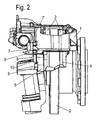
- FIG. 2 shows the disc brake of FIG. 1 in a side view
- FIG. 3 shows a detail of the disc brake according to FIGS. 1 and 2 in a perspective representation
- FIG. 4 shows another illustrative embodiment of a disc brake according to the invention, likewise in a perspective view
- FIG. 5 shows a detail of the disc brake according to FIG. 4 in a diagrammatic view.
- FIGS. 1 , 2 and 4 each show a disc brake for a commercial vehicle, with a brake caliper 1 , which is held slidably by means of guiding elements 7 on a brake carrier 4 , which is fixed with screws 6 to an axle connection 5 on the vehicle side.
- the brake caliper 1 straddles a brake disc 2 , against which brake pads 3 can be pressed from both sides during a braking operation.
- a brake application device 15 is provided, which can be operated pneumatically or by electric motor.
- At least the brake pad 3 on the application side is mounted in a pad well of the brake carrier 4 in such a way that it can be made to slide in the direction of the brake disc 2 .
- the screws or bolts 6 by which the brake carrier 4 is fixed to the axle connection 5 rest with their head ends against that side of the axle connection 5 which faces away from the brake carrier 4 , while being screwed into threaded holes in the brake carrier 4 .
- a pointer element 8 is connected to at least one of the screws 6 and, in the illustrative embodiment according to FIGS. 1 to 3 , has two press-fit sleeves 10 , which are connected to one another by an integrally formed plate 11 ( FIG. 3 ) and are pressed onto two heads of mutually adjacent screws (bolts) 6 .
- the plate 11 has formed on it a pointer pin 9 , which extends away from the brake disc 2 .
- the pointer pin 9 which extends parallel to the guide sleeve 7 ′, forms a wear detector. Since the brake caliper 1 moves in the direction of extension of the pointer pin 9 as the wear of the brake pads 3 and of the brake disc 2 increases, the distance X between the free end edge of the pointer pin 9 and the end of the guide sleeve 7 ′ decreases, and this is then a recognizable measure of the wear which has occurred.
- the pointer element 8 i.e. the plate 11 , the press-fit sleeves 10 and the pointer pin 9 can be formed in one piece from metal or from a suitable plastic.
- the pointer element 8 is a pointer sleeve 12 , which is pushed onto one of the screw heads 6 and is held on the head of the screw 6 in a manner secured against sliding and twisting by way of a clamping screw 14 , which is screwed into a lateral threaded hole 13 .
Landscapes
- Engineering & Computer Science (AREA)
- General Engineering & Computer Science (AREA)
- Mechanical Engineering (AREA)
- Braking Arrangements (AREA)
Applications Claiming Priority (4)
| Application Number | Priority Date | Filing Date | Title |
|---|---|---|---|
| DE102008034653.5 | 2008-07-25 | ||
| DE102008034653A DE102008034653A1 (de) | 2008-07-25 | 2008-07-25 | Scheibenbremse, insbesondere für ein Nutzfahrzeug |
| DE102008034653 | 2008-07-25 | ||
| PCT/EP2009/005356 WO2010009885A1 (fr) | 2008-07-25 | 2009-07-23 | Frein à disque, en particulier pour véhicule utilitaire |
Related Parent Applications (1)
| Application Number | Title | Priority Date | Filing Date |
|---|---|---|---|
| PCT/EP2009/005356 Continuation WO2010009885A1 (fr) | 2008-07-25 | 2009-07-23 | Frein à disque, en particulier pour véhicule utilitaire |
Publications (2)
| Publication Number | Publication Date |
|---|---|
| US20110186391A1 US20110186391A1 (en) | 2011-08-04 |
| US8752678B2 true US8752678B2 (en) | 2014-06-17 |
Family
ID=41059717
Family Applications (1)
| Application Number | Title | Priority Date | Filing Date |
|---|---|---|---|
| US13/012,237 Active 2030-02-07 US8752678B2 (en) | 2008-07-25 | 2011-01-24 | Disc brake, particularly for a commercial vehicle |
Country Status (9)
| Country | Link |
|---|---|
| US (1) | US8752678B2 (fr) |
| EP (1) | EP2304266B1 (fr) |
| CN (1) | CN102105720B (fr) |
| AT (1) | ATE543023T1 (fr) |
| BR (1) | BRPI0916814A2 (fr) |
| CA (1) | CA2731249C (fr) |
| DE (1) | DE102008034653A1 (fr) |
| RU (1) | RU2505721C2 (fr) |
| WO (1) | WO2010009885A1 (fr) |
Cited By (3)
| Publication number | Priority date | Publication date | Assignee | Title |
|---|---|---|---|---|
| US20170023082A1 (en) * | 2015-07-21 | 2017-01-26 | Meritor Heavy Vehicle Braking Systems (Uk) Limited | Disc Brake Assembly |
| US10041555B2 (en) | 2014-01-20 | 2018-08-07 | Knorr-Bremse Systeme Fuer Nutzfahrzeuge Gmbh | Disc brake for a commercial vehicle |
| US10436270B2 (en) * | 2015-03-31 | 2019-10-08 | Knorr-Bremse Systeme Fuer Nutzfahrzeuge Gmbh | Disc brake for a commercial vehicle |
Families Citing this family (9)
| Publication number | Priority date | Publication date | Assignee | Title |
|---|---|---|---|---|
| DE102010033563A1 (de) * | 2010-07-27 | 2012-02-02 | Stromag Wep Gmbh | Scheibenbremse für einen Azimutantrieb einer Windkraftanlage |
| WO2012149603A1 (fr) * | 2011-05-02 | 2012-11-08 | Martin James Pty Ltd | Indicateur d'usure de plaquette de frein |
| DE102011114107C5 (de) * | 2011-09-22 | 2017-07-27 | Knorr-Bremse Systeme für Nutzfahrzeuge GmbH | Bremssattel einer Scheibenbremse für ein Nutzfahrzeug |
| DE102012013526B4 (de) * | 2012-07-06 | 2020-09-24 | Knorr-Bremse Systeme für Nutzfahrzeuge GmbH | Bremsbelag einer Scheibenbremse und Scheibenbremse |
| DE102013016312A1 (de) * | 2013-10-04 | 2015-04-09 | Knorr-Bremse Systeme für Nutzfahrzeuge GmbH | Scheibenbremse |
| DE102014111405A1 (de) * | 2014-08-11 | 2016-02-11 | Knorr-Bremse Systeme für Nutzfahrzeuge GmbH | Achsflansch und Bremsträger |
| DE102014115765A1 (de) * | 2014-10-30 | 2016-05-04 | Knorr-Bremse Systeme für Nutzfahrzeuge GmbH | Scheibenbremse für ein Nutzfahrzeug |
| DE102014017438A1 (de) * | 2014-11-25 | 2016-05-25 | Wabco Europe Bvba | Scheibenbremse. insbesondere für Nutzfahrzeuge |
| DE102016104969A1 (de) * | 2015-10-09 | 2017-04-13 | Knorr-Bremse Systeme für Nutzfahrzeuge GmbH | Scheibenbremse für ein Nutzfahrzeug |
Citations (16)
| Publication number | Priority date | Publication date | Assignee | Title |
|---|---|---|---|---|
| US2905277A (en) * | 1955-06-15 | 1959-09-22 | Airheart Prod | Vehicle braking operator with slack adjustor |
| US3961690A (en) | 1974-02-20 | 1976-06-08 | Itt Industries, Inc. | Disc brake |
| US4356897A (en) * | 1978-12-29 | 1982-11-02 | Eaton Corporation | Wear indicator for disc brakes |
| US4391355A (en) * | 1979-12-03 | 1983-07-05 | Kelsey-Hayes Company | Sliding caliper disc brake |
| US4658936A (en) * | 1985-07-25 | 1987-04-21 | Goodyear Aerospace Corporation | Brake temperature and wear indicator |
| US4850454A (en) | 1988-07-29 | 1989-07-25 | Allied-Signal Inc. | Disc brake lining wear sensor |
| DE3914399A1 (de) * | 1989-02-04 | 1990-10-31 | Teves Gmbh Alfred | Reibbelag-warneinrichtung |
| US5228541A (en) * | 1991-12-18 | 1993-07-20 | The Boeing Company | Aircraft brake wear limit indicator having integral configuration control and method |
| DE3612166C2 (de) | 1986-04-11 | 1995-05-11 | Teves Gmbh Alfred | Belagverschleißanzeige für Teilbelag-Scheibenbremsen, insbesondere für Kraftfahrzeuge |
| US6076639A (en) * | 1996-06-13 | 2000-06-20 | Volvo Wheel Loaders Ab | Mechanically adjustable wear indicator |
| US6213254B1 (en) | 1999-02-08 | 2001-04-10 | Vernon L. Lanou, Jr. | Air-brake rod travel indicator |
| DE10201901A1 (de) | 2002-01-19 | 2003-08-14 | Knorr Bremse Systeme | Scheibenbremse, insbesondere für ein Nutzfahrzeug, mit Belagverschleißanzeige |
| US20050121265A1 (en) * | 2003-12-04 | 2005-06-09 | Wabco Radbremsen Gmbh | Disc brake and monitoring device for such a disc brake |
| US20050252727A1 (en) * | 2004-05-13 | 2005-11-17 | England Tom P | Brake pad wear indicator |
| US20070012525A1 (en) | 2005-07-18 | 2007-01-18 | Bendix Commercial Vehicle System Llc | Disc brake friction couple wear indicator |
| US7284642B2 (en) | 2004-01-21 | 2007-10-23 | Knorr-Bremse Systeme Fuer Nutzfahrzeuge Gmbh | Disc brake, in particular for a commercial vehicle |
Family Cites Families (3)
| Publication number | Priority date | Publication date | Assignee | Title |
|---|---|---|---|---|
| SU1323789A1 (ru) * | 1986-03-12 | 1987-07-15 | Московский автомеханический институт | Дисковый тормоз |
| FR2716509B1 (fr) * | 1994-01-19 | 1996-04-12 | Alliedsignal Automotive Espana | Frein à disque à sécurité accrue. |
| DE10311896A1 (de) * | 2003-03-18 | 2004-09-30 | Knorr-Bremse Systeme für Nutzfahrzeuge GmbH | Scheibenbremse, insbesondere für Nutzfahrzeuge |
-
2008
- 2008-07-25 DE DE102008034653A patent/DE102008034653A1/de not_active Withdrawn
-
2009
- 2009-07-23 CA CA2731249A patent/CA2731249C/fr not_active Expired - Fee Related
- 2009-07-23 CN CN200980128862.XA patent/CN102105720B/zh not_active Expired - Fee Related
- 2009-07-23 RU RU2011107211/11A patent/RU2505721C2/ru active
- 2009-07-23 BR BRPI0916814A patent/BRPI0916814A2/pt not_active IP Right Cessation
- 2009-07-23 WO PCT/EP2009/005356 patent/WO2010009885A1/fr not_active Ceased
- 2009-07-23 EP EP09777397A patent/EP2304266B1/fr active Active
- 2009-07-23 AT AT09777397T patent/ATE543023T1/de active
-
2011
- 2011-01-24 US US13/012,237 patent/US8752678B2/en active Active
Patent Citations (16)
| Publication number | Priority date | Publication date | Assignee | Title |
|---|---|---|---|---|
| US2905277A (en) * | 1955-06-15 | 1959-09-22 | Airheart Prod | Vehicle braking operator with slack adjustor |
| US3961690A (en) | 1974-02-20 | 1976-06-08 | Itt Industries, Inc. | Disc brake |
| US4356897A (en) * | 1978-12-29 | 1982-11-02 | Eaton Corporation | Wear indicator for disc brakes |
| US4391355A (en) * | 1979-12-03 | 1983-07-05 | Kelsey-Hayes Company | Sliding caliper disc brake |
| US4658936A (en) * | 1985-07-25 | 1987-04-21 | Goodyear Aerospace Corporation | Brake temperature and wear indicator |
| DE3612166C2 (de) | 1986-04-11 | 1995-05-11 | Teves Gmbh Alfred | Belagverschleißanzeige für Teilbelag-Scheibenbremsen, insbesondere für Kraftfahrzeuge |
| US4850454A (en) | 1988-07-29 | 1989-07-25 | Allied-Signal Inc. | Disc brake lining wear sensor |
| DE3914399A1 (de) * | 1989-02-04 | 1990-10-31 | Teves Gmbh Alfred | Reibbelag-warneinrichtung |
| US5228541A (en) * | 1991-12-18 | 1993-07-20 | The Boeing Company | Aircraft brake wear limit indicator having integral configuration control and method |
| US6076639A (en) * | 1996-06-13 | 2000-06-20 | Volvo Wheel Loaders Ab | Mechanically adjustable wear indicator |
| US6213254B1 (en) | 1999-02-08 | 2001-04-10 | Vernon L. Lanou, Jr. | Air-brake rod travel indicator |
| DE10201901A1 (de) | 2002-01-19 | 2003-08-14 | Knorr Bremse Systeme | Scheibenbremse, insbesondere für ein Nutzfahrzeug, mit Belagverschleißanzeige |
| US20050121265A1 (en) * | 2003-12-04 | 2005-06-09 | Wabco Radbremsen Gmbh | Disc brake and monitoring device for such a disc brake |
| US7284642B2 (en) | 2004-01-21 | 2007-10-23 | Knorr-Bremse Systeme Fuer Nutzfahrzeuge Gmbh | Disc brake, in particular for a commercial vehicle |
| US20050252727A1 (en) * | 2004-05-13 | 2005-11-17 | England Tom P | Brake pad wear indicator |
| US20070012525A1 (en) | 2005-07-18 | 2007-01-18 | Bendix Commercial Vehicle System Llc | Disc brake friction couple wear indicator |
Non-Patent Citations (2)
| Title |
|---|
| German Office Action dated Mar. 27, 2009 including English-language translation (Six (6) pages). |
| International Search Report dated Sep. 25, 2009 including English-language translation (Six (6) pages). |
Cited By (4)
| Publication number | Priority date | Publication date | Assignee | Title |
|---|---|---|---|---|
| US10041555B2 (en) | 2014-01-20 | 2018-08-07 | Knorr-Bremse Systeme Fuer Nutzfahrzeuge Gmbh | Disc brake for a commercial vehicle |
| US10436270B2 (en) * | 2015-03-31 | 2019-10-08 | Knorr-Bremse Systeme Fuer Nutzfahrzeuge Gmbh | Disc brake for a commercial vehicle |
| US20170023082A1 (en) * | 2015-07-21 | 2017-01-26 | Meritor Heavy Vehicle Braking Systems (Uk) Limited | Disc Brake Assembly |
| US9915310B2 (en) * | 2015-07-21 | 2018-03-13 | Meritor Heavy Vehicle Braking Systems (Uk) Limited | Disc brake assembly |
Also Published As
| Publication number | Publication date |
|---|---|
| WO2010009885A8 (fr) | 2011-02-03 |
| CN102105720B (zh) | 2015-06-17 |
| RU2505721C2 (ru) | 2014-01-27 |
| ATE543023T1 (de) | 2012-02-15 |
| WO2010009885A1 (fr) | 2010-01-28 |
| BRPI0916814A2 (pt) | 2019-09-24 |
| DE102008034653A1 (de) | 2010-01-28 |
| CN102105720A (zh) | 2011-06-22 |
| CA2731249C (fr) | 2017-02-28 |
| EP2304266B1 (fr) | 2012-01-25 |
| CA2731249A1 (fr) | 2010-01-28 |
| US20110186391A1 (en) | 2011-08-04 |
| EP2304266A1 (fr) | 2011-04-06 |
| RU2011107211A (ru) | 2012-08-27 |
Similar Documents
| Publication | Publication Date | Title |
|---|---|---|
| US8752678B2 (en) | Disc brake, particularly for a commercial vehicle | |
| CN103313890B (zh) | 制动器监测装置及与其关联的部件 | |
| US10233984B2 (en) | Multiple function brake caliper guide pin | |
| US9915310B2 (en) | Disc brake assembly | |
| US9394954B2 (en) | Guide pin for disc brake assembly and disc brake assembly including such a guide pin | |
| EP2584212B1 (fr) | Frein à disque d'arrêt mécanique | |
| US9958021B2 (en) | Brake pad retainer for a disc brake | |
| US20050173205A1 (en) | Disc brake equipped with a floating caliper and several outer brake pads directly supported on the brake anchor plate | |
| WO1998037338A1 (fr) | Indicateur visuel de course de freinage | |
| EP4105510B1 (fr) | Frein à disque à air pour véhicule routier | |
| US20070170019A1 (en) | Symmetric brake clip | |
| DE102005013142A1 (de) | Bremskraftmessvorrichtung für eine Reibungsbremse | |
| US10436270B2 (en) | Disc brake for a commercial vehicle | |
| CN1502018A (zh) | 将电连接件固定到盘式制动器测径仪上的系统 | |
| KR101783168B1 (ko) | 브레이크패드 마모도 관리 시스템 | |
| US20160327111A1 (en) | Disc Brake for a Commercial Vehicle | |
| CN210290550U (zh) | 制动卡钳、制动装置和车辆 | |
| US4311214A (en) | Disc brake | |
| DE10019654C2 (de) | Scheibenbremse | |
| CN112178084B (zh) | 用于轨道车辆制动衬片支架的衬片保持器 | |
| WO2025196162A1 (fr) | Procédé de détermination de l'usure de plaquettes de frein d'un frein à disque, et frein à disque comportant un dispositif de mesure pour la mise en œuvre du procédé | |
| KR101282672B1 (ko) | 드럼 브레이크용 마찰재 경도의 측정지그 | |
| CA2228086A1 (fr) | Indicateur visuel planaire de poussee de freinage | |
| SE530560C2 (sv) | Fästanordning jämte fordon | |
| BR112018015509B1 (pt) | Conjunto de guarnições de fricção e freio de disco de pinça deslizante |
Legal Events
| Date | Code | Title | Description |
|---|---|---|---|
| AS | Assignment |
Owner name: KNORR-BREMSE SYSTEME FUER NUTZFAHRZEUGE GMBH, GERM Free format text: ASSIGNMENT OF ASSIGNORS INTEREST;ASSIGNORS:GRUBER, MARKUS;RENO, THOMAS;SIGNING DATES FROM 20110204 TO 20110404;REEL/FRAME:026144/0369 |
|
| STCF | Information on status: patent grant |
Free format text: PATENTED CASE |
|
| MAFP | Maintenance fee payment |
Free format text: PAYMENT OF MAINTENANCE FEE, 4TH YEAR, LARGE ENTITY (ORIGINAL EVENT CODE: M1551) Year of fee payment: 4 |
|
| MAFP | Maintenance fee payment |
Free format text: PAYMENT OF MAINTENANCE FEE, 8TH YEAR, LARGE ENTITY (ORIGINAL EVENT CODE: M1552); ENTITY STATUS OF PATENT OWNER: LARGE ENTITY Year of fee payment: 8 |
|
| FEPP | Fee payment procedure |
Free format text: MAINTENANCE FEE REMINDER MAILED (ORIGINAL EVENT CODE: REM.); ENTITY STATUS OF PATENT OWNER: LARGE ENTITY |