US879227A - Pneumatic motor. - Google Patents
Pneumatic motor. Download PDFInfo
- Publication number
- US879227A US879227A US33147806A US1906331478A US879227A US 879227 A US879227 A US 879227A US 33147806 A US33147806 A US 33147806A US 1906331478 A US1906331478 A US 1906331478A US 879227 A US879227 A US 879227A
- Authority
- US
- United States
- Prior art keywords
- air
- chamber
- casing
- collecting chamber
- wheel
- Prior art date
- Legal status (The legal status is an assumption and is not a legal conclusion. Google has not performed a legal analysis and makes no representation as to the accuracy of the status listed.)
- Expired - Lifetime
Links
- 241000892865 Heros Species 0.000 description 1
- 238000010276 construction Methods 0.000 description 1
- 238000012856 packing Methods 0.000 description 1
- 230000000630 rising effect Effects 0.000 description 1
Images


Classifications
-
- F—MECHANICAL ENGINEERING; LIGHTING; HEATING; WEAPONS; BLASTING
- F02—COMBUSTION ENGINES; HOT-GAS OR COMBUSTION-PRODUCT ENGINE PLANTS
- F02K—JET-PROPULSION PLANTS
- F02K9/00—Rocket-engine plants, i.e. plants carrying both fuel and oxidant therefor; Control thereof
- F02K9/42—Rocket-engine plants, i.e. plants carrying both fuel and oxidant therefor; Control thereof using liquid or gaseous propellants
- F02K9/60—Constructional parts; Details not otherwise provided for
- F02K9/68—Decomposition chambers
Definitions
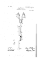
- Vehicles of the bicycle or tricycle tvpe have heretofore been propelled by hand, foot or motor power, and 1t is intended to supply by the present invention a modified form of motor driven vehicles, in which the driving power is represented by compressed air, while its mode of utilization is based upon the aeolopile or Heros engine.
- Compressed air is produced by footpower, using a pair of air compressors of simple and efficient construction, which are located on azbicycle in the lace of the usual pedals. .A number of condhits lead from the air compressors to'a common valve, operated in such a way, that with the operation of the air compressors, the sliding member of the valve is displaced, causing alternate connection between the operating compressors and the
- the latter is preferably located at-the hub portion of the rear ior'fdriving'whoel and connected again with .one or more operatin cylinders, located at the 'eriphery of the riv-ing Wheel.
- T ecompressed air when stored in the collectingchamber; and passing intothe 1" ance' that it will cause the rotation of the.
- Figure 1 isa-sideiview of a part of a bicycle, showing the complete device
- Fig. 1 is a diagrammatical plan view of the same
- Fig. 2 is a ver- "'tical cross section through one of the air.
- FIG. 3 is a horiz'ontal'cross section infthe line 3 3 of Fig. 2
- Fig. 4 is a side yiew of the upper end of an air compressor
- Figs. 5 and 6 are horizontal cross sections of the valve
- Fig. 7 is a vertical cross section in line 7-7 of Fig. 5.
- Fig. 8 is a vertical cross section the axis ofithe collecting chamber
- the air com ressors are preferabl located at the usua junction of the bicyc eframe, and the conduits as well as the valve chamber and check valve are laced along and supported by the horizonta' strut of the frame.
- the collecting chamber 6 is arranged on the shaft of the driving wheel of the bicycle, the conduits 7, leading therefrom -in a radial direction, may be connected to the spokes of the wheel, and the operating chambers 8 and 9 are located at or near the rim of the driving Wheel.
- the open ends of the operating chambers are placed in opposite tangential direction in relation to the rim of the wheel, so that one operating chamber or set of chambers will cause the wheel to ro tate one way, whereas the other chamber or set of chambers will cause it to rotate in the other or opposite direction.
- FIGs. 2, 3 and 4 illustrate the air compressors, of which there are two in number, one on each side of the frame of the bicycle and adapted to be operated by the left and right foot of therider one foot rising when the other descends.
- Each compressor consists of a cylindrical casing 10, open at the upper end and containing a piston 11, having a series of valves 12, as Well known. in the art and used in-air compressors of this general character.
- the piston is provided with a number of guide rods 14, carrying a platform 15, having a toe-holder or toe-clip 16. The foot of the rider rests on this plate and by its up and down movement compresses the air in the cylinder.
- the guides 14 slide in guide Ways 17 on the inner wall of the cylinder.
- Thegu'ide rods 14 are notnecessarily located within the cylinder, but may be outside of the same, or other suitable means may be provided to more securely support the platform 15.
- valve chamber 3 which consists of a rectangular box having its front end curved, and containing 'a sliding .member'18, oscillatin on a pivot 19 and preferably provided wit h packingh20 and 21..
- the upper t e sliding member ought tact with the corresponding faces of. the valve chamber.” 'It is seen that when air is forced into the valve chamber from.
- the collecting chamber 6,- (Figs. 8 and 9) com rises a cylmdrical casing 22, secured. to the s aft 23 of the driving wheel.
- twohub-portions of this casing is left off, and its place is taken by a stationary annular disk 24 secured to :the frame of the wheel and containing an opening for the conduit 4.
- An inner sleeve 27 is well fitted in the casing 22, and rovided with ports, 28 and 29, one of W ich only coincides at one time with one of the conduits 7 leading to the operating chambers.
- an outer sleeve 30 is provided, having a series of pins 31, passing throu h corresponding, elongated openings 32 in tie casing 22, and connecting the outer sleeve with the inner sleeve.
- the operating chambers (Figs. 10 and 11) comprise a casing 33 of any suitablecross section, closed at one end, and covered at the open end with a lid-34, controlled by a helical s ring 35 supported by-a hood 36, secured to t e casing 33, this s' ring is adjustable by a screw 37.
- the hoo or more apertures 38 comprise a casing 33 of any suitablecross section, closed at one end, and covered at the open end with a lid-34, controlled by a helical s ring 35 supported by-a hood 36, secured to t e casing 33, this s' ring is adjustable by a screw 37.
- the hoo or more apertures 38 The hoo or more apertures 38.
- the compressed air in the collecting chamber will pass through one of the ports and the corresponding conduit to one of'the operating chambers, lift the lid of the same and esca e through the apertures in the hood into t e open air, causing rotation of the wheel by reaction.
- a device 43 for the purpose of reversing the direction in which t e Wheel is driven or for braking the wheel, a device 43 is provided, comprising a rod 39 (Fig. 9), and a roller 40.
- a roller 40 When the roller 40 is forced in horizontal direction against the sleeve 30, which rotates normally with the casing 22, secured to the shaft 23,
- One of the 36 is provided with one.
- roller will cause retardation of the rotation of the sleeve and a shifting of the same, so that the port coinciding at that-moment with one of the conduits, 7, will be removed from the latter, while the other port will be made to coincide with the other conduit. leading to the opposite operating chamber which, as already stated, sends its compressed air' in a tangential direction opposite to the direction in which the compressed air of the first operating chamber escapes.
- a spring 41 is provided on oneof the conduits, so that when the pressure of the roller 40-on the sleeve 30 is'terminated, the pressure of the spring 41 on the shoulder 42, secured to said s eeve', will cause the same to return to its first position.
Landscapes
- Engineering & Computer Science (AREA)
- Chemical & Material Sciences (AREA)
- Combustion & Propulsion (AREA)
- Mechanical Engineering (AREA)
- General Engineering & Computer Science (AREA)
- Vehicle Body Suspensions (AREA)
Description
No. 879,227. PATENTED FEB. 18, 1908.
G. G. WIELAND.
PNEUMATIC MOTOR.
unwuxon FILED we. 21, 1906.
4 SHEETS-SHEET 1.
WITNESSES PATENTED FEB. 18, 1908.
0. er. WIELANDQ PNEUMATIC MOTOR.
APPLIOAT IOH FILED AUG. 21, 1908.
4 snhms-sxnnr a.
Z INVENTOR WWI/44*;
m -d ,4; ATTORNEY; Z
PATENTED FEB. 18, 1908.
0. G'. WIELAND. PNEUMATIC MOTOR. APPLICATION FILED AUG. 21, 1906.
4 SHEETS-SHEET 3.
///////A/////////////////////////l V E L n W I i l M l l 9 l 1 w R J W 1a.. ZI/H/V V/ll/l/ mvmron wlmasssi PATENTED FEB. 18, 1908.
G. G. WIELAND.
PNEUMATIC MOTOR.
APPLIOATION-FILED AUG.21,1906.
4 SHEETS-SHEET 4.
INVENTOH BY W 1 I J), A7T0'RNEY iqg/TNESFES collecting chamber.
CHARLES G. WIELAND OF HOBOKEN, NEW JERSEY.
PNEUMATIC MOTOR.
Specification of Letters Patent.
Patented Feb. 18, 1908.
Application filed August 21. 1906. Serial No. 331.478.
To all whom it may concern:
Be it known that 1, CHARLES G. WIELAND, a citizen of the German Empire, and'resident of Hoboken, in the county of I-Iudson and State of New Jersey, have invented certain new and useful Improvements in Pneumatic Motors, of which the following is a specification.
Vehicles of the bicycle or tricycle tvpe have heretofore been propelled by hand, foot or motor power, and 1t is intended to supply by the present invention a modified form of motor driven vehicles, in which the driving power is represented by compressed air, while its mode of utilization is based upon the aeolopile or Heros engine.
Compressed air is produced by footpower, using a pair of air compressors of simple and efficient construction, which are located on azbicycle in the lace of the usual pedals. .A number of condhits lead from the air compressors to'a common valve, operated in such a way, that with the operation of the air compressors, the sliding member of the valve is displaced, causing alternate connection between the operating compressors and the The latter is preferably located at-the hub portion of the rear ior'fdriving'whoel and connected again with .one or more operatin cylinders, located at the 'eriphery of the riv-ing Wheel.
T ecompressed air, when stored in the collectingchamber; and passing intothe 1" ance' that it will cause the rotation of the.
'o crating chambers, will, in time, overcome eresist'ance of the spring controlled cover and escape through the hood and its outlets into the open air, where it finds such resistdriving wheel to which the operating cylinders-are connected.v n,
' In the accompanying drawings, Figure 1 isa-sideiview of a part of a bicycle, showing the complete device, Fig. 1 is a diagrammatical plan view of the same, Fig. 2 is a ver- "'tical cross section through one of the air.
" compressors, Fig; 3 isa horiz'ontal'cross section infthe line 3 3 of Fig. 2, Fig. 4 is a side yiew of the upper end of an air compressor, Figs. 5 and 6 are horizontal cross sections of the valve, Fig. 7 is a vertical cross section in line 7-7 of Fig. 5. ,Fig. 8 is a vertical cross section the axis ofithe collecting chamber,
5 and the collecting chamber 6. As shown in the drawings, the air com ressors are preferabl located at the usua junction of the bicyc eframe, and the conduits as well as the valve chamber and check valve are laced along and supported by the horizonta' strut of the frame. The collecting chamber 6 is arranged on the shaft of the driving wheel of the bicycle, the conduits 7, leading therefrom -in a radial direction, may be connected to the spokes of the wheel, and the operating chambers 8 and 9 are located at or near the rim of the driving Wheel. The open ends of the operating chambers are placed in opposite tangential direction in relation to the rim of the wheel, so that one operating chamber or set of chambers will cause the wheel to ro tate one way, whereas the other chamber or set of chambers will cause it to rotate in the other or opposite direction.
Figs. 2, 3 and 4 illustrate the air compressors, of which there are two in number, one on each side of the frame of the bicycle and adapted to be operated by the left and right foot of therider one foot rising when the other descends. Each compressor consists of a cylindrical casing 10, open at the upper end and containing a piston 11, having a series of valves 12, as Well known. in the art and used in-air compressors of this general character. The piston is provided with a number of guide rods 14, carrying a platform 15, having a toe-holder or toe-clip 16. The foot of the rider rests on this plate and by its up and down movement compresses the air in the cylinder. The guides 14 slide in guide Ways 17 on the inner wall of the cylinder.
Thegu'ide rods 14 are notnecessarily located within the cylinder, but may be outside of the same, or other suitable means may be provided to more securely support the platform 15.
The compressed air is led through the conand lower face of d to be well ground, so as to form perfect conduit 2 to the valve chamber 3, which consists of a rectangular box having its front end curved, and containing 'a sliding .member'18, oscillatin on a pivot 19 and preferably provided wit h packingh20 and 21.. The upper t e sliding member ought tact with the corresponding faces of. the valve chamber." 'It is seen that when air is forced into the valve chamber from. one
side it will cause the sliding member 18 to oscillate to the opposite side and open a path for the com ressed air from the operating compressor t rough the conduit 4-and check valve 5, located therein, to the collecting chamber 6. The air, of course, cannot return on account of the check valve. 4
The collecting chamber 6,- (Figs. 8 and 9) com rises a cylmdrical casing 22, secured. to the s aft 23 of the driving wheel. twohub-portions of this casing is left off, and its place is taken by a stationary annular disk 24 secured to :the frame of the wheel and containing an opening for the conduit 4. It is obviously provided with suitable packings 25 and 26, so as to make the collecting chamber entirely airtight. An inner sleeve 27 is well fitted in the casing 22, and rovided with ports, 28 and 29, one of W ich only coincides at one time with one of the conduits 7 leading to the operating chambers. For the purpose'of turnmg this sleeve an outer sleeve 30 is provided, having a series of pins 31, passing throu h corresponding, elongated openings 32 in tie casing 22, and connecting the outer sleeve with the inner sleeve.
The operating chambers (Figs. 10 and 11) comprise a casing 33 of any suitablecross section, closed at one end, and covered at the open end with a lid-34, controlled by a helical s ring 35 supported by-a hood 36, secured to t e casing 33, this s' ring is adjustable by a screw 37. The hoo or more apertures 38.
As soon as the air pressure exceeds the outside pressure of the atmosphere, the compressed air in the collecting chamber will pass through one of the ports and the corresponding conduit to one of'the operating chambers, lift the lid of the same and esca e through the apertures in the hood into t e open air, causing rotation of the wheel by reaction. p
For the purpose of reversing the direction in which t e Wheel is driven or for braking the wheel, a device 43 is provided, comprising a rod 39 (Fig. 9), and a roller 40. When the roller 40 is forced in horizontal direction against the sleeve 30, which rotates normally with the casing 22, secured to the shaft 23,
One of the 36 is provided with one.
erase? the roller will cause retardation of the rotation of the sleeve and a shifting of the same, so that the port coinciding at that-moment with one of the conduits, 7, will be removed from the latter, while the other port will be made to coincide with the other conduit. leading to the opposite operating chamber which, as already stated, sends its compressed air' in a tangential direction opposite to the direction in which the compressed air of the first operating chamber escapes. For the pur ose of returning the sleeve 30 to its norma position, a spring 41 is provided on oneof the conduits, so that when the pressure of the roller 40-on the sleeve 30 is'terminated, the pressure of the spring 41 on the shoulder 42, secured to said s eeve', will cause the same to return to its first position.
As new and useful is claimed and desired to be secured by Letters Patent of the United States 1. The combination with a vehicle, of a plurality of air com ressors. a common valve chamber, a-conduiteading from each of said compressors to 'said valve chamber, a collecting chamber, a conduit leading from said valve chamber to said collecting chamber, a plurality of operating chambers, each of them comprising a casing open at one end, a spring controlled cover for the open end of said casing and a hood surrounding said cover and having one or more outlets, and a conduit leading from said collecting chamber to each of said operating chambers.
2. The combination with a vehicle, plurality of air compressors, a common valve chamber, a conduit leading from each of'said compressors to said valve chamber, a collecting chamber, a conduit leading from said valve chamber to said collecting chamber, a plurality of operating chambers located near ofa to the rim of the vehicle-wheel, each of them comprising a casing open at one end and a spring controlled cover for the open end of said casing and a hood surrounding said cover and having one or more outlets, and a conduit leading from said collecting chamber to each of-said operating chambers.
3. The combination with a vehicle,- of a plurality of air compressors, a common valve chamber, a conduit leading from each of said compressors to said valve chamber, a collecting chamber, a conduit leading from said valve chamber to' said collecting chamber, a check-valve in said conduit, a plurality of operatin chambers located near to the rim of the ve icle wheel, each of them comprising a casing open at one end and a spring controlled cover for theopen end of said casing and a hood surrounding said cover and having one or more outlets, and a conduit leading from said collecting chamber to each of Signed at New York, in the county of New said operating chambers. York and State of New York, this 13th day 10 4. An operating chamber, collnprising a of August, A. D. 1906.
casin open at one end a conduit eadin into a r Y said gasing, a spring-cbntrolled cover f r the CHARLEb W IELAA open end of the casing, a hood surrounding Witnesses:
said cover, and one or more outlets in said RALPH J. SAOHERS,
hood. M. F. Woon.
Priority Applications (1)
| Application Number | Priority Date | Filing Date | Title |
|---|---|---|---|
| US33147806A US879227A (en) | 1906-08-21 | 1906-08-21 | Pneumatic motor. |
Applications Claiming Priority (1)
| Application Number | Priority Date | Filing Date | Title |
|---|---|---|---|
| US33147806A US879227A (en) | 1906-08-21 | 1906-08-21 | Pneumatic motor. |
Publications (1)
| Publication Number | Publication Date |
|---|---|
| US879227A true US879227A (en) | 1908-02-18 |
Family
ID=2947667
Family Applications (1)
| Application Number | Title | Priority Date | Filing Date |
|---|---|---|---|
| US33147806A Expired - Lifetime US879227A (en) | 1906-08-21 | 1906-08-21 | Pneumatic motor. |
Country Status (1)
| Country | Link |
|---|---|
| US (1) | US879227A (en) |
-
1906
- 1906-08-21 US US33147806A patent/US879227A/en not_active Expired - Lifetime
Similar Documents
| Publication | Publication Date | Title |
|---|---|---|
| US1657412A (en) | Steering arrangement for heavy motor vehicles | |
| US879227A (en) | Pneumatic motor. | |
| US888806A (en) | Rotary engine. | |
| US602618A (en) | eyster | |
| US1054504A (en) | Means for tire inflation. | |
| US6962A (en) | thompson | |
| US2290932A (en) | Brake and booster apparatus | |
| US540519A (en) | Philip w | |
| US1189042A (en) | Power transmission and control. | |
| US1278126A (en) | Reversible rotary motor. | |
| US987728A (en) | Self-propelled vehicle. | |
| US752997A (en) | Grip-wheel | |
| US597456A (en) | Pneumatic bicycle-brake | |
| US610956A (en) | Propelling mechanism for bicycles or similar vehicles | |
| US651157A (en) | Fluid-pressure motor. | |
| US573580A (en) | Wheel pump | |
| US907105A (en) | Steering device for motor-vehicles. | |
| US590511A (en) | Engine | |
| US853848A (en) | Brake. | |
| US944221A (en) | Water-motor. | |
| US626440A (en) | raders | |
| US1256501A (en) | Hydraulic variable-speed transmission. | |
| US640284A (en) | Hydraulic motor. | |
| US998172A (en) | Pump for inflating rubber tires. | |
| US714874A (en) | Pressure-creating device for cash-carrier systems. |