US8801381B2 - Turbine blade - Google Patents
Turbine blade Download PDFInfo
- Publication number
- US8801381B2 US8801381B2 US12/877,354 US87735410A US8801381B2 US 8801381 B2 US8801381 B2 US 8801381B2 US 87735410 A US87735410 A US 87735410A US 8801381 B2 US8801381 B2 US 8801381B2
- Authority
- US
- United States
- Prior art keywords
- airfoil
- platform
- blade
- seal
- hot gases
- Prior art date
- Legal status (The legal status is an assumption and is not a legal conclusion. Google has not performed a legal analysis and makes no representation as to the accuracy of the status listed.)
- Expired - Fee Related, expires
Links
Images



Classifications
-
- F—MECHANICAL ENGINEERING; LIGHTING; HEATING; WEAPONS; BLASTING
- F01—MACHINES OR ENGINES IN GENERAL; ENGINE PLANTS IN GENERAL; STEAM ENGINES
- F01D—NON-POSITIVE DISPLACEMENT MACHINES OR ENGINES, e.g. STEAM TURBINES
- F01D5/00—Blades; Blade-carrying members; Heating, heat-insulating, cooling or antivibration means on the blades or the members
- F01D5/12—Blades
- F01D5/14—Form or construction
- F01D5/147—Construction, i.e. structural features, e.g. of weight-saving hollow blades
-
- F—MECHANICAL ENGINEERING; LIGHTING; HEATING; WEAPONS; BLASTING
- F01—MACHINES OR ENGINES IN GENERAL; ENGINE PLANTS IN GENERAL; STEAM ENGINES
- F01D—NON-POSITIVE DISPLACEMENT MACHINES OR ENGINES, e.g. STEAM TURBINES
- F01D11/00—Preventing or minimising internal leakage of working-fluid, e.g. between stages
- F01D11/005—Sealing means between non relatively rotating elements
-
- F—MECHANICAL ENGINEERING; LIGHTING; HEATING; WEAPONS; BLASTING
- F01—MACHINES OR ENGINES IN GENERAL; ENGINE PLANTS IN GENERAL; STEAM ENGINES
- F01D—NON-POSITIVE DISPLACEMENT MACHINES OR ENGINES, e.g. STEAM TURBINES
- F01D9/00—Stators
- F01D9/02—Nozzles; Nozzle boxes; Stator blades; Guide conduits, e.g. individual nozzles
- F01D9/04—Nozzles; Nozzle boxes; Stator blades; Guide conduits, e.g. individual nozzles forming ring or sector
- F01D9/042—Nozzles; Nozzle boxes; Stator blades; Guide conduits, e.g. individual nozzles forming ring or sector fixing blades to stators
-
- F—MECHANICAL ENGINEERING; LIGHTING; HEATING; WEAPONS; BLASTING
- F05—INDEXING SCHEMES RELATING TO ENGINES OR PUMPS IN VARIOUS SUBCLASSES OF CLASSES F01-F04
- F05D—INDEXING SCHEME FOR ASPECTS RELATING TO NON-POSITIVE-DISPLACEMENT MACHINES OR ENGINES, GAS-TURBINES OR JET-PROPULSION PLANTS
- F05D2230/00—Manufacture
- F05D2230/20—Manufacture essentially without removing material
- F05D2230/23—Manufacture essentially without removing material by permanently joining parts together
- F05D2230/232—Manufacture essentially without removing material by permanently joining parts together by welding
- F05D2230/237—Brazing
-
- F—MECHANICAL ENGINEERING; LIGHTING; HEATING; WEAPONS; BLASTING
- F05—INDEXING SCHEMES RELATING TO ENGINES OR PUMPS IN VARIOUS SUBCLASSES OF CLASSES F01-F04
- F05D—INDEXING SCHEME FOR ASPECTS RELATING TO NON-POSITIVE-DISPLACEMENT MACHINES OR ENGINES, GAS-TURBINES OR JET-PROPULSION PLANTS
- F05D2240/00—Components
- F05D2240/55—Seals
-
- F—MECHANICAL ENGINEERING; LIGHTING; HEATING; WEAPONS; BLASTING
- F05—INDEXING SCHEMES RELATING TO ENGINES OR PUMPS IN VARIOUS SUBCLASSES OF CLASSES F01-F04
- F05D—INDEXING SCHEME FOR ASPECTS RELATING TO NON-POSITIVE-DISPLACEMENT MACHINES OR ENGINES, GAS-TURBINES OR JET-PROPULSION PLANTS
- F05D2240/00—Components
- F05D2240/55—Seals
- F05D2240/57—Leaf seals
-
- F—MECHANICAL ENGINEERING; LIGHTING; HEATING; WEAPONS; BLASTING
- F05—INDEXING SCHEMES RELATING TO ENGINES OR PUMPS IN VARIOUS SUBCLASSES OF CLASSES F01-F04
- F05D—INDEXING SCHEME FOR ASPECTS RELATING TO NON-POSITIVE-DISPLACEMENT MACHINES OR ENGINES, GAS-TURBINES OR JET-PROPULSION PLANTS
- F05D2240/00—Components
- F05D2240/80—Platforms for stationary or moving blades
-
- F—MECHANICAL ENGINEERING; LIGHTING; HEATING; WEAPONS; BLASTING
- F05—INDEXING SCHEMES RELATING TO ENGINES OR PUMPS IN VARIOUS SUBCLASSES OF CLASSES F01-F04
- F05D—INDEXING SCHEME FOR ASPECTS RELATING TO NON-POSITIVE-DISPLACEMENT MACHINES OR ENGINES, GAS-TURBINES OR JET-PROPULSION PLANTS
- F05D2260/00—Function
- F05D2260/94—Functionality given by mechanical stress related aspects such as low cycle fatigue [LCF] of high cycle fatigue [HCF]
-
- F—MECHANICAL ENGINEERING; LIGHTING; HEATING; WEAPONS; BLASTING
- F05—INDEXING SCHEMES RELATING TO ENGINES OR PUMPS IN VARIOUS SUBCLASSES OF CLASSES F01-F04
- F05D—INDEXING SCHEME FOR ASPECTS RELATING TO NON-POSITIVE-DISPLACEMENT MACHINES OR ENGINES, GAS-TURBINES OR JET-PROPULSION PLANTS
- F05D2260/00—Function
- F05D2260/94—Functionality given by mechanical stress related aspects such as low cycle fatigue [LCF] of high cycle fatigue [HCF]
- F05D2260/941—Functionality given by mechanical stress related aspects such as low cycle fatigue [LCF] of high cycle fatigue [HCF] particularly aimed at mechanical or thermal stress reduction
-
- F—MECHANICAL ENGINEERING; LIGHTING; HEATING; WEAPONS; BLASTING
- F05—INDEXING SCHEMES RELATING TO ENGINES OR PUMPS IN VARIOUS SUBCLASSES OF CLASSES F01-F04
- F05D—INDEXING SCHEME FOR ASPECTS RELATING TO NON-POSITIVE-DISPLACEMENT MACHINES OR ENGINES, GAS-TURBINES OR JET-PROPULSION PLANTS
- F05D2300/00—Materials; Properties thereof
- F05D2300/60—Properties or characteristics given to material by treatment or manufacturing
- F05D2300/601—Fabrics
-
- F—MECHANICAL ENGINEERING; LIGHTING; HEATING; WEAPONS; BLASTING
- F05—INDEXING SCHEMES RELATING TO ENGINES OR PUMPS IN VARIOUS SUBCLASSES OF CLASSES F01-F04
- F05D—INDEXING SCHEME FOR ASPECTS RELATING TO NON-POSITIVE-DISPLACEMENT MACHINES OR ENGINES, GAS-TURBINES OR JET-PROPULSION PLANTS
- F05D2300/00—Materials; Properties thereof
- F05D2300/60—Properties or characteristics given to material by treatment or manufacturing
- F05D2300/612—Foam
Definitions
- the present invention relates to a turbine blade.
- the present invention refers to a blade being a guide vane blade or rotor blade of a gas turbine.
- Blades are known to comprise an airfoil that projects in the hot gases path to guide the hot gases (guide vanes) or exchange mechanical power with the hot gases (rotor blades).
- blades also comprise platforms that close the space between adjacent airfoils and define a hot gases path.
- the blades are always thermally highly loaded.
- Thermal load causes differential deformations between the airfoil and platform that generate large forces that limit the blades service life.
- EP 0764765 discloses a blade having an airfoil and a platform made in two separate pieces.
- connection between the airfoil and the platform is realized at their zone facing the hot gases path, i.e. in the same zone where the forces due to the deformations caused by the hot gases temperature are larger.
- EP 1306523 discloses blades made of an airfoil and a platform in two separate pieces, but also in this case the connection between the airfoil and the platform is realized in their zone facing the hot gases path, because of the forces that during operation press the platform sides against the blade.
- U.S. Pat. No. 5,248,240 discloses a stator vane assembly made of airfoils connected to a platform.
- connection is realized in a zone of the airfoil and platform close to the hot gases path.
- U.S. Pat. No. 6,331,217 discloses blades made of a plurality of crystal super-alloy pieces joined together across all the surfaces between the pieces.
- connection between the pieces (and in particular between the pieces defining the airfoil and those defining the platform) is realized in zones close to the hot gases path.
- U.S. Pat. No. 7,284,958 discloses a blade made of an airfoil and a platform at the two opposite sides of the airfoil.
- the platforms are connected to the airfoil also in its zone close to the hot gases path.
- U.S. Pat. No. 2,656,146 discloses a further blade made of a platform having a through hole in which an airfoil is housed. Connection between platform and airfoil is established in the zone of the hole (i.e. close to the hot gases path).
- the disclosure is directed to a turbine blade including an airfoil and a platform manufactured in separate pieces joined together at a joint.
- a mechanically decoupled seal is interposed between the airfoil and the platform in a position closer to a hot gases path than the joint.
- FIG. 1 is a schematic view of a blade of a first embodiment of the invention
- FIG. 2 is another embodiment of the blade of the invention.
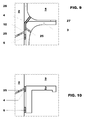
- FIGS. 3-10 are further embodiments the blade of the invention.
- FIG. 11 is a perspective view of an example of a blade according to the invention.
- the technical aim of the present invention is therefore to provide a blade (being a rotor blade or a guide vane) by which said problems of the known art are eliminated.
- an aspect of the invention is to provide a blade that has the airfoil and the platform connected together but at the same time in which the forces generated by the differential deformations of the airfoil and platform of each blade do not impair the service life of the same blade.
- a blade 1 of a turbine in particular the blade 1 can be a guide vane or a rotor blade of a gas turbine.
- the blade 1 comprises an airfoil 2 and a platform 3 manufactured in two separate pieces (airfoil and platform) or three separated pieces (airfoil and a platform for each side of the airfoil) that are joined together.
- the blade 1 comprises a seal 4 interposed between the airfoil 2 and the platform 3 in a position closer to a hot gases path 5 than a joint 6 .
- the seal is a mechanically decoupled seal, i.e. it transmits no forces or only marginal forces between the airfoil 2 and the platform 3 .
- the seal is preferably oxidation resistant and has high temperature properties.
- the seal must provide compliance for relative movement between the airfoil and the platform during operation.
- the joint 6 is a permanent joint and in this respect it is preferably a brazing.
- the joint 6 is realised in portions of the airfoil 2 and platform 3 separated and away from the seal 4 where the deformations of the airfoil 2 and platform 3 are small such that no forces or only marginal forces are transmitted from the airfoil 2 to platform 3 and vice versa.
- the platform 3 is C-shaped and the joint 6 is realised at the inner portion 8 of the C-shaped platform 3 that faces a corresponding portion 9 of the airfoil 2 .
- the seal 4 is realised at the regions of the airfoil 2 and platform 3 facing the hot gases path 5 and in particular, it is realised at the central portion of the C-shaped platform 3 .
- the platform 3 has the shape of an inverted L.
- the joint 6 is realised in a zone of the airfoil 2 and platform 3 facing one another and the seal 4 is realised at the region of the airfoil 2 and platform 3 facing the hot gases path 5 .
- FIG. 1 shows a first embodiment of the blade 1 of the invention having the C-shaped platform 3 with a brazing connecting its inner part 8 to a corresponding part 9 of the airfoil 2 .
- the seal 4 is made of a metallic felt or metallic foam or a brush or leaf connected to the airfoil 2 or platform 3 .
- the seal 4 is shown connected to the airfoil 2 and faces the central part of the C-shaped platform 3 .
- FIG. 1 also shows cooling holes 25 that may be provided in the airfoil 2 and/or platform 3 ( FIG. 1 shows the cooling holes 25 provided in the airfoil 2 ).
- the cooling holes 25 open in a gap 10 between the airfoil 2 and the platform 3 either in a zone of the gap housing the seal or comprised between the seal 4 and the joint 6 .
- the airfoil 2 and the platform 3 deform because of the hot gases passing through the hot gases path 5 .
- the zones 8 , 9 where the joint 6 is provided are far away from the hot gases path 5 and thus the differential deformations are very limited, this lets the airfoil 2 and platform 3 be connected to each other with no forces or only marginal forces due to the differential deformations be transmitted from the airfoil 2 to the platform 3 and vice versa.
- the cooling holes 25 (fed from the compressor of the gas turbine) provide air that, in normal condition (i.e. when the seal 4 is efficient) is blocked by the same seal 4 (in the embodiment shown in FIG. 1 wherein the cooling holes open at the seal 4 ) or indirectly by the seal 4 and joint 6 that define a closed chamber; thus in normal operating condition (with seal 4 efficient) there is no compressed air waste.
- the cooling holes 25 are opened (because the seal 4 has a leakage) such that compressed air starts to pass through the seal 4 , preventing the hot gases from entering the gap 10 and reaching the joint 6 .
- FIG. 2 shows an embodiment of the blade 1 similar to that already described and, in this respect, similar elements are indicated by the same references.
- the blade 1 of FIG. 2 has recessed seats 11 , 12 respectively indented in the airfoil 2 and platform 3 and facing one another.
- the seats 11 , 12 are flared (in particular the upper walls, i.e. walls closer to the hot gases path 5 , are flared).
- the seats 11 , 12 house a plate 14 made of several layers connected to one another.
- These layers have a thickness less than 0.20 millimeters and preferably comprised between 0.09-0.11.
- the blade 1 may define a rotor blade.
- the plate 14 is pressed against the seats 11 , 12 by the differential pressure generated by the purge air and centrifugal forces to guarantee the sealing.
- the blade 1 in this embodiment may also be a guide vane.
- the plate 14 is pressed against the seats 11 , 12 by the differential pressure generated by the purge air to guarantee the sealing.
- FIG. 3 shows a further embodiment of a seal made of a plate 14 comprised of a plurality of layers; in this figure, similar elements are indicated by the same references.
- the airfoil 2 has a seat 11 that holds the plate 14 and the platform 3 is provided with an open seat 12 ; naturally the withholding seat may also be provided at the platform 3 and the open seat at the airfoil 2 .
- the plate 14 is urged against the seats 11 , 12 (to guarantee sealing) by the differential pressure and the centrifugal forces in case the blade 1 is a rotor blade, and by the differential pressure in case the blade 1 is a guide vane.
- FIGS. 4 and 5 show further embodiments of the blade 1 similar to those already described and, in this respect, similar elements are indicated by the same references.
- the seal comprises a spring element connected to the airfoil 2 and/or the platform 3 .
- FIG. 4 shows an embodiment with two spring elements 16 , 17 one connected to the airfoil 2 and the other to the platform 3 .
- the platform 3 has a projection 18 ; against this projection 18 the spring element 16 (the one connected to the airfoil 2 ) rests; the spring element 17 connected to the platform 3 rests against spring element 16 .
- FIG. 5 shows an embodiment with one single spring element 16 folded twice to define an accordion-like shape and rests against a projection 18 of the platform 3 .
- This spring element 16 is connected to either the airfoil 2 or the platform 3 ; nevertheless, the spring 16 may also be connected to both the airfoil 2 and platform 3 (in fact the spring element 16 does not transmit any substantial force to the airfoil 2 or platform 3 ).
- FIG. 6 shows a further seal having a protruding portion 20 from the airfoil 2 or platform 3 .
- the protruding portion 20 has a knife edge 21 pressed against softer material 22 (such as a metallic felt) of a corresponding portion of the platform 3 or airfoil 2 .
- FIG. 7 shows an airfoil 2 covered with a protecting coating 26 such as a thermal barrier coating (TBC) or ceramic layer connected to a platform 3 also covered with a protecting coating 27 such as a TBC or ceramic layer.
- a protecting coating 26 such as a thermal barrier coating (TBC) or ceramic layer connected to a platform 3 also covered with a protecting coating 27 such as a TBC or ceramic layer.
- TBC thermal barrier coating
- the coatings 26 , 27 define a first seal 4 a such as a labyrinth seal; moreover, between the airfoil 2 and platform 3 (in a zone close to the labyrinth seal 4 a ) a second seal 4 b is provided, such as a metallic felt or metallic foam or a brush or leaf connected to the airfoil 2 or platform 3 .
- a first seal 4 a such as a labyrinth seal
- a second seal 4 b is provided, such as a metallic felt or metallic foam or a brush or leaf connected to the airfoil 2 or platform 3 .
- FIG. 8 shows a further embodiment similar to that of FIG. 7 ; the same numbers indicate equal or similar elements.
- the seal 4 is defined by a labyrinth seal (similar to the labyrinth 4 a of FIG. 7 ).
- FIG. 9 shows an embodiment similar to that of FIG. 7 ; in this respect the numbers indicate elements similar to those already described.
- the seal 4 is defined by a metallic felt or metallic foam or a brush or leaf provided in the gap 10 between the airfoil 2 or platform 3 and connected to the airfoil 2 or platform 3 . Moreover, this seal also extends between the coatings 26 and 27 .
- FIG. 10 shows an embodiment similar to that of FIG. 1 (the same references indicate the same or similar elements), but with the platform 3 having an inverted L shape.
Landscapes
- Engineering & Computer Science (AREA)
- Mechanical Engineering (AREA)
- General Engineering & Computer Science (AREA)
- Architecture (AREA)
- Turbine Rotor Nozzle Sealing (AREA)
- Sealing Devices (AREA)
Applications Claiming Priority (3)
| Application Number | Priority Date | Filing Date | Title |
|---|---|---|---|
| EP09169858 | 2009-09-09 | ||
| EP09169858.9 | 2009-09-09 | ||
| EP09169858.9A EP2295722B1 (fr) | 2009-09-09 | 2009-09-09 | Pale de turbine |
Publications (2)
| Publication Number | Publication Date |
|---|---|
| US20110058953A1 US20110058953A1 (en) | 2011-03-10 |
| US8801381B2 true US8801381B2 (en) | 2014-08-12 |
Family
ID=41728084
Family Applications (1)
| Application Number | Title | Priority Date | Filing Date |
|---|---|---|---|
| US12/877,354 Expired - Fee Related US8801381B2 (en) | 2009-09-09 | 2010-09-08 | Turbine blade |
Country Status (3)
| Country | Link |
|---|---|
| US (1) | US8801381B2 (fr) |
| EP (1) | EP2295722B1 (fr) |
| JP (1) | JP5780725B2 (fr) |
Cited By (3)
| Publication number | Priority date | Publication date | Assignee | Title |
|---|---|---|---|---|
| US20150016972A1 (en) * | 2013-03-14 | 2015-01-15 | Rolls-Royce North American Technologies, Inc. | Bi-cast turbine vane |
| US20200018179A1 (en) * | 2018-07-16 | 2020-01-16 | United Technologies Corporation | Fan platform wedge seal |
| US11454128B2 (en) * | 2018-08-06 | 2022-09-27 | General Electric Company | Fairing assembly |
Families Citing this family (12)
| Publication number | Priority date | Publication date | Assignee | Title |
|---|---|---|---|---|
| CH700001A1 (de) | 2008-11-20 | 2010-05-31 | Alstom Technology Ltd | Laufschaufelanordnung, insbesondere für eine gasturbine. |
| CH704252A1 (de) | 2010-12-21 | 2012-06-29 | Alstom Technology Ltd | Gebaute schaufelanordnung für eine gasturbine sowie verfahren zum betrieb einer solchen schaufelanordnung. |
| EP2551464A1 (fr) * | 2011-07-25 | 2013-01-30 | Siemens Aktiengesellschaft | Agencement d'aube comprenant un élément d'étanchéité en mousse métallique |
| EP2644829A1 (fr) * | 2012-03-30 | 2013-10-02 | Alstom Technology Ltd | Aube de turbine |
| US10240473B2 (en) * | 2013-08-30 | 2019-03-26 | United Technologies Corporation | Bifurcated sliding seal |
| EP3039316B1 (fr) * | 2013-08-30 | 2020-10-21 | United Technologies Corporation | Joint d'étanchéité coulissant |
| US9784116B2 (en) | 2015-01-15 | 2017-10-10 | General Electric Company | Turbine shroud assembly |
| JP6677969B2 (ja) * | 2015-01-27 | 2020-04-08 | 三菱重工業株式会社 | タービン翼及びタービン並びにタービン翼の製造方法 |
| US10731495B2 (en) * | 2016-11-17 | 2020-08-04 | Raytheon Technologies Corporation | Airfoil with panel having perimeter seal |
| EP3438410B1 (fr) | 2017-08-01 | 2021-09-29 | General Electric Company | Système d'étanchéité pour machine rotative |
| US11952918B2 (en) * | 2022-07-20 | 2024-04-09 | Ge Infrastructure Technology Llc | Cooling circuit for a stator vane braze joint |
| US12129771B1 (en) | 2023-08-22 | 2024-10-29 | Ge Infrastructure Technology Llc | Stator vane assembly having mechanical retention device |
Citations (27)
| Publication number | Priority date | Publication date | Assignee | Title |
|---|---|---|---|---|
| US2656146A (en) | 1948-04-08 | 1953-10-20 | Curtiss Wright Corp | Turbine blade construction |
| US4019832A (en) | 1976-02-27 | 1977-04-26 | General Electric Company | Platform for a turbomachinery blade |
| US4045149A (en) | 1976-02-03 | 1977-08-30 | The United States Of America As Represented By The Administrator Of The National Aeronautics And Space Administration | Platform for a swing root turbomachinery blade |
| JPS5575507A (en) | 1978-11-25 | 1980-06-06 | Rolls Royce | Nozzle guide vane assembly for gas turbine engine |
| JPS59173503A (ja) | 1983-03-22 | 1984-10-01 | Agency Of Ind Science & Technol | ガスタ−ビンの静翼 |
| JPS59180006A (ja) | 1983-03-30 | 1984-10-12 | Hitachi Ltd | ガスタ−ビン静翼セグメント |
| JPS6241903A (ja) | 1985-08-20 | 1987-02-23 | Mitsubishi Heavy Ind Ltd | ガスタ−ビン静翼 |
| US5030063A (en) | 1990-02-08 | 1991-07-09 | General Motors Corporation | Turbomachine rotor |
| US5248240A (en) | 1993-02-08 | 1993-09-28 | General Electric Company | Turbine stator vane assembly |
| US5332360A (en) | 1993-09-08 | 1994-07-26 | General Electric Company | Stator vane having reinforced braze joint |
| EP0764765A1 (fr) | 1995-09-21 | 1997-03-26 | Societe Nationale D'etude Et De Construction De Moteurs D'aviation "Snecma" | Agencement amortissant pour des aubes de rotor |
| US5630700A (en) | 1996-04-26 | 1997-05-20 | General Electric Company | Floating vane turbine nozzle |
| JPH09303107A (ja) | 1996-05-13 | 1997-11-25 | Toshiba Corp | ガスタービン動翼のシール装置 |
| US5797725A (en) | 1997-05-23 | 1998-08-25 | Allison Advanced Development Company | Gas turbine engine vane and method of manufacture |
| US6331217B1 (en) | 1997-10-27 | 2001-12-18 | Siemens Westinghouse Power Corporation | Turbine blades made from multiple single crystal cast superalloy segments |
| US20020127097A1 (en) | 2001-03-07 | 2002-09-12 | Ramgopal Darolia | Turbine vane assembly including a low ductility vane |
| US6514045B1 (en) * | 1999-07-06 | 2003-02-04 | Rolls-Royce Plc | Rotor seal |
| EP1306523A1 (fr) | 2001-10-24 | 2003-05-02 | Snecma Moteurs | Plates-formes pour aubes d'un ensemble rotatif |
| DE10346240A1 (de) | 2003-10-06 | 2005-04-21 | Alstom Technology Ltd Baden | Bauteil einer Gasturbine |
| US20070065285A1 (en) | 2005-09-19 | 2007-03-22 | General Electric Company | Seal-less CMC vane to platform interfaces |
| EP1795708A2 (fr) | 2005-12-08 | 2007-06-13 | General Electric Company | Conduite de purge d'air pressurisée d'un turboréacteur |
| JP2007255224A (ja) | 2006-03-20 | 2007-10-04 | Mitsubishi Heavy Ind Ltd | タービン翼及びガスタービン |
| US7284958B2 (en) | 2003-03-22 | 2007-10-23 | Allison Advanced Development Company | Separable blade platform |
| EP1852572A2 (fr) | 2006-05-03 | 2007-11-07 | United Technologies Corporation | Aube de turbine à matrice céramique composite |
| EP1905956A2 (fr) | 2006-09-25 | 2008-04-02 | General Electric Company | Isolant d'aube en matériau composite à matrice céramique |
| US20080232969A1 (en) | 2007-03-21 | 2008-09-25 | Snecma | Rotary assembly for a turbomachine fan |
| JP2009079560A (ja) | 2007-09-27 | 2009-04-16 | Hitachi Ltd | ガスタービンのシール装置 |
Family Cites Families (1)
| Publication number | Priority date | Publication date | Assignee | Title |
|---|---|---|---|---|
| US7600970B2 (en) * | 2005-12-08 | 2009-10-13 | General Electric Company | Ceramic matrix composite vane seals |
-
2009
- 2009-09-09 EP EP09169858.9A patent/EP2295722B1/fr active Active
-
2010
- 2010-09-08 JP JP2010200685A patent/JP5780725B2/ja not_active Expired - Fee Related
- 2010-09-08 US US12/877,354 patent/US8801381B2/en not_active Expired - Fee Related
Patent Citations (35)
| Publication number | Priority date | Publication date | Assignee | Title |
|---|---|---|---|---|
| US2656146A (en) | 1948-04-08 | 1953-10-20 | Curtiss Wright Corp | Turbine blade construction |
| US4045149A (en) | 1976-02-03 | 1977-08-30 | The United States Of America As Represented By The Administrator Of The National Aeronautics And Space Administration | Platform for a swing root turbomachinery blade |
| JPS52104611A (en) | 1976-02-03 | 1977-09-02 | Gen Electric | Rotor device |
| US4019832A (en) | 1976-02-27 | 1977-04-26 | General Electric Company | Platform for a turbomachinery blade |
| JPS5575507A (en) | 1978-11-25 | 1980-06-06 | Rolls Royce | Nozzle guide vane assembly for gas turbine engine |
| JPS59173503A (ja) | 1983-03-22 | 1984-10-01 | Agency Of Ind Science & Technol | ガスタ−ビンの静翼 |
| JPS59180006A (ja) | 1983-03-30 | 1984-10-12 | Hitachi Ltd | ガスタ−ビン静翼セグメント |
| JPS6241903A (ja) | 1985-08-20 | 1987-02-23 | Mitsubishi Heavy Ind Ltd | ガスタ−ビン静翼 |
| US5030063A (en) | 1990-02-08 | 1991-07-09 | General Motors Corporation | Turbomachine rotor |
| US5248240A (en) | 1993-02-08 | 1993-09-28 | General Electric Company | Turbine stator vane assembly |
| US5332360A (en) | 1993-09-08 | 1994-07-26 | General Electric Company | Stator vane having reinforced braze joint |
| JPH07150905A (ja) | 1993-09-08 | 1995-06-13 | General Electric Co <Ge> | ガスタービンエンジンのステータベーン |
| EP0764765A1 (fr) | 1995-09-21 | 1997-03-26 | Societe Nationale D'etude Et De Construction De Moteurs D'aviation "Snecma" | Agencement amortissant pour des aubes de rotor |
| US5791877A (en) | 1995-09-21 | 1998-08-11 | Societe Nationale D'etude Et De Construction De Moteurs D'aviation "Snecma" | Damping disposition for rotor vanes |
| US5630700A (en) | 1996-04-26 | 1997-05-20 | General Electric Company | Floating vane turbine nozzle |
| JPH09303107A (ja) | 1996-05-13 | 1997-11-25 | Toshiba Corp | ガスタービン動翼のシール装置 |
| US5797725A (en) | 1997-05-23 | 1998-08-25 | Allison Advanced Development Company | Gas turbine engine vane and method of manufacture |
| US6331217B1 (en) | 1997-10-27 | 2001-12-18 | Siemens Westinghouse Power Corporation | Turbine blades made from multiple single crystal cast superalloy segments |
| US6514045B1 (en) * | 1999-07-06 | 2003-02-04 | Rolls-Royce Plc | Rotor seal |
| US20020127097A1 (en) | 2001-03-07 | 2002-09-12 | Ramgopal Darolia | Turbine vane assembly including a low ductility vane |
| JP2002295202A (ja) | 2001-03-07 | 2002-10-09 | General Electric Co <Ge> | 低延性の翼を備えたタービン翼組立体 |
| EP1306523A1 (fr) | 2001-10-24 | 2003-05-02 | Snecma Moteurs | Plates-formes pour aubes d'un ensemble rotatif |
| JP2003148102A (ja) | 2001-10-24 | 2003-05-21 | Snecma Moteurs | ロータアセンブリのためのブレードプラットフォーム |
| US6832896B1 (en) | 2001-10-24 | 2004-12-21 | Snecma Moteurs | Blade platforms for a rotor assembly |
| US7284958B2 (en) | 2003-03-22 | 2007-10-23 | Allison Advanced Development Company | Separable blade platform |
| DE10346240A1 (de) | 2003-10-06 | 2005-04-21 | Alstom Technology Ltd Baden | Bauteil einer Gasturbine |
| US20070065285A1 (en) | 2005-09-19 | 2007-03-22 | General Electric Company | Seal-less CMC vane to platform interfaces |
| JP2007085342A (ja) | 2005-09-19 | 2007-04-05 | General Electric Co <Ge> | シールなしcmc羽根/プラットフォーム境界面 |
| EP1795708A2 (fr) | 2005-12-08 | 2007-06-13 | General Electric Company | Conduite de purge d'air pressurisée d'un turboréacteur |
| JP2007255224A (ja) | 2006-03-20 | 2007-10-04 | Mitsubishi Heavy Ind Ltd | タービン翼及びガスタービン |
| EP1852572A2 (fr) | 2006-05-03 | 2007-11-07 | United Technologies Corporation | Aube de turbine à matrice céramique composite |
| EP1905956A2 (fr) | 2006-09-25 | 2008-04-02 | General Electric Company | Isolant d'aube en matériau composite à matrice céramique |
| US20080232969A1 (en) | 2007-03-21 | 2008-09-25 | Snecma | Rotary assembly for a turbomachine fan |
| JP2008232151A (ja) | 2007-03-21 | 2008-10-02 | Snecma | ターボ機械ファン用のロータリアセンブリ |
| JP2009079560A (ja) | 2007-09-27 | 2009-04-16 | Hitachi Ltd | ガスタービンのシール装置 |
Non-Patent Citations (1)
| Title |
|---|
| Office Action (Notification of Reasons for Refusal) issued on Apr. 14, 2014, by the Japanese Patent Office in corresponding Japanese Patent Application No. 2010-200685, and an English Translation of the Office Action. (11 pages). |
Cited By (7)
| Publication number | Priority date | Publication date | Assignee | Title |
|---|---|---|---|---|
| US20150016972A1 (en) * | 2013-03-14 | 2015-01-15 | Rolls-Royce North American Technologies, Inc. | Bi-cast turbine vane |
| US9803486B2 (en) * | 2013-03-14 | 2017-10-31 | Rolls-Royce North American Technologies Inc. | Bi-cast turbine vane |
| US10612402B2 (en) | 2013-03-14 | 2020-04-07 | Rolls-Royce North American Technologies Inc. | Method of assembly of bi-cast turbine vane |
| US20200018179A1 (en) * | 2018-07-16 | 2020-01-16 | United Technologies Corporation | Fan platform wedge seal |
| US11028714B2 (en) * | 2018-07-16 | 2021-06-08 | Raytheon Technologies Corporation | Fan platform wedge seal |
| US11454128B2 (en) * | 2018-08-06 | 2022-09-27 | General Electric Company | Fairing assembly |
| US12158087B2 (en) | 2018-08-06 | 2024-12-03 | General Electric Company | Fairing assembly |
Also Published As
| Publication number | Publication date |
|---|---|
| JP2011058497A (ja) | 2011-03-24 |
| JP5780725B2 (ja) | 2015-09-16 |
| US20110058953A1 (en) | 2011-03-10 |
| EP2295722A1 (fr) | 2011-03-16 |
| EP2295722B1 (fr) | 2019-11-06 |
Similar Documents
| Publication | Publication Date | Title |
|---|---|---|
| US8801381B2 (en) | Turbine blade | |
| US7175387B2 (en) | Seal arrangement for reducing the seal gaps within a rotary flow machine | |
| EP2758634B1 (fr) | REFROIDISSEMENT PAR impact D'AUBES DE TURBINE | |
| US8096758B2 (en) | Circumferential shroud inserts for a gas turbine vane platform | |
| EP1537297B1 (fr) | Dispositif d'etancheification de turbine resistant a l'usure et soumis a l'action d'un ressort | |
| CN101473107B (zh) | 用于燃气轮机动叶片的平台冷却结构 | |
| JP5031103B2 (ja) | チップシニングを備えたタービン動翼 | |
| EP1905956B1 (fr) | Isolant d'aube en matériau composite à matrice céramique | |
| US20110171013A1 (en) | Shroud seal segments arrangement in a gas turbine | |
| JP2006083850A (ja) | タービンバケットプラットフォームを冷却するための装置及び方法 | |
| CN103244199B (zh) | 用于涡轮机的过渡件密封组件及涡轮机 | |
| JP2011508151A (ja) | タービンノズルセグメントおよびタービンノズルアセンブリ | |
| JP2011508152A (ja) | タービンノズルセグメント | |
| US8727720B2 (en) | Guide vane of a gas turbine and method for replacing a cover plate of a guide vane of a gas turbine | |
| JP4960065B2 (ja) | タービンエンジンを組み立てるための方法及び装置 | |
| EP3179032B1 (fr) | Plaque de couverture de pale de turbomachine avec une rainure de refroidissement radiale | |
| EP3192971B1 (fr) | Aube de turbine à gaz avec plate-forme refroidie et procédé | |
| CN100400795C (zh) | 涡轮叶片和具有这种涡轮叶片的燃气轮机 | |
| CN103249916B (zh) | 被热气流沿轴向穿过的流体流机器,尤其是燃气涡轮 | |
| US20090285671A1 (en) | Vortex cooled turbine blade outer air seal for a turbine engine | |
| US9303515B2 (en) | Turbomachine diaphragm and method of repairing a turbomachine diaphragm | |
| JP4690353B2 (ja) | ガスタービンのシール装置 | |
| US8459933B1 (en) | Turbine vane with endwall cooling | |
| JP2005090304A (ja) | シールプレート構造 | |
| EP2487331B1 (fr) | Composant d'une plate-forme d'aube de turbine |
Legal Events
| Date | Code | Title | Description |
|---|---|---|---|
| AS | Assignment |
Owner name: ALSTOM TECHNOLOGY LTD, SWITZERLAND Free format text: ASSIGNMENT OF ASSIGNORS INTEREST;ASSIGNORS:SIMON-DELGADO, CARLOS;BOSSMANN, HANS-PETER;BRANDL, HERBERT;REEL/FRAME:025385/0577 Effective date: 20100929 |
|
| FEPP | Fee payment procedure |
Free format text: PAYOR NUMBER ASSIGNED (ORIGINAL EVENT CODE: ASPN); ENTITY STATUS OF PATENT OWNER: LARGE ENTITY |
|
| STCF | Information on status: patent grant |
Free format text: PATENTED CASE |
|
| AS | Assignment |
Owner name: GENERAL ELECTRIC TECHNOLOGY GMBH, SWITZERLAND Free format text: CHANGE OF NAME;ASSIGNOR:ALSTOM TECHNOLOGY LTD;REEL/FRAME:038216/0193 Effective date: 20151102 |
|
| AS | Assignment |
Owner name: ANSALDO ENERGIA IP UK LIMITED, GREAT BRITAIN Free format text: ASSIGNMENT OF ASSIGNORS INTEREST;ASSIGNOR:GENERAL ELECTRIC TECHNOLOGY GMBH;REEL/FRAME:041731/0626 Effective date: 20170109 |
|
| MAFP | Maintenance fee payment |
Free format text: PAYMENT OF MAINTENANCE FEE, 4TH YEAR, LARGE ENTITY (ORIGINAL EVENT CODE: M1551) Year of fee payment: 4 |
|
| FEPP | Fee payment procedure |
Free format text: MAINTENANCE FEE REMINDER MAILED (ORIGINAL EVENT CODE: REM.); ENTITY STATUS OF PATENT OWNER: LARGE ENTITY |
|
| LAPS | Lapse for failure to pay maintenance fees |
Free format text: PATENT EXPIRED FOR FAILURE TO PAY MAINTENANCE FEES (ORIGINAL EVENT CODE: EXP.); ENTITY STATUS OF PATENT OWNER: LARGE ENTITY |
|
| STCH | Information on status: patent discontinuation |
Free format text: PATENT EXPIRED DUE TO NONPAYMENT OF MAINTENANCE FEES UNDER 37 CFR 1.362 |
|
| FP | Lapsed due to failure to pay maintenance fee |
Effective date: 20220812 |