US8808847B2 - Layered composite component - Google Patents
Layered composite component Download PDFInfo
- Publication number
- US8808847B2 US8808847B2 US13/525,821 US201213525821A US8808847B2 US 8808847 B2 US8808847 B2 US 8808847B2 US 201213525821 A US201213525821 A US 201213525821A US 8808847 B2 US8808847 B2 US 8808847B2
- Authority
- US
- United States
- Prior art keywords
- component
- reinforcing
- reinforcing elements
- plane
- block arrays
- Prior art date
- Legal status (The legal status is an assumption and is not a legal conclusion. Google has not performed a legal analysis and makes no representation as to the accuracy of the status listed.)
- Active
Links
Images



Classifications
-
- F—MECHANICAL ENGINEERING; LIGHTING; HEATING; WEAPONS; BLASTING
- F01—MACHINES OR ENGINES IN GENERAL; ENGINE PLANTS IN GENERAL; STEAM ENGINES
- F01D—NON-POSITIVE DISPLACEMENT MACHINES OR ENGINES, e.g. STEAM TURBINES
- F01D5/00—Blades; Blade-carrying members; Heating, heat-insulating, cooling or antivibration means on the blades or the members
- F01D5/12—Blades
- F01D5/28—Selecting particular materials; Particular measures relating thereto; Measures against erosion or corrosion
- F01D5/282—Selecting composite materials, e.g. blades with reinforcing filaments
-
- B—PERFORMING OPERATIONS; TRANSPORTING
- B32—LAYERED PRODUCTS
- B32B—LAYERED PRODUCTS, i.e. PRODUCTS BUILT-UP OF STRATA OF FLAT OR NON-FLAT, e.g. CELLULAR OR HONEYCOMB, FORM
- B32B7/00—Layered products characterised by the relation between layers; Layered products characterised by the relative orientation of features between layers, or by the relative values of a measurable parameter between layers, i.e. products comprising layers having different physical, chemical or physicochemical properties; Layered products characterised by the interconnection of layers
- B32B7/04—Interconnection of layers
- B32B7/08—Interconnection of layers by mechanical means
-
- Y—GENERAL TAGGING OF NEW TECHNOLOGICAL DEVELOPMENTS; GENERAL TAGGING OF CROSS-SECTIONAL TECHNOLOGIES SPANNING OVER SEVERAL SECTIONS OF THE IPC; TECHNICAL SUBJECTS COVERED BY FORMER USPC CROSS-REFERENCE ART COLLECTIONS [XRACs] AND DIGESTS
- Y02—TECHNOLOGIES OR APPLICATIONS FOR MITIGATION OR ADAPTATION AGAINST CLIMATE CHANGE
- Y02T—CLIMATE CHANGE MITIGATION TECHNOLOGIES RELATED TO TRANSPORTATION
- Y02T50/00—Aeronautics or air transport
- Y02T50/60—Efficient propulsion technologies, e.g. for aircraft
-
- Y—GENERAL TAGGING OF NEW TECHNOLOGICAL DEVELOPMENTS; GENERAL TAGGING OF CROSS-SECTIONAL TECHNOLOGIES SPANNING OVER SEVERAL SECTIONS OF THE IPC; TECHNICAL SUBJECTS COVERED BY FORMER USPC CROSS-REFERENCE ART COLLECTIONS [XRACs] AND DIGESTS
- Y10—TECHNICAL SUBJECTS COVERED BY FORMER USPC
- Y10T—TECHNICAL SUBJECTS COVERED BY FORMER US CLASSIFICATION
- Y10T428/00—Stock material or miscellaneous articles
- Y10T428/24—Structurally defined web or sheet [e.g., overall dimension, etc.]
- Y10T428/24479—Structurally defined web or sheet [e.g., overall dimension, etc.] including variation in thickness
- Y10T428/24612—Composite web or sheet
-
- Y—GENERAL TAGGING OF NEW TECHNOLOGICAL DEVELOPMENTS; GENERAL TAGGING OF CROSS-SECTIONAL TECHNOLOGIES SPANNING OVER SEVERAL SECTIONS OF THE IPC; TECHNICAL SUBJECTS COVERED BY FORMER USPC CROSS-REFERENCE ART COLLECTIONS [XRACs] AND DIGESTS
- Y10—TECHNICAL SUBJECTS COVERED BY FORMER USPC
- Y10T—TECHNICAL SUBJECTS COVERED BY FORMER US CLASSIFICATION
- Y10T428/00—Stock material or miscellaneous articles
- Y10T428/249921—Web or sheet containing structurally defined element or component
- Y10T428/249924—Noninterengaged fiber-containing paper-free web or sheet which is not of specified porosity
Definitions
- the present invention relates to a layered composite component and to a method of forming a layered composite component.
- Such components commonly comprise stacked, laminated layers of reinforcing fibres embedded in a matrix material.
- Composite materials are widely used in a range of industries, and can offer significant advantages over metallic alternatives. Particularly in the aerospace industry, composite materials can contribute to weight reduction with desirable strength to weight rations, as well as offering resistance to most chemical and environmental threats. Component parts of the fan and/or compressor systems of gas turbine engines, including containment casings, fan blades, and secondary structures, lend themselves to composite construction owing to the relatively low temperatures at which they operate. Over these operating temperature ranges, composites materials can provide the required levels of robustness, durability, strength and strain to failure.
- Composite materials of the type used in the aerospace industry generally comprise stacked, laminated layers of reinforcing fibres embedded in a matrix material.
- the reinforcing fibres extend in the plane of the layers and may be uni directional, or may extend in a variety of configurations and lay up directions.
- a range of materials may be used for the reinforcing fibres, including carbon, graphite, glass and various metals. Regardless of the particular materials and manufacturing process used, all composites exhibit certain shortcomings. Significant among these is the comparatively poor interlaminar strength of composite materials.
- Composite properties in the X-Y plane, along the plane of the stacked layers are dominated by the reinforcing fibres, meaning material strength and strain to failure in the X-Y plane are excellent.
- Stitching, stapling, and needling are all known techniques for introducing through thickness reinforcement. However, these methods are all prone to causing a significant reduction of in-plane properties, are difficult to implement within complex-shaped components, and limit the type of fibre which can be used for reinforcement.
- Stitching uses needles which are often in excess of 5 mm in width. When penetrating a fibre laminate with a needle of this size, significant cutting or damage is caused to the load carrying in-plane fibres. This can lead to strength reductions in excess of 20%.
- stitching uses a continuous thread which can damage surface layers. The loop in the thread traversing from one stitch to the next “kinks” the in-plane fibres of the top few layers, creating significant strength loss.
- the fibres that can practically be used are limited to glass and Aramid type fibres, such as KEVLAR®. These materials are not the most effective through thickness reinforcements for all applications, and have been known to absorb moisture, which is undesirable.
- U.S. Pat. No. 4,808,461 discloses a method of insertion of so called Z-pins, in which a plurality of reinforcing pins are disposed wholly in a direction perpendicular to the plane of a body of thermally decomposable material. This structure is then subjected to an elevated temperature which decomposes the thermally decomposable material. Pressure is used to drive the reinforcing elements into the structure which is then cured. The final composite part will contain the perpendicularly disposed reinforcing elements, adding strength at desired locations of the composite part.
- a pin carrier may be used to drive pins perpendicularly into a layup of pre impregnated (pre-preg) fibres, which is then shaped and cured.
- pre-preg pre impregnated
- 7,008,689 looks to address the issue of pin concentration by inserting Z-direction reinforcing pins at a density within a region of a pre-prep ply or layer such that it resists the strain energy of that region.
- the disadvantage of this is that the strain energy is not the only requirement for such pins to fulfil, and to have a large number of pins in an area with high strain can be detrimental to the structure.
- the present invention seeks to address some or all of the above mentioned disadvantages.
- a layered composite component comprising: a plurality of stacked layers defining a component thickness between opposed component surfaces; and at least one reinforcing element extending from each of the opposed component surfaces, the reinforcing elements extending at least partially through the component thickness.
- the component surfaces may be planar.
- the layers may comprise arrays of in-plane reinforcing fibres embedded in a matrix material which may for example be an organic matrix material.
- the layers may define an X-Y plane of the component.
- the reinforcing fibres of the layers may be uni directional, bi directional, woven or any other appropriate configuration.
- the reinforcing elements may extend perpendicular to the component surfaces.
- the reinforcing elements may thus extend along the Z axis of the component, perpendicular to the X-Y plane of the component layers.
- the reinforcing elements may comprise pins.
- the reinforcing elements may comprise tufted reinforcing fibres.
- a length of the reinforcing elements may be less than the thickness of the component.
- Reinforcing elements extending from opposed component surfaces may overlap in a reinforcement direction.
- the component may further comprise at least one intermediate reinforcing element, which may extend through a region of the component thickness that is distant from each of the opposed component surfaces.
- Reinforcing elements from opposed component surfaces may overlap with the at least one intermediate reinforcing element in a reinforcing direction.
- the reinforcing elements may be extend their full length within the component, the length being such that fully inserted, reinforcing elements extending from opposed component surfaces overlap with each other, or with an intermediate reinforcing element, in the reinforcement direction. Such overlap ensures that there is no layer within the component that has either no reinforcing elements or only element terminations.
- Each stacked layer of the component may comprise in-plane reinforcing fibres having a direction, and the reinforcing elements may extend such that an overlap region in the reinforcing direction of the reinforcing elements includes adjacent stacked layers having different reinforcing fibre directions.
- the overlap region of the elements may be at least the thickness of six stacked layers.
- a six layer overlap ensures that there is always at least one layer orientation change between reinforcing element terminations.
- the reinforcing elements may be arranged in block arrays.
- the elements may be arranged in rectangular block arrays that may be w elements wide and/elements long.
- Arrays of reinforcing elements that are adjacent in the plane of the component may extend from opposed component surfaces or comprise intermediate reinforcing elements. In this manner, clashing of elements inserted from opposed surfaces does not occur.
- the stacked layers of the component may comprise a primary in-plane axis, and the arrays of reinforcing elements may be angled in the plane of the layers with respect to the primary in-plane axis.
- the primary in-plane axis may for example be the x axis, with in-plane reinforcing fibres being oriented with respect to the primary axis.
- the in-plane reinforcing fibres of the stacked layers may be oriented at 0, 45 or 90 degrees to the primary axis, or x axis.
- the block arrays of reinforcing elements may be angled at 45 degrees to the x axis.
- the block arrays of reinforcing elements may form a herringbone pattern.
- herringbone pattern refers to a 45 degree tessellation of substantially rectangular block arrays.
- An exemplary herringbone pattern is illustrated in FIG. 2 .
- a layered composite component comprising: a plurality of stacked layers defining a plane and having a primary in-plane axis; and at least one block array of reinforcing elements; wherein the at least one block array extends into the component along a reinforcing direction that is angled with respect to the plane of the stacked layers, and wherein the at least one block array is angled in the plane of the stacked layers with respect to the primary axis.
- the angled nature of the block arrays with respect to the primary in-plane axis means that there is no step change in reinforcement along the primary axis. Thus a step change in component properties along this axis does not occur.
- the block arrays of reinforcing elements may be angled at 45 degrees to the primary axis. Such angling ensures no step change in properties either along the primary axis or perpendicular to the primary axis.
- the block arrays of reinforcing elements may be angled in the plane of the stacked layers to form a herringbone pattern.
- Such a pattern provides a “feathering” effect, staggering the outline of the region of reinforcement and graduating the effect of the change in component properties between regions of reinforcement and regions without reinforcement.
- the block arrays of reinforcing elements may extend along a reinforcing direction that is perpendicular to the plane of the stacked layers.
- Arrays of reinforcing elements that are adjacent in the plane of the component may extend from opposed component surfaces.
- the reinforcing elements may comprise at least one of pins, staples, stitches, tufts and through thickness woven fibres.
- the reinforcing elements may comprise the through thickness element of warp threads in a 3D woven component.
- the component may comprise at least one curved surface.
- the component may be a component part of a gas turbine engine.
- a method of forming a layered composite component comprising inserting reinforcing elements from both of the opposed component surfaces, the reinforcing elements being inserted at an angle to the component surfaces.
- the method may further comprise inserting intermediate reinforcing elements during layup of the layered composite component.
- the intermediate reinforcing elements may extend through a region of the component that is distant from each of the opposed component surfaces in the finished component.
- the intermediate reinforcing elements may be inserted to overlap in a reinforcing direction with the reinforcing elements inserted from the opposed component surfaces.
- a layered composite component comprising a plurality of stacked layers defining a plane and having a primary in-plane axis
- the method comprising inserting block arrays of reinforcing elements into the component along a reinforcing direction that is angled with respect to the plane of the stacked layers, the block arrays being oriented in the plane of the stacked layers so as to be angled with respect to the primary axis.
- a gas turbine engine comprising a component made in accordance with the method of the present invention.
- FIG. 1 illustrates delamination failure of a composite component
- FIG. 2 is a representative illustration of a herringbone pattern
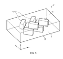
- FIG. 3 is a schematic representation of a composite structure with block arrays of reinforcing elements.
- FIG. 4 is a third angle projection of the structure of FIG. 3 .
- the present invention provides a composite component that includes through thickness reinforcement.
- the invention also provides a method that allows thick composite structures of a thickness greater than the maximum available reinforcing element length to be reinforced in the through thickness direction.
- the component and method of manufacture also provide a gradual transition from areas of no reinforcement to areas of full reinforcement within the component.
- FIGS. 3 and 4 illustrate a composite component according to the present invention.
- a composite component 2 comprises a primary structure 4 , formed from laminated layers of reinforcing fibres embedded in a surrounding matrix.
- the primary structure 4 defines a component thickness between planar upper and lower surfaces 8 , 10 of the component 2 , and a principal plane of the component, illustrated as the X-Y plane in the Figures.
- the through thickness direction of the component is the Z direction.
- the orientation of the reinforcing fibres within the layers of the primary structure may be along a primary axis x, a secondary axis y, or may be at varying angles with respect to the primary and secondary axes.
- Several layers having fibres of the same orientation may be blocked together, although in order to conform to relevant standards, it is envisaged that no more than four layers having fibres of the same orientation should be blocked together.
- the component 2 further comprises a plurality of block arrays of reinforcing elements, illustrated schematically at 6 on the Figures.
- the elements are illustrated in the Figures and described in the following disclosure as pins, however, it will be appreciated that the reinforcing elements may also comprise tufts of reinforcing material.
- Each block array 6 shown in the Figures comprises a regular array of reinforcing pins that is w pins wide, l pins long and has a depth in the direction of insertion equal to the length of the pins themselves.
- the block arrays 6 have been inserted into and extend through the primary structure 4 perpendicular to the principal plane X-Y of the primary structure 4 .
- the block arrays may be inserted at other angles with respect to the principal X-Y plane.
- the block arrays 6 extend through the primary structure 4 to the full depth of the arrays, that is the full length of the reinforcing pins, a surface of the arrays being level with the respective upper or lower surface of the component 2 .
- the component therefore includes arrays of reinforcing pins that extend their full length within the primary structure, at least partially through the thickness of the component.
- a number of the block arrays 6 have been inserted from, and thus extend from, the upper surface 8 of the component 2 , while the remaining block arrays 6 have been inserted from and extend from the lower surface 10 of the component 2 .
- the overlap region includes within it at least one change in fibre orientation between layers in the primary structure. The desired depth of the overlap region is thus determined by the number of layers of the same orientation that may be blocked together.
- the component is constructed to conform to a standard according to which no more than four layers having fibres of the same orientation may be blocked together. It is therefore envisaged that an overlap region having a depth o of 6 layers will be sufficient to ensure the overlap region includes at least one change of fibre orientation between layers.
- This limitation determines the maximum thickness of component 2 that may be formed according to a particular embodiment of the present invention.
- t max is the maximum thickness of composite component that may be constructed according to this embodiment
- L max is the maximum available length of the pins forming the arrays
- t ply is the cured thickness of each layer or ply forming the primary structure 4 of the component 2 .
- the maximum laminate thickness is 30.5 mm.
- the component further comprises at least one, and preferably at least one array, of intermediate reinforcing pins (or tufts of fibres).
- the array of intermediate reinforcing pins extends in the reinforcing direction through a region of the thickness of the component that is distant from both of the opposed component surfaces. The array of intermediate reinforcing pins is thus inserted during the lay up of the component, before the final component surfaces are formed. The array of intermediate reinforcing pins overlaps at each end in the reinforcing direction with other reinforcing elements.
- the intermediate reinforcing pin array(s) overlap in the reinforcement direction with the arrays 6 of reinforcing pins extending from each of the opposed component surfaces.
- arrays of intermediate reinforcing pins may overlap each other in the reinforcing direction, maintaining a continuous presence of reinforcing elements throughout the thickness of the component between the opposed component surfaces.
- t max n ⁇ L max ⁇ ( n ⁇ 1) ⁇ o ⁇ t ply
- n is the number of overlapping layers of reinforcing pins arrays
- o is the number of plies in each overlap region and t ply
- L max and t max are as above.
- An advantage of this embodiment is the ability to reinforce through the thickness of more complex shaped components.
- the introduction of intermediate block arrays facilitates the creation of more complex pinning combinations, allowing for through thickness reinforcement of a greater range of composite components. This also provides for increased freedom in the design process for composite components.
- This embodiment may also be used to advantage when it is desired for example to use shorter pins, or other reinforcing elements. It is commonly found that longer reinforcing pins are more difficult to drive into the uncured composite material, and that shorter reinforcing pins thus provide better mechanical performance.
- By employing intermediate array(s) of reinforcing pins a component of any given thickness may be reinforced through the complete component thickness using shorter reinforcing elements, facilitating insertion of these elements and allowing for improved mechanical performance.
- the block arrays 6 of reinforcing pins are angled with respect to the primary x axis of the component 2 .
- the long axis of the arrays 6 parallel to the long sides of length l, is angled at + or ⁇ 45 degrees to the primary axis x, and hence also to the secondary axis y.
- the arrays 6 are tessellated to form a herringbone pattern, as best seen in FIG. 4 .
- other arrangements or tessellations may also be employed.
- Arrays 6 that are adjacent on their long sides l have been inserted from, and thus extend from opposed surfaces, ensuring an even distribution of pin arrays 6 in the upper and lower halves of the component 2 .
- a similar arrangement may be employed including intermediate block arrays, ensuring even distribution of pin arrays throughout the component thickness.
- the angled orientation of the block arrays ensures that there is no straight line extending all the way through the pattern of reinforcement, there is no step change in the presence or absence of reinforcing elements along either the principle or secondary axes. This means that the component 2 does not experience a step change in structural properties along these axes, as would be caused by a sharp divide between regions provided with Z-direction reinforcement and regions without.
- the herringbone pattern provides for a “feathered” effect in which the transition between areas with and without Z-direction reinforcement is graduated.
- the angled arrays 6 may also be employed with all arrays 6 inserted from the same side, if the composite structure 2 is sufficiently thin to enable through thickness reinforcement to be achieved with a single pin length.
- the benefits afforded by the angled arrays are equally applicable to comparatively thin or thick composite structures.
- the present invention thus provides a component and method of construction that allows the reinforcement of thick composite laminates through their full thickness, where it would otherwise not be possible to use Z-direction reinforcing elements due to the limitation of maximum element length.
- This is achieved by alternately inserting adjacent arrays of elements from opposing surfaces of the composite structure, such that these elements extend from alternate sides in the finished component, preferably ensuring there is an overlap of reinforcing elements at the mid region.
- Intermediate arrays positioned within the thickness of the component and overlapping the arrays inserted from each opposing surface may also be included.
- the arrays are oriented, for example at 45 degrees, to the principal axis or laminate 0° direction.
- the resulting pattern may resemble a herringbone pattern. This pattern feathers the transition from areas with no reinforcing elements to areas of reinforcing elements, thus avoiding a step change in properties in the laminate.
- the present invention has been described with respect to a substantially uni directional, pre-preg composite laminate component. However, the present invention may also be applied to woven or other fabric pre-preg laminates, or other composite structures, to beneficial effect.
- the surface and intermediate reinforcement arrays, angled arrays and resulting herringbone or other pattern are not limited to pin reinforcement but may be used with tufting, stitching and 3D weaving. They may thus also be applied to dry preform, resin infusion type processes.
- the present invention may be employed in conjunction with all fibre types including for example carbon, glass, aramids, polymer and natural and in combination with any resin type.
Landscapes
- Engineering & Computer Science (AREA)
- Chemical & Material Sciences (AREA)
- Materials Engineering (AREA)
- Mechanical Engineering (AREA)
- Composite Materials (AREA)
- General Engineering & Computer Science (AREA)
- Moulding By Coating Moulds (AREA)
- Laminated Bodies (AREA)
Applications Claiming Priority (2)
| Application Number | Priority Date | Filing Date | Title |
|---|---|---|---|
| GB201111598A GB201111598D0 (en) | 2011-07-07 | 2011-07-07 | Layered composite component |
| GB1111598.7 | 2011-07-07 |
Publications (2)
| Publication Number | Publication Date |
|---|---|
| US20130011625A1 US20130011625A1 (en) | 2013-01-10 |
| US8808847B2 true US8808847B2 (en) | 2014-08-19 |
Family
ID=44544344
Family Applications (1)
| Application Number | Title | Priority Date | Filing Date |
|---|---|---|---|
| US13/525,821 Active US8808847B2 (en) | 2011-07-07 | 2012-06-18 | Layered composite component |
Country Status (5)
| Country | Link |
|---|---|
| US (1) | US8808847B2 (fr) |
| EP (2) | EP2543506B1 (fr) |
| CN (1) | CN102862299B (fr) |
| CA (1) | CA2780574C (fr) |
| GB (1) | GB201111598D0 (fr) |
Cited By (1)
| Publication number | Priority date | Publication date | Assignee | Title |
|---|---|---|---|---|
| US20160076552A1 (en) * | 2014-09-16 | 2016-03-17 | General Electric Company | Composite airfoil structures |
Families Citing this family (4)
| Publication number | Priority date | Publication date | Assignee | Title |
|---|---|---|---|---|
| GB201511686D0 (en) * | 2015-07-03 | 2015-08-19 | Rolls Royce Plc | Composite component |
| DK3990247T3 (da) * | 2019-06-26 | 2025-01-13 | Nano Dimension Tech Ltd | Additiv fremstilling af forbedret termomekanisk kompositmateriale |
| GB202118072D0 (en) * | 2021-12-14 | 2022-01-26 | Rolls Royce Plc | A rotatable aerofoil component with z-pins |
| US12523390B2 (en) * | 2022-12-23 | 2026-01-13 | GM Global Technology Operations LLC | Adaptive duct |
Citations (18)
| Publication number | Priority date | Publication date | Assignee | Title |
|---|---|---|---|---|
| US3602608A (en) | 1968-08-01 | 1971-08-31 | Rolls Royce | Composite blade |
| GB1245342A (en) | 1969-04-01 | 1971-09-08 | Rolls Royce | Method and apparatus for making a fibre-reinforced article |
| GB1305755A (fr) | 1969-04-24 | 1973-02-07 | ||
| US3834832A (en) | 1971-12-21 | 1974-09-10 | Rolls Royce 1971 Ltd | Fibre reinforced composite structures |
| GB1411484A (en) | 1972-09-07 | 1975-10-29 | Transco Inc | Heat and sound insulating panel |
| US4808461A (en) | 1987-12-14 | 1989-02-28 | Foster-Miller, Inc. | Composite structure reinforcement |
| GB2227205A (en) | 1988-11-25 | 1990-07-25 | David Richard Painter | Laminated panels for vaults |
| GB2261589A (en) | 1991-11-23 | 1993-05-26 | Dowty Armourshield Ltd | Armour |
| US5308228A (en) | 1991-12-04 | 1994-05-03 | Societe Nationale d'Etude et de Construction de Moteurs d`Aviation "S.N.E.C.M.A." | Gas turbine blade comprising layers of composite material |
| US5375978A (en) | 1992-05-01 | 1994-12-27 | General Electric Company | Foreign object damage resistant composite blade and manufacture |
| WO1998004495A1 (fr) | 1996-07-26 | 1998-02-05 | Cascade Engineering, Inc. | Systeme et procede de fixation d'une couche isolante sur un materiau en feuille |
| US5876540A (en) | 1996-05-31 | 1999-03-02 | The Boeing Company | Joining composites using Z-pinned precured strips |
| US20020160146A1 (en) | 2000-02-28 | 2002-10-31 | Kiyoshi Homma | Multiaxially stitched base material for reinforcing and fiber reinforced plastic, and method for preparing them |
| US6481172B1 (en) | 2000-01-12 | 2002-11-19 | William H. Porter | Structural wall panels |
| US20030203179A1 (en) | 2001-07-18 | 2003-10-30 | Hawkins James Thomas | Pin reinforced, crack resistant fiber reinforced composite article and method for making |
| US20080193709A1 (en) | 2006-10-27 | 2008-08-14 | Nanlin Han | Fiber Products, Prepregs, Composites and Method of Producing Same |
| US7547194B2 (en) * | 2006-07-31 | 2009-06-16 | General Electric Company | Rotor blade and method of fabricating the same |
| US20110070092A1 (en) * | 2009-09-24 | 2011-03-24 | Rolls-Royce Plc | Hybrid component |
Family Cites Families (3)
| Publication number | Priority date | Publication date | Assignee | Title |
|---|---|---|---|---|
| US5466506A (en) * | 1992-10-27 | 1995-11-14 | Foster-Miller, Inc. | Translaminar reinforcement system for Z-direction reinforcement of a fiber matrix structure |
| US6613392B2 (en) * | 2001-07-18 | 2003-09-02 | General Electric Company | Method for making a fiber reinforced composite article and product |
| GB0715164D0 (en) * | 2007-08-06 | 2007-09-12 | Airbus Uk Ltd | Method and apparatus for manufacturing a composite material |
-
2011
- 2011-07-07 GB GB201111598A patent/GB201111598D0/en not_active Ceased
-
2012
- 2012-06-18 EP EP12172353.0A patent/EP2543506B1/fr not_active Not-in-force
- 2012-06-18 EP EP16187348.4A patent/EP3127697B1/fr active Active
- 2012-06-18 US US13/525,821 patent/US8808847B2/en active Active
- 2012-06-19 CA CA2780574A patent/CA2780574C/fr active Active
- 2012-07-06 CN CN201210233115.6A patent/CN102862299B/zh not_active Expired - Fee Related
Patent Citations (20)
| Publication number | Priority date | Publication date | Assignee | Title |
|---|---|---|---|---|
| US3602608A (en) | 1968-08-01 | 1971-08-31 | Rolls Royce | Composite blade |
| GB1245342A (en) | 1969-04-01 | 1971-09-08 | Rolls Royce | Method and apparatus for making a fibre-reinforced article |
| GB1305755A (fr) | 1969-04-24 | 1973-02-07 | ||
| US3834832A (en) | 1971-12-21 | 1974-09-10 | Rolls Royce 1971 Ltd | Fibre reinforced composite structures |
| GB1411484A (en) | 1972-09-07 | 1975-10-29 | Transco Inc | Heat and sound insulating panel |
| US4808461A (en) | 1987-12-14 | 1989-02-28 | Foster-Miller, Inc. | Composite structure reinforcement |
| GB2227205A (en) | 1988-11-25 | 1990-07-25 | David Richard Painter | Laminated panels for vaults |
| GB2261589A (en) | 1991-11-23 | 1993-05-26 | Dowty Armourshield Ltd | Armour |
| US5308228A (en) | 1991-12-04 | 1994-05-03 | Societe Nationale d'Etude et de Construction de Moteurs d`Aviation "S.N.E.C.M.A." | Gas turbine blade comprising layers of composite material |
| US5375978A (en) | 1992-05-01 | 1994-12-27 | General Electric Company | Foreign object damage resistant composite blade and manufacture |
| US6436507B1 (en) * | 1996-05-31 | 2002-08-20 | The Boeing Company | Composites joined with z-pin reinforcement |
| US5876540A (en) | 1996-05-31 | 1999-03-02 | The Boeing Company | Joining composites using Z-pinned precured strips |
| WO1998004495A1 (fr) | 1996-07-26 | 1998-02-05 | Cascade Engineering, Inc. | Systeme et procede de fixation d'une couche isolante sur un materiau en feuille |
| US6481172B1 (en) | 2000-01-12 | 2002-11-19 | William H. Porter | Structural wall panels |
| US20020160146A1 (en) | 2000-02-28 | 2002-10-31 | Kiyoshi Homma | Multiaxially stitched base material for reinforcing and fiber reinforced plastic, and method for preparing them |
| US20030203179A1 (en) | 2001-07-18 | 2003-10-30 | Hawkins James Thomas | Pin reinforced, crack resistant fiber reinforced composite article and method for making |
| US7008689B2 (en) | 2001-07-18 | 2006-03-07 | General Electric Company | Pin reinforced, crack resistant fiber reinforced composite article |
| US7547194B2 (en) * | 2006-07-31 | 2009-06-16 | General Electric Company | Rotor blade and method of fabricating the same |
| US20080193709A1 (en) | 2006-10-27 | 2008-08-14 | Nanlin Han | Fiber Products, Prepregs, Composites and Method of Producing Same |
| US20110070092A1 (en) * | 2009-09-24 | 2011-03-24 | Rolls-Royce Plc | Hybrid component |
Non-Patent Citations (2)
| Title |
|---|
| Oct. 11, 2011 British Search Report issued in British Patent Application No. GB1111598.7. |
| Sep. 27, 2012 Search Report issued in European Patent Application No. 12 17 2353. |
Cited By (2)
| Publication number | Priority date | Publication date | Assignee | Title |
|---|---|---|---|---|
| US20160076552A1 (en) * | 2014-09-16 | 2016-03-17 | General Electric Company | Composite airfoil structures |
| US10099434B2 (en) * | 2014-09-16 | 2018-10-16 | General Electric Company | Composite airfoil structures |
Also Published As
| Publication number | Publication date |
|---|---|
| GB201111598D0 (en) | 2011-08-24 |
| CN102862299A (zh) | 2013-01-09 |
| CA2780574C (fr) | 2019-06-11 |
| CN102862299B (zh) | 2017-03-01 |
| EP3127697A1 (fr) | 2017-02-08 |
| EP2543506A1 (fr) | 2013-01-09 |
| EP2543506B1 (fr) | 2017-05-17 |
| EP3127697B1 (fr) | 2020-03-18 |
| US20130011625A1 (en) | 2013-01-10 |
| CA2780574A1 (fr) | 2013-01-07 |
Similar Documents
| Publication | Publication Date | Title |
|---|---|---|
| US8357323B2 (en) | Ceramic matrix composite wall with post laminate stitching | |
| US10590945B2 (en) | Fiber composite material and preform and fan blade made therefrom | |
| EP2415585B1 (fr) | Anneau de rétention en matériau composite pour une turbomachine | |
| US5279892A (en) | Composite airfoil with woven insert | |
| US20110176927A1 (en) | Composite fan blade | |
| JP5406850B2 (ja) | 交差壁を伴う閉じ構造を織る方法 | |
| US8685868B2 (en) | Reinforcing fibrous structure for a composite material and a part containing said structure | |
| US10099434B2 (en) | Composite airfoil structures | |
| CN104349888A (zh) | 具有低密度芯部和复合缝合加强件的复合结构 | |
| Wambua et al. | A review of preforms for the composites industry | |
| CN101918630A (zh) | 用于复合结构应用的混杂三维织造/层合支撑物 | |
| CN102648080B (zh) | 编织预制件、复合材料、及其制造方法 | |
| US20220403748A1 (en) | Woven fibrous preform for manufacturing a fan blade made of composite material | |
| US20160031182A1 (en) | Composite flange with three-dimensional weave architecture | |
| CA2866029A1 (fr) | Entretoises tridimensionnelles hybrides tissees ou stratifiees pour elements structurels composites | |
| CA2780574C (fr) | Element composite en couches | |
| US9962901B2 (en) | Preform with integrated gap fillers | |
| CN102666050A (zh) | 编织预制件、复合材料、及其制造方法 | |
| EP3018293A1 (fr) | Composant en matière composite avec noyau renforcé en fibre | |
| US20030203179A1 (en) | Pin reinforced, crack resistant fiber reinforced composite article and method for making | |
| CN115431553A (zh) | 包含增强纤维和形状记忆合金线的产品及其制备方法 | |
| CN104448877B (zh) | 包括分散的纤维丝的复合织物 | |
| CN119305265A (zh) | 一种具有层间波锁结构的纤维树脂基复合材料及其制备方法 | |
| Deshpande et al. | Recent trends and developments in the use of woven fabric reinforcements for composite materials | |
| CN111549421A (zh) | 一种仿生钩连结构三维编织预浸件 |
Legal Events
| Date | Code | Title | Description |
|---|---|---|---|
| AS | Assignment |
Owner name: ROLLS-ROYCE PLC, GREAT BRITAIN Free format text: ASSIGNMENT OF ASSIGNORS INTEREST;ASSIGNORS:JEVONS, MATTHEW PAUL;BACKHOUSE, ROBERT;REEL/FRAME:028417/0254 Effective date: 20120613 |
|
| STCF | Information on status: patent grant |
Free format text: PATENTED CASE |
|
| MAFP | Maintenance fee payment |
Free format text: PAYMENT OF MAINTENANCE FEE, 4TH YEAR, LARGE ENTITY (ORIGINAL EVENT CODE: M1551) Year of fee payment: 4 |
|
| MAFP | Maintenance fee payment |
Free format text: PAYMENT OF MAINTENANCE FEE, 8TH YEAR, LARGE ENTITY (ORIGINAL EVENT CODE: M1552); ENTITY STATUS OF PATENT OWNER: LARGE ENTITY Year of fee payment: 8 |
|
| MAFP | Maintenance fee payment |
Free format text: PAYMENT OF MAINTENANCE FEE, 12TH YEAR, LARGE ENTITY (ORIGINAL EVENT CODE: M1553); ENTITY STATUS OF PATENT OWNER: LARGE ENTITY Year of fee payment: 12 |