US881143A - Device for replacing fusible plugs. - Google Patents
Device for replacing fusible plugs. Download PDFInfo
- Publication number
- US881143A US881143A US37401707A US1907374017A US881143A US 881143 A US881143 A US 881143A US 37401707 A US37401707 A US 37401707A US 1907374017 A US1907374017 A US 1907374017A US 881143 A US881143 A US 881143A
- Authority
- US
- United States
- Prior art keywords
- tube
- boiler
- plug
- steam
- bushing
- Prior art date
- Legal status (The legal status is an assumption and is not a legal conclusion. Google has not performed a legal analysis and makes no representation as to the accuracy of the status listed.)
- Expired - Lifetime
Links
- XLYOFNOQVPJJNP-UHFFFAOYSA-N water Substances O XLYOFNOQVPJJNP-UHFFFAOYSA-N 0.000 description 6
- 238000004140 cleaning Methods 0.000 description 2
- 238000010276 construction Methods 0.000 description 2
- 235000015700 Artemisia abrotanum Nutrition 0.000 description 1
- 244000249062 Artemisia abrotanum Species 0.000 description 1
- ATJFFYVFTNAWJD-UHFFFAOYSA-N Tin Chemical compound [Sn] ATJFFYVFTNAWJD-UHFFFAOYSA-N 0.000 description 1
- 230000006978 adaptation Effects 0.000 description 1
- 238000007664 blowing Methods 0.000 description 1
- 238000004880 explosion Methods 0.000 description 1
- 210000004907 gland Anatomy 0.000 description 1
- 230000002452 interceptive effect Effects 0.000 description 1
- 239000000155 melt Substances 0.000 description 1
- 239000002184 metal Substances 0.000 description 1
- 238000012856 packing Methods 0.000 description 1
Images
Classifications
-
- F—MECHANICAL ENGINEERING; LIGHTING; HEATING; WEAPONS; BLASTING
- F22—STEAM GENERATION
- F22B—METHODS OF STEAM GENERATION; STEAM BOILERS
- F22B37/00—Component parts or details of steam boilers
- F22B37/02—Component parts or details of steam boilers applicable to more than one kind or type of steam boiler
- F22B37/42—Applications, arrangements or dispositions of alarm or automatic safety devices
- F22B37/47—Applications, arrangements or dispositions of alarm or automatic safety devices responsive to abnormal temperature, e.g. actuated by fusible plugs
- F22B37/475—Safety devices with fusible plugs
Definitions
- This invention relates to an improved device for replacing fusible plugs in steam boilers, and the object of the invention is to provide means for cleaning the plug seat and inserting a new plug without drawing the fire, in case the water in the boiler should get low enough to increase the heat sufliciently to melt the original plug.
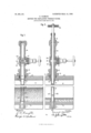
- Figure 1 is a fragmentary section through a steam boiler equipped with the improved fusible plug replacing device, showing a cen tral longitudinal section through the device.
- Fig. 2 is a similar view showing the reamer in position to clean the plug seat.
- a bushing 1 is screwed into the crown sheet 2, of the boiler in the usual man ner and position.
- This bushing 1 has an F opening 3, in which a fusible plug or bank of tin 4, is inserted.
- the opening 3' is tapered so as to be narrower at the bottom than at the top, and the fusible plug 4, is tapered in like manner so as to fit tightly in the opening, as shown in Fig. 1.
- a tube 5 has its lower end screwed into the upper portion of the bushing 1, and extends vertically upward through the steam and water space 6.
- a stufling box 9 is screwed into the boiler shell 8, and the tube 7, passed therethrough in the manner shown in the drawings.
- a gland 10 encircles the tube 7, and screws into the stuffing box by means of which the packing 11, may be compressed.
- the lower end of the tube is provided with an annular flange 12 of sufficient size to prevent the passage of the tube through the stuffing box.
- a valve 13 is screwed upon the upper end of the short tube 7, and another tubular part 14, is screwed into the opposite side of the valve 13, so as to be in vertical alinement with the tubes 7 and 5, and the bushing 1.
- the upper end of the tube 14, is enlarged and internally screw threaded, and a stufling box 15, has a reduced lower portion 16, which screws into the screw threaded upper end of the tube 14, see Fig. 2.
- the valve 13 is preferably of the kind commonly termed a gate valve, and'has a screw threaded stem 17, on the inner end of which are two disis 18 and 19, which engage with upper and lower seats 20 and 21.
- a gate valve preferably of the kind commonly termed a gate valve
- the valve 13 has a screw threaded stem 17, on the inner end of which are two disis 18 and 19, which engage with upper and lower seats 20 and 21.
- a reamer 22 is provided, being formed integrally at the lower end of a rod 23, which has a hand wheel 24, at its upper end. This reamer is used to clean out the opening 3, in the bushing 1, before inserting a fusible plug therein.
- the tube 5 has a series of slots 25, near its lower end through which the steam enters the tube.
- the device is as shown in Fig. 1, the opening 3, in the bushing 1, being filled with a fusible plug 4, of suitable metal, and the gate valve 13, closed. Should the water in the boiler get low, the heat melts the fusible plug 4, and the steam passing through the opening 3, enters the fire box and deadens the fire. When this occurs the attendant immediately inserts the reamer 22, into the tube 14, screws the stufiing box 15, firmly into the upper-end of said tube and then opens the gate valve 13, thereby permitting the reamer 22, to pass through the tubes 7, and 5 into the opening 3, in the bushing 1.
- the reamer is now rotated by means of the hand wheel 24, at the upper end of the rod 23, until the opening 3, is cleansed of all residue of the melted plug.
- the reamer 22, is now withdrawn into the tube 14, and the gate valve 13, closed to prevent the escape of steam.
- the stuffing box 15, is now unscrewed and the reamer 22', withdrawn from the tube 14, in which a new fusible plug is inserted.
- the reamer 22, is now again inserted in the tube 14 and the stuffing box 15, screwed into place.
- the valve 13, is now opened and the fusible plug descends through the tubes 7 and 5, and finds its seat in the bushing 1.
- the reamer can be used to tap the plug lightly into the opening 3.
- the reamer is now withdrawn into the tube 14 and the valve 13, closed.
- the stuffing box 15, is now unscrewed and with the reamer 22, is removed from the tube 14.
- the purpose of the flange 12, on the lower end of the tube 7, is to prevent the steam pressure in the boiler from blowing the tube 7 through the stufiing box 9, in case the tube 5, should be broken in any way.
- the fusible plug can be quickly replaced without throwing the boiler out of commission, or in any way endangering the attendant by drawing the fire while steam is entering the fire box.
Landscapes
- Engineering & Computer Science (AREA)
- Physics & Mathematics (AREA)
- Thermal Sciences (AREA)
- Mechanical Engineering (AREA)
- General Engineering & Computer Science (AREA)
- Details Of Valves (AREA)
Description
PATENTED MAR. '10, 1908.
E. OLDMAN. DEVICE FOR REPLAGING FUSIBLE PLUGS.
APPLICATION IILBD MAY 16. 1907.
Fig. 2.
lil XII/7 el/rand aid/232? z; j Attorney.
Witnesses. 0% KM EDWARD OLDMAN, OF BUFFALO, NEW YORK.
DEVICE FOR REPLACING FUSIBLE PLUGS.
Specification of Letters Patent.
Patented March 10, 1908.
Application filed May 16, 1907. Serial No. 374,017.
To all whom it may concern:
Be it known that I, EDWARD OLDMAN, a citizen of the United States, residing at Buffalo, in the county of Erie and State of New York, have invented certain new and useful Improvements in Devices for Replacing Fusible Plugs, of which the following is a specification.
This invention relates to an improved device for replacing fusible plugs in steam boilers, and the object of the invention is to provide means for cleaning the plug seat and inserting a new plug without drawing the fire, in case the water in the boiler should get low enough to increase the heat sufliciently to melt the original plug.
The invention also relates to certain details of construction, all of which will be fully and clearly hereinafter described and claimed reference being had to the accompanying drawings, in which,
Figure 1 is a fragmentary section through a steam boiler equipped with the improved fusible plug replacing device, showing a cen tral longitudinal section through the device. Fig. 2 is a similar view showing the reamer in position to clean the plug seat.
In referring to the drawings for the details of construction, like numerals designate like parts.
It is the practice in constructing steam boilers, and especially marine boilers, to place a fusible plug in the crown sheet, which meltswhen the water in the boiler gets low, and permits steam to enter the fire box and deaden the fire, thereby preventing the explosion of the boiler. Heretofore when this occurred, it has been necessary to draw the fire, at great risk to the stoker from the steam entering thefire box, allow the boiler to cool, then enter the boiler and remove the bushing in which the fusible plug is seated. After cleaning the plug seat and inserting a new plug, the whole must be replaced in the crown sheet. By means of this invention, however, the plug seat can be cleaned and a new plug inserted without in any way interfering with the fire or the use of the boiler.
In the preferred adaptation of the invention as illustrated in the accompanying drawings, a bushing 1, is screwed into the crown sheet 2, of the boiler in the usual man ner and position. This bushing 1, has an F opening 3, in which a fusible plug or bank of tin 4, is inserted. The opening 3', is tapered so as to be narrower at the bottom than at the top, and the fusible plug 4, is tapered in like manner so as to fit tightly in the opening, as shown in Fig. 1.
A tube 5, has its lower end screwed into the upper portion of the bushing 1, and extends vertically upward through the steam and water space 6. The upper end of this tube 5, screws into the lower end of a short tube 7, which extends through the boiler shell 8.
To provide a steam tight joint between the tube 7, and the boiler shell 8, and also allow for the expansion of the tubes, a stufling box 9, is screwed into the boiler shell 8, and the tube 7, passed therethrough in the manner shown in the drawings. A gland 10, encircles the tube 7, and screws into the stuffing box by means of which the packing 11, may be compressed. The lower end of the tube is provided with an annular flange 12 of sufficient size to prevent the passage of the tube through the stuffing box.
A valve 13, is screwed upon the upper end of the short tube 7, and another tubular part 14, is screwed into the opposite side of the valve 13, so as to be in vertical alinement with the tubes 7 and 5, and the bushing 1.
The upper end of the tube 14, is enlarged and internally screw threaded, and a stufling box 15, has a reduced lower portion 16, which screws into the screw threaded upper end of the tube 14, see Fig. 2.
The valve 13, is preferably of the kind commonly termed a gate valve, and'has a screw threaded stem 17, on the inner end of which are two disis 18 and 19, which engage with upper and lower seats 20 and 21. When the disfs 18 and 19, are in engagement with the seats 20 and 21, communication between the tubes 14 and 7, is closed as shown in Fig. 1.
A reamer 22, is provided, being formed integrally at the lower end of a rod 23, which has a hand wheel 24, at its upper end. This reamer is used to clean out the opening 3, in the bushing 1, before inserting a fusible plug therein.
The tube 5, has a series of slots 25, near its lower end through which the steam enters the tube.
The operation of the device is as follows, normally, the device is as shown in Fig. 1, the opening 3, in the bushing 1, being filled with a fusible plug 4, of suitable metal, and the gate valve 13, closed. Should the water in the boiler get low, the heat melts the fusible plug 4, and the steam passing through the opening 3, enters the fire box and deadens the fire. When this occurs the attendant immediately inserts the reamer 22, into the tube 14, screws the stufiing box 15, firmly into the upper-end of said tube and then opens the gate valve 13, thereby permitting the reamer 22, to pass through the tubes 7, and 5 into the opening 3, in the bushing 1. The reamer is now rotated by means of the hand wheel 24, at the upper end of the rod 23, until the opening 3, is cleansed of all residue of the melted plug. The reamer 22, is now withdrawn into the tube 14, and the gate valve 13, closed to prevent the escape of steam. The stuffing box 15, is now unscrewed and the reamer 22', withdrawn from the tube 14, in which a new fusible plug is inserted. As the gate valve 13, is closed, it blocks the passage of the plug. The reamer 22, is now again inserted in the tube 14 and the stuffing box 15, screwed into place. The valve 13, is now opened and the fusible plug descends through the tubes 7 and 5, and finds its seat in the bushing 1. The reamer can be used to tap the plug lightly into the opening 3. The reamer is now withdrawn into the tube 14 and the valve 13, closed. The stuffing box 15, is now unscrewed and with the reamer 22, is removed from the tube 14.
The purpose of the flange 12, on the lower end of the tube 7, is to prevent the steam pressure in the boiler from blowing the tube 7 through the stufiing box 9, in case the tube 5, should be broken in any way.
By the aid of this improved device the fusible plug can be quickly replaced without throwing the boiler out of commission, or in any way endangering the attendant by drawing the fire while steam is entering the fire box.
I claim as my invention.
1. The combination with a boiler and its crown sheet, of a bushing fitted in an opening in the crown sheet and a slotted lower tube having its lower end screwed into the bushing and extending through the steam and water space of the boiler, an intermediate tube screwed to the low er tube and extending through a stuffing box in the boiler shell, an upper tube arranged vertically above the intermediate tube, a valve located between the intermediate tube and the upper tube for closing communication between them, and means for preventing the passage of the intermediate tube through the boiler shellin one direction, substantially as described.
2. The combination with a boiler and its crown sheet, of a bushing fitted in an opening in the crown sheet and constituting a plug seat, a slotted lower tube having its lower end screwed into the bushing and extending through the steam and water space of the boiler, an intermediate tube screwed to the lower tube and extending through a stuffing box in the boiler shell, an upper tube arranged vertically above the intermediate tube, a valve located between the intermediate tube and the upper tube for closing communication between them, and a flange on the intermediate tube for preventing its passage through the stufIing box in an outward direction, substantially as described.
EDWARD OLDMAN.
Witnesses:
L. M. SANesTER, FREDERICK P. DUOHSOHERER.
Priority Applications (1)
| Application Number | Priority Date | Filing Date | Title |
|---|---|---|---|
| US37401707A US881143A (en) | 1907-05-16 | 1907-05-16 | Device for replacing fusible plugs. |
Applications Claiming Priority (1)
| Application Number | Priority Date | Filing Date | Title |
|---|---|---|---|
| US37401707A US881143A (en) | 1907-05-16 | 1907-05-16 | Device for replacing fusible plugs. |
Publications (1)
| Publication Number | Publication Date |
|---|---|
| US881143A true US881143A (en) | 1908-03-10 |
Family
ID=2949583
Family Applications (1)
| Application Number | Title | Priority Date | Filing Date |
|---|---|---|---|
| US37401707A Expired - Lifetime US881143A (en) | 1907-05-16 | 1907-05-16 | Device for replacing fusible plugs. |
Country Status (1)
| Country | Link |
|---|---|
| US (1) | US881143A (en) |
-
1907
- 1907-05-16 US US37401707A patent/US881143A/en not_active Expired - Lifetime
Similar Documents
| Publication | Publication Date | Title |
|---|---|---|
| US195367A (en) | Improvement in fusible plugs for steam-generators | |
| ES2095637T3 (en) | INSTALLATION OF SAFETY AGAINST FAILURE OF A NUCLEAR REACTOR PRESSURE BOILER DUE TO OVERPRESSURE. | |
| US881143A (en) | Device for replacing fusible plugs. | |
| US685561A (en) | Flue-plug for boilers. | |
| US2216351A (en) | Blowout plug | |
| US989901A (en) | Fusible plug. | |
| US960944A (en) | Water-gage. | |
| US708562A (en) | Emergency safety-plug. | |
| US967416A (en) | Twyer for blast-furnaces. | |
| US1000108A (en) | Service-box section. | |
| US924207A (en) | Valve. | |
| US1172977A (en) | Cut-off for conduits. | |
| US506564A (en) | stulp | |
| US1016026A (en) | Pipe-tapping means. | |
| US1011236A (en) | Stuffing-box for polished rods for oil-wells. | |
| US1284833A (en) | Valve. | |
| US2069588A (en) | Valve | |
| US901142A (en) | Soft-plug valve. | |
| US766606A (en) | Fusible-plug valve. | |
| US760126A (en) | Steam-boiler. | |
| US859441A (en) | Valve. | |
| US862741A (en) | Blow-off valve. | |
| US1118613A (en) | Twyer-valve. | |
| US1837542A (en) | Device for controlling the flow of oil and gas from wells | |
| US161422A (en) | Improvement in fusible plugs for steam-generators |