US8821501B2 - Patella resectioning guide and assembly - Google Patents
Patella resectioning guide and assembly Download PDFInfo
- Publication number
- US8821501B2 US8821501B2 US13/176,802 US201113176802A US8821501B2 US 8821501 B2 US8821501 B2 US 8821501B2 US 201113176802 A US201113176802 A US 201113176802A US 8821501 B2 US8821501 B2 US 8821501B2
- Authority
- US
- United States
- Prior art keywords
- arm
- pivot axis
- resection guide
- bone
- gripping member
- Prior art date
- Legal status (The legal status is an assumption and is not a legal conclusion. Google has not performed a legal analysis and makes no representation as to the accuracy of the status listed.)
- Expired - Fee Related, expires
Links
Images




Classifications
-
- A—HUMAN NECESSITIES
- A61—MEDICAL OR VETERINARY SCIENCE; HYGIENE
- A61B—DIAGNOSIS; SURGERY; IDENTIFICATION
- A61B17/00—Surgical instruments, devices or methods
- A61B17/14—Surgical saws
- A61B17/15—Guides therefor
- A61B17/154—Guides therefor for preparing bone for knee prosthesis
- A61B17/158—Cutting patella
Definitions
- the present disclosure relates generally to orthopaedic surgical instruments and more particularly to patella resectioning guides and styluses.
- Joint arthroplasty is a well-known surgical procedure by which a diseased and/or damaged natural joint is replaced by a prosthetic joint.
- a typical knee prosthesis includes a tibial tray, a femoral component, and a polymer insert or bearing positioned between the tibial tray and the femoral component.
- the knee prosthesis may also include a prosthetic patella component, which is secured to a posterior side of the patient's surgically-prepared patella. To do so, an orthopaedic surgeon may resect the posterior dome side of the patient's natural patella to secure the prosthetic component thereto.
- the patella component articulates with the patient's natural or prosthetic femur during extension and flexion of the patient's knee.
- orthopaedic surgeons use a variety of orthopaedic surgical instruments such as, for example, cutting blocks, drill guides, milling guides, and other surgical instruments.
- orthopaedic surgical instruments are generic with respect to the patient such that the same orthopaedic surgical instrument may be used on a number of different patients during similar orthopaedic surgical procedures.
- native patellae are of substantially different sizes. Accordingly, if a resection guide is to be used, either the guide must be provided in a plurality of sizes to accommodate variations in patellae size or an adjustable resection guide must be used.
- the present invention provides a patella resection guide that assists the surgeon in performing a guided resection that ensures that the patella implant is properly positioned and that an appropriate amount of bone remains after resection.
- the present invention provides a patella resection guide comprising a first arm, a second arm, a connecting member, and a cooperative locking mechanism associated with the first and second arms for releasably locking the arms in a desired position.
- Each arm has a first end, a second end spaced from the first end, a first portion extending from the first end and a second portion extending from the second end toward the first portion.
- the first end of the first arm is pivotably connected to the connecting member about a first pivot axis.
- the first end of the second arm is pivotably connected to the connecting member about a second pivot axis.
- the first portion of the first arm is pivotably connected to the second portion of the first arm about a third pivot axis.
- the first portion of the second arm is pivotably connected to the second portion of the second arm about a fourth pivot axis.
- the first, second, third and fourth pivot axes are parallel to each other.
- the first portion of the first arm includes a first bone gripping member extending toward the first portion of the second arm and the first portion of the second arm includes a second bone gripping member extending toward the first portion of the first arm.
- the first bone-gripping member and second bone-gripping member lie in a plane that is substantially perpendicular to the first pivot axis, second pivot axis, third pivot axis and fourth pivot axis and define a space therebetween to receive a patella.
- the first bone-gripping member and the second bone-gripping member are spaced apart by a distance.
- the first arm includes a first flat and planar resection guide surface substantially parallel to the plane of the first bone-gripping member.
- the second arm also includes a second flat and planar resection guide surface substantially parallel to the plane of the first bone-gripping member.
- the ratchet includes an end fixed to the first arm at a position between the third pivot axis and the second end of the first arm.
- the second arm includes a ratchet slot positioned between the fourth pivot axis and the second end of the second arm. The ratchet extends from the first arm through the ratchet slot in the second arm.
- Pivoting the portions of the first and second arms about the first pivot axis, second pivot axis, third pivot axis and fourth pivot axis move the first bone-gripping member and second bone-gripping member toward and away from each other to vary the distance between the first bone-gripping member and the second bone-gripping member.
- the ratchet locking plate is fixed to the second arm and includes a locking member movable to selectively engage the ratchet to fix the position of the first bone-gripping member with respect to the second bone-gripping member.
- the second end of the first arm may be pivotably connected to the second end of the second arm about a fifth pivot axis that is parallel to the first pivot axis, second pivot axis, third pivot axis and fourth pivot axis.
- the connections defining all or some of the first pivot axis, second pivot axis, third pivot axis, fourth pivot axis and fifth pivot axis may comprise living hinges.
- the second portion of the first arm and second portion of the second arm may include surfaces defining paddles for gripping to close the resection guide. These surfaces defining the paddles may be flat or have curved contours (convex or concave).
- the first planar resection guide surface may be co-planar with the second planar resection guide surface.
- the first arm, the second arm and connecting member may comprise a unitary polymer base.
- the first planar resection guide surface and second planar guide surface may be parts of elements distinct from and connected to the base.
- the resection guide may further comprise a first plate and a second plate; the first plate may be mounted to the base and positioned parallel to and spaced from the first planar resection guide surface to define a first guide slot and the second plate may be mounted to the base and positioned parallel to and spaced from the second planar resection guide surface to define a second guide slot.
- the base may extend from the first end to the second end of the first arm and from the first end to the second end of the second arm.
- the first plate may be pivotably connected to the base and the second plate may be pivotably connected to the base.
- first planar resection guide surface and second planar resection guide surface may comprise channel members extending around part of the base and defining the first and second bone-gripping members.
- the patella resection guide may be part of a patella resection kit further comprising a stylus.
- the connecting member may include an upstanding portion defining a through-slot.
- the second portion of the first arm may include a first upstanding boss having a central longitudinal axis parallel to the first pivot axis, second pivot axis, third pivot axis and fourth pivot axis and the second portion of the second arm may include a second upstanding boss having a central longitudinal axis parallel to the first pivot axis, second pivot axis, third pivot axis and fourth pivot axis.
- a stylus in such a kit may include an elongate member having parallel first and second edges, a free first end and a second end, a thinner portion at the free first end and a cross-member at the second end of the elongate member.
- the cross-member may have a first end and a second end, a central portion connected to the second end of the elongate member, a first end portion at the first end and a second end portion at the second end.
- the first end portion of the cross-member may be pivotably connected to the central portion about a sixth pivot axis
- the second end portion of the cross-member may be pivotably connected to the central portion about a seventh pivot axis.
- the first end portion of the cross-member includes a first mounting member and the second end portion of the cross-member includes a second mounting member, the first mounting member and the second mounting member serving to selectively and removably mount the cross-member to the first boss and the second boss of the resection guide.
- the stylus is selectively and removably assembled with the resection guide with the thinner portion at the free first end of the elongate member received in the slot in the upstanding portion of the connecting member and the first mounting member and second mounting member engaging the first boss and the second boss.
- Pivoting the portions of the first arm and second arm of the resection guide about the first pivot axis, second pivot axis, third pivot axis and fourth pivot axis to move the first bone-gripping member and second bone-gripping member toward and away from each other causes the end portions of the styles to pivot with respect to the cross-member and the thinner portion of the elongate member of the stylus to move longitudinally in the through-slot of the upstanding member of the resection guide.
- the first and second edges of the elongate member of the stylus are parallel to the plane of the first and second resection guide surfaces of the resection guide.
- the stylus and resection guide can be assembled with the stylus being in one of two orientations.
- a first orientation the thinner portion at the free first end of the elongate member is received in the slot in the upstanding portion of the connecting member, the first mounting member and second mounting member engage the first boss and the second boss, and the first edge of the elongate member is nearest the plane of the first and second resection guide surfaces; in this orientation, the distance between the first edge and the plane of the first and second resection guide surfaces is a predetermined first distance.
- the thinner portion at the free first end of the elongate member is received in the slot in the upstanding portion of the connecting member, the first mounting member engages the second boss, the second mounting member engages the first boss, and the second edge of the elongate member is nearest the plane of the first and second resection guide surfaces; in this orientation, the distance between the second edge and the plane of the first and second resection guide surfaces is a predetermined second distance.
- the first predetermined distance is different from the second predetermined distance.
- the first predetermined distance and the second predetermined distance define the amount of bone to be resected from the patella.
- the cooperative locking mechanism may comprise a ratchet and a ratchet locking plate.
- the ratchet may include a first end fixed to the first arm at a position between the third pivot axis and the second end of the first arm.
- the ratchet may extend through a ratchet slot in the second arm between the fourth pivot axis and the second end of the second arm.
- the ratchet plate may be fixed to the second arm and may include a locking member movable to selectively engage the ratchet to fix the position of the first bone-gripping member with respect to the second bone-gripping member.
- the invention provides a patella resection assembly comprising a patella resection guide and a stylus.
- the patella resection guide has a first arm having a first bone-gripping member and a flat and planar saw guide surface, a second arm having a second bone gripping member, and a connecting member connecting the first arm and the second arm.
- the connecting member has a slot and the first bone gripping member and the second bone gripping member face each other.
- the stylus is pivotably mounted to the first arm and the second arm and has a free end received in the slot in the connecting member.
- the first arm and second arm of the patella resection guide are movable to a variety of positions with different distances between the first bone-gripping member and the second bone-gripping member while the stylus is in place connected to the first arm and second arm and with the free end of the stylus within the slot in the connecting member.
- the stylus includes an elongate member that has a first longitudinal edge lying in a plane between the first bone-gripping member and the second bone-gripping member.
- the plane of the saw guide surface is perpendicular to the plane of the longitudinal edge of the stylus. The distance between the longitudinal edge of the elongate member of the stylus and the plane of the saw guide surface defines the amount of bone to be resected from the patella.
- the stylus includes a second longitudinal edge parallel to the first longitudinal edge.
- the stylus may be placed in a first orientation wherein the first longitudinal edge is closest to the plane of the saw guide surface and a second orientation wherein the second longitudinal edge is closest to the plane of the saw guide surface.
- first orientation the distance between the first longitudinal edge and the plane of the saw guide surface is a first predetermined distance and in the second orientation the distance between the second longitudinal edge and the plane of the saw guide surface is a second predetermined distance different from the first predetermined distance.
- the stylus includes a cross-member having a central portion connected to the elongate member and two end portions pivotably connected to the central portion.
- the end portions includes mounting members for pivotably and removably mounting the stylus to the first arm and second arm of the resection guide.
- the first and second arms of the resection assembly includes a plurality of portions pivotably connected to each other.
- a plurality of the pivotable connections comprise living hinges.
- the free end of the stylus moves longitudinally in the slot in the connecting member and the stylus flexes at the connections between the central portion and end portions of the central portion of the stylus.
- the first arm may include a plate spaced from and parallel to the saw guide surface to define a saw guide slot.
- the present invention provides a patella resection guide comprising a first arm having a first bone-gripping member and a flat and planar saw guide surface and a second arm having a second bone gripping member.
- the first arm comprises a plurality of portions linked together into a changeable configuration.
- the second arm also comprises a plurality of portions linked together into a changeable configuration.
- the first arm and second arm are movable to a variety of positions with different distances between the first bone-gripping member and the second bone-gripping member; the configurations of the linked portions of the first arm change as the first arm is moved to different positions, and the configurations of the linked portions of the second arm change as the second arm is moved to different positions.
- the first arm has a first end and the second arm has a first end connected to the first end of the first arm.
- the patella resection guide further comprises a locking member extending between the first arm and the second arm to lock the first arm and the second arm in desired positions.
- the locking member may comprise a ratchet and a ratchet locking plate, wherein the ratchet includes an end fixed to the first arm, the second arm includes a ratchet slot, and the ratchet extends from the first arm through the ratchet slot in the second arm.
- the linkages between portions of the first arm comprise living hinges and the linkages between portions of the second arm comprise living hinges.
- the patella resection guide is part of an assembly, the assembly further comprising a stylus pivotably mounted to the first arm and the second arm.
- the patella resection guide includes a slot receiving a portion of the stylus; the stylus moves with respect to the patella resection guide as the first arm and second arm are moved between different positions with different distances between the first bone-gripping member and the second bone-gripping member.
- the present invention provides a patella resection guide comprising a first arm having a first end, a second end and a first bone-gripping member and a second arm having a first end, a second end and a second bone gripping member.
- the first arm and second arm are connected by a pivotal connection at the first end of the first arm and the first end of the second arm.
- the first bone gripping member is between the pivotal connection and the second end of the first arm.
- the second bone gripping member is between the pivotal connection and the second end of the second arm.
- the first bone gripping member faces and is spaced from the second bone gripping member. At least part of the first bone gripping member is co-planar with at least part of the second bone gripping member.
- At least one of the arms includes surfaces defining a resection guide slot lying in a plane parallel to the plane of the first bone gripping member and second bone gripping member.
- the first arm and second arm are movable to a variety of positions with different distances between the first bone-gripping member and the second bone-gripping member.
- the patella resection guide further comprises a connecting member pivotally connected to the first end of the first arm and the first end of the second arm.
- the connections between the first arm and the connecting member and between the second arm and the connecting member define the pivotal connection between the first end of the first arm and the first end of the second arm.
- the patella resection guide further comprises a locking mechanism extending between the first arm and the second arm to lock the first arm and the second arm in desired positions.
- the first bone-gripping member is positioned between the locking mechanism and the pivotal connection and the second bone-gripping member is between the locking mechanism and the pivotal connection.
- the locking mechanism comprises a ratchet and a ratchet locking plate, the ratchet including an end fixed to the first arm and the second arm including a ratchet slot, with the ratchet extending from the first arm through the ratchet slot in the second arm.
- the arms may each include a base portion and planar resection guide surfaces distinct from and connected to the base portions of the arms.
- the resection guide may further comprise first and second plates mounted on the base portions of the arms and positioned parallel to and spaced from the planar resection guide surfaces to define guide slots.
- the base portions of the arms comprise a unitary polymer base. These base portions may be connected by a connecting member.
- the plates may be pivotably connected to the base portions of the arms and the planar resection guide surfaces may comprise channel members extending around parts of the base portions of the arms and define the bone-gripping members.
- the base portions of the arms may comprise a plurality of portions linked together into configurations that change as the arms are moved to different positions.
- the first arm and the second arm may each comprise a plurality of portions linked together into a changeable configuration.
- the configurations of the linked portions of the arms change as the arms are moved to different positions.
- the links between portions of the arms comprise hinges.
- these hinges comprise living hinges.
- the patella resection guide may be part of a patella resection kit further comprising a stylus.
- the connecting member may include an upstanding portion defining a through-slot and the arms may include upstanding bosses having spaced, parallel central longitudinal axes.
- the stylus may include an elongate member having parallel first and second edges, a free first end, a second end, a thinner portion at the free first end.
- Such a stylus may further include a cross-member having a first end, a second end, a central portion connected to the second end of the elongate member, a first end portion at the first end and a second end portion at the second end.
- the end portions of the cross-member may include mounting members to selectively and removably mount the cross-member to the upstanding bosses.
- the stylus is selectively and removably assembled with the resection guide with the thinner portion at the free first end of the elongate member received in the slot in the upstanding portion of the connecting member and the mounting members engaging the upstanding bosses.
- the stylus and resection guide can be assembled with the stylus being in one of two orientations.
- the thinner portion at the free first end of the elongate member is received in the slot in the upstanding portion of the connecting member, the mounting members engage the upstanding bosses, the first edge of the elongate member is nearest the planes of the surfaces defining the resection guide slot, and the distance between the first edge and the plane of the nearest surface defining the resection guide slot is a predetermined first distance.
- the thinner portion at the free first end of the elongate member is received in the slot in the upstanding portion of the connecting member, the mounting members engaging the upstanding bosses, the second edge of the elongate member is nearest the plane of the surfaces defining the resection guide slot, and the distance between the first edge and the plane of the nearest surface defining the resection guide slot is a predetermined second distance.
- the first predetermined distance may be different from the second predetermined distance, and both predetermined distances define different amounts of bone to be resected from the patella.
- the stylus may include an additional cross-piece extending out perpendicularly from both sides of the elongate member.
- FIG. 1 is a perspective view of one embodiment of an assembly of a patella resection guide and a stylus that illustrate the principles of the present invention, showing the patella resection guide in an expanded position;
- FIG. 2 is a top plan view of the assembly of FIG. 1 ;
- FIG. 3 is bottom plan view of the assembly of FIGS. 1-2 ;
- FIG. 4 is a side elevation of the assembly of FIGS. 1-3 , with a patella shown in phantom;
- FIG. 4A is a side elevation similar to FIG. 4 , but with the stylus flipped 180 degrees and with a patella shown in phantom;
- FIG. 5 is a an end elevation of the assembly of FIGS. 1-4 taken along line 5 - 5 of FIG. 4 ;
- FIG. 6 is an end elevation view of the assembly of FIGS. 1-5 , taken along line 6 - 6 of FIG. 4 ;
- FIG. 7 is a top plan view similar to FIG. 2 , showing the assembly in a contracted position
- FIG. 8 is a perspective view of the patella resection guide of FIGS. 1-7 , showing the resection guide without the stylus;
- FIG. 9 is a perspective view of the stylus of FIGS. 1-7 , showing the stylus without the resection guide.
- FIG. 10 is a top plan view of the stylus of FIG. 9 , showing the end portions of the cross-member of the stylus pivoted to a different position than the position shown in FIG. 9 ;
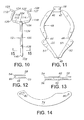
- FIG. 11 is a top plan view of the base part of the resection guide shown in FIGS. 1-8 ;
- FIG. 12 is an end view of one of the metal plates defining the bone-gripping members of the resection guide of FIGS. 1-8 ;
- FIG. 13 is a front elevation of the metal plate of FIG. 12 ;
- FIG. 14 is a top plan view of one of the top metal plates of the resection guide of FIGS. 1-8 ;
- FIG. 15 is an enlarged partial cross-section of the stylus of FIGS. 1-7 and 9 - 10 , taken along line 15 - 15 of FIG. 10 ;
- FIG. 16 is an enlarged partial cross-section taken along line 16 - 16 of FIG. 2 , showing the end of the stylus received in the connecting member of the resection guide;
- FIG. 17 is a perspective view of an assembly of an alternate embodiment of the stylus and resection guide of the present invention, illustrating examples of additional features that may be used with the stylus and resection guide;
- FIG. 18 is a top plan view of the assembly of FIG. 17 ;
- FIG. 19 is a bottom plan view of the assembly of FIGS. 17-18 ;
- FIG. 20 is a side elevation of the assembly of FIGS. 17-19 .
- anatomical references such as anterior, posterior, medial, lateral, superior, inferior, etcetera
- terms representing anatomical references may be used throughout the specification in reference to the orthopaedic implants and surgical instruments described herein as well as in reference to the patient's natural anatomy.
- Such terms have well-understood meanings in both the study of anatomy and the field of orthopaedics. Use of such anatomical reference terms in the written description and claims is intended to be consistent with their well-understood meanings unless noted otherwise.
- the stylus 12 is removably mounted to the resection guide, and is capable of movement with respect to the resection guide 10 as the resection guide 10 is expanded and contracted to mount the assembly to the patient's patella and to remove the assembly from the patient's patella once the desired resection is complete.
- the patella resection guide 10 and stylus 12 would be provided in the form of a kit, and assembly would be done intraoperatively, although the components 10 , 12 could be provided to the surgeon in a pre-assembled package.
- the illustrated patella resection guide 10 comprises a first curved arm 14 , a second curved arm 16 , a connecting member 18 , a curved ratchet 20 and a ratchet locking plate 22 .
- Each arm 14 , 16 has a first end 24 , 26 , a second end 28 , 30 spaced from the first end 24 , 26 , a first portion 32 , 34 extending from the first end 24 , 26 and a second portion 36 , 38 extending from the second end 28 , 30 toward the first portion 32 , 34 .
- the first end 24 of the first arm 14 is pivotably connected to the connecting member 18 about a first pivot axis 40 .
- the first end 26 of the second arm 16 is pivotably connected to the connecting member 18 about a second pivot axis 42 spaced from the first pivot axis 40 .
- the first portion 32 of the first arm 14 is pivotably connected to the second portion 36 of the first arm 14 about a third pivot axis 44 .
- the first portion 34 of the second arm 16 is pivotably connected to the second portion 38 of the second arm 16 about a fourth pivot axis 46 .
- the second end 28 of the first arm 14 is connected to the second end 30 of the second arm 16 about a fifth pivot axis 48 .
- the first pivot axis 40 , second pivot axis 42 , third pivot axis 44 , fourth pivot axis 46 and fifth pivot axis 48 are all parallel to each other, as shown in FIG. 3 , where the pivot axes 40 , 42 , 44 , 46 , 48 extend outward perpendicularly from the plane of the page.
- each of the pivot axes 40 , 42 , 44 , 46 , 48 are defined by hinged connections, and more particularly, by living hinges.
- “Living hinge” as used herein is intended to mean a thin flexible part of an element that joins two rigid parts together, allowing the rigid parts to bend along the line of the hinge.
- the patella resection guide 10 comprises an assembly of elements, including a base 49 (illustrated in FIG. 11 ) and additional components described below.
- the illustrated base 49 comprises a molded plastic component, and more particularly an injection molded component made as a single, unitary piece of a resin suitable for injection molding and for subsequent sterilization, such as polyethylene or polypropylene, for example. It is anticipated that a number of polymers will be usable to make the base 49 , such as polyamide polyphenylsulfone, polyethersulfone, polysulfone, polyketone, and polyarylamide. It will be recognized that any of numerous other plastic materials could be used to form the base 49 .
- the molding operation produces the base 49 with the thinner areas shown at 40 , 42 , 44 , 46 and 48 in FIG. 11 .
- the base 49 is flexible at these thinner areas so that the thinner areas effectively function as living hinges.
- the illustrated base 49 also includes two enlarged, concavely contoured paddles 51 , 53 adjacent to the fifth pivot axis 48 at the ends 24 , 26 of the arms 14 , 16 that are sized and shaped to function as grips: the surgeon may squeeze these paddles 51 , 53 to contract or close the resection guide 10 against the patella.
- the surfaces defining the paddles may have other shapes, such as a convex contour or a flat contour.
- the second portions 36 , 38 of the arms 14 , 16 include curved slots 55 , 57 (shown in phantom in FIG. 11 ) to receive portions of the curved ratchet 20 .
- One of the slots 55 and one end of the ratchet 20 have complementary end shapes so that one end of the ratchet 20 can be fixed to one arm 14 while the other end of the ratchet is free to move through the slot 57 in the other arm 16 .
- ratchet 20 and ratchet locking plate 22 represent one example of a releasable locking mechanism that may be used to lock the arms 14 , 16 in a particular configuration, such as the open configuration of FIGS. 1-3 , 8 and 17 - 19 and the closed configuration of FIG. 7 .
- Other locking mechanisms may be used: for example, clutch plates used in “quick clamps” may be used.
- Two of the additional components assembled with the base 49 to form the patella resection guide 10 are a set of bone-gripping members.
- the first portion 32 of the first arm 14 has a first bone-gripping member 50 extending toward the first portion 34 of the second arm 16 and the first portion 34 of the second arm 16 has a second bone-gripping member 52 extending toward the first portion 32 of the first arm 14 .
- the bone-gripping members 50 , 52 in the illustrated embodiment comprise a plurality of teeth with their points facing each other. A space is defined between the points of the teeth in which the patella is received and gripped by the teeth about its periphery, as described in more detail below.
- All of the teeth of the bone-gripping members 50 , 52 lie in a plane that is perpendicular to the pivot axes 40 , 42 , 44 , 46 , 48 of the resection guide 10 .
- the teeth are oriented so that when the patella is received between and engaged by the teeth, a plurality of points on the patella are engaged (such as three spaced points) so that the patella is held with no relative movement between the patella and the patella resection guide.
- the teeth of the bone-gripping members 50 , 52 are integral parts of planar plates or sheets that are parts of channel members.
- FIGS. 12-13 An example of such a channel member is shown at 54 in FIGS. 12-13 , where the plate or sheet that is shaped to define the bone-gripping teeth 50 is labeled 56 .
- the channel member 54 is C-shaped or U-shaped in end view and includes another planar plate or sheet 58 that overlies and is substantially parallel to the plate 56 .
- the two plates or sheets 56 , 58 are connected by a perpendicular plate 60 .
- a reduced-thickness portion of the base 49 is received in the space between the plates or sheets 56 , 58 , and the channel member is fixed to this portion of the base 49 through bolts, rivets or the like (shown in FIG. 3 at 62 and 64 ) extending through aligned holes formed in the plates or sheets 56 , 58 .
- the bone-gripping member 52 of the second arm 16 is essentially the mirror image of the structure described above for the first arm 14 , and the above description applies to the channel member of the second arm 16 as well; in FIGS. 3 and 5 - 6 , the channel member of the second arm 16 is labeled 66 , the parallel plates are labeled 68 , 70 and the perpendicular connecting plate is labeled 72 .
- the top surfaces of the plates 58 , 70 of the channel members 54 , 66 define co-planar first and second resection guide surfaces. The surgeon may rest a saw blade on these surfaces of these plates 58 , 70 to resect the posterior dome of the patella.
- Two additional plates are assembled with the base 49 to define the first and second arms 14 , 16 of the illustrated patella resection guide 10 .
- These additional top plates are labeled 74 and 76 in FIGS. 1-8 and are positioned above and parallel to the first and second resection guide surfaces defined by the top surfaces of the plates 58 , 70 of the channel members 54 , 66 .
- the upper plates 74 , 76 define parallel upper and lower planar surfaces that are parallel to and spaced the plane of the top surfaces of the plates 58 , 70 to define co-planar saw guide slots, sized and shaped so that a saw blade may pass through the guide slots.
- One of the guide slots is shown at 78 in FIGS. 4 and 5 .
- Both the upper and lower surfaces of the upper plates 74 , 76 define planar guide surfaces for the saw blade: instead of using the guide slot such as slot 78 , the surgeon may rest the saw blade against the top surface of one of the plates 74 , 76 to guide the saw blade during resection of the patella.
- the channel members 54 , 66 including the teeth of the opposed bone-gripping members 50 , 52 , and the upper plates 74 , 76 may be cut from a sheet of metal, by laser cutting, stamping, drilling, or otherwise cutting the sheet.
- the channel members 54 , 66 may then be formed from the cut sheets.
- the metal may comprise, for example, stainless steel or other metal suitable for orthopaedic instruments. It should be understood that other materials may be used as well, and the present invention is not limited to the use of stainless steel unless expressly called for in the claims. Generally, any material that has sufficient stiffness and that will not be damaged by the action of the saw blade acting against it is acceptable.
- FIG. 14 illustrates an example of one of the upper plates 74 of the first illustrated embodiment.
- the upper plate 74 includes a through hole 80 at one end and a slot 82 at its opposite end.
- the other plate 76 is the mirror image of the plate illustrated in FIG. 14 .
- the plates 74 , 76 are mounted to the base 49 through connections that allow both ends of the plates to pivot with respect to the base. Pins or the like may be used.
- the ends of the plates 74 , 76 that are adjacent to the slots 82 are received within slots in the connecting member 18 of the base 49 through bolts that extend through the slots 82 and nuts that allow these ends of the plates 74 , 76 to pivot and slide with respect to the base as the resection guide is expanded and contracted against the patella.
- the through holes 80 of the plates 74 , 76 are mounted on spindles or pins that extend upwardly from the base 49 .
- the plates 74 , 76 are sized and shaped so that the connections through the slots 82 are at the first ends 24 , 26 of the arms 14 , 16 and the connections through the through holes 80 are at the second portions 36 , 38 of the arms 14 , 16 .
- the plates 74 , 76 span the first, second, third and fourth hinges and pivot axes 40 , 42 , 44 , 46 .
- the relative positions of the plates 74 , 76 and the channel members e.g. 66 ) change as the resection guide is expanded and contracted, although the plates 74 , 76 and the sheets 58 , 70 remain parallel with a constant distance between the parallel surfaces as the resection guide is expanded and contracted.
- the connecting member 18 includes an upstanding portion 90 defining a through slot 92 (see FIG. 8 ) aligned along a central longitudinal plane through the resection guide 10 .
- the connecting member 18 includes a support surface 94 within the slot 92 that supports a portion of the stylus 12 .
- the stylus 12 includes an elongate member 100 having a free end 102 and a second end 104 .
- a cross-member 106 is integral with and extends from the elongate member 100 .
- the cross-member 106 has a first end 108 , a second end 110 , and a central portion 112 integral with the second end 104 of the elongate member 100 .
- a first end portion 114 is at the first end 108 and a second end portion 116 is at the second end 110 .
- the first end portion 114 is pivotably connected to the central portion 112 about a sixth pivot axis 118 and the second end portion 116 is pivotably connected to the central portion 112 about a seventh pivot axis 120 .
- the first end portion 114 of the stylus 12 includes a first mounting member 122 and the second end portion 116 of the stylus 12 includes a second mounting member 124 .
- the mounting members 122 , 124 in the illustrated embodiment comprise semi-cylindrical concave surfaces formed in thinner, more flexible portions of the stylus, and end tabs 125 , 127 extending outward for grasping.
- the mounting members 122 , 124 are sized and shaped to be snap fit about cylindrical portions 126 , 128 (see FIG. 8 ) of upstanding bosses 130 , 132 on the resection guide 10 .
- each of the pivot axes 118 , 120 are defined by hinged connections, and more particularly, by living hinges, similar to the living hinges described above for the resection guide 10 .
- the stylus 12 in the illustrated embodiment comprises a molded plastic component, and more particularly an injection molded component made as a single, unitary piece of a resin suitable for injection molding and for subsequent sterilization, such as polyethylene or polypropylene, for example, although other polymers such as polyamide polyphenylsulfone, polyethersulfone, polysulfone, polyketone, and polyarylamide are expected to be usable.
- the molding operation produces the stylus 12 with the thinner areas shown at 118 and 120 , along with the thinner more flexible mounting members 122 , 124 to allow the mounting members to be snap fit around the cylindrical portion 126 , 128 of the bosses 130 , 132 to removably mount the stylus 12 to the resection guide 10 .
- the living hinges at axes 118 , 120 allow the first and second end portions 114 , 116 to bend between the positions illustrated in FIG. 9 and FIG. 10 .
- the elongate member 100 of the stylus 12 has top and bottom surfaces that taper along a portion of their lengths to longitudinal edges 134 , 136 .
- the longitudinal edges 134 , 136 lie in planes that are parallel to and spaced at predetermined distances from the planes of the plates 58 , 70 , 74 , 76 and guide slot 78 .
- the elongate member 100 of the stylus 12 has a thinner portion 138 at the free end 102 extending toward the main body of the elongate member 100 .
- the central longitudinal axis 140 of the thinner portion 138 is vertically offset from the central longitudinal axis 142 of the main body of the elongate member 100 .
- the nearest edge 136 of the main body of the elongate member 100 lies in a plane that is spaced a first predetermined vertical distance d 1 from the plane of the resection guide surfaces defined by the plates 58 , 70 of the resection guide slot 78 .
- the stylus 12 can be flipped 180 degrees to the position shown in FIG. 4A . As shown in FIG.
- the nearest edge 134 of the main body of the elongate member 100 lies in a plane that is spaced a second predetermined vertical distance d 2 from the plane of the resection guide surfaces defined by the plates 58 , 70 of the resection guide slot 78 .
- the first and second predetermined vertical distances correspond with the depth of resection of the patella, and may be, for example, 11 mm and 8.5 mm, or some other desired distances.
- Indicia of the resection depth can be molded into or marked on the stylus if desired; for example, the stylus could be marked with a reference to 11 mm and a reference to 8.5 mm and with arrows pointing from the numbers to the appropriate edge. If the surgeon chooses to use the top surfaces of the plates 74 , 76 as the guide surfaces for the patella resection, additional patella resection levels are available to the surgeon.
- FIGS. 17-20 An alternative embodiment is illustrated in FIGS. 17-20 . This embodiment is similar to that shown in the first embodiment. Like parts have been labeled in the figures with like numbers, followed by the letter “A”. The above description of similarly labeled parts applies to the second embodiment as well as the first described embodiment.
- an integral flange 200 is provided adjacent to the ratchet locking plate 22 A to make it easier for the surgeon to unlock the ratchet 20 A when desired.
- opposing finger grips 202 , 204 are also provided on the outermost edges of the plates 74 , 76 . These finger grips 202 , 204 provide convenient contact areas for the surgeon to use when expanding and contracting the resection guide.
- the stylus 12 A of the embodiment of FIGS. 17-20 includes an additional cross-piece 206 extending out perpendicularly from both sides of the elongate member 100 A for added stability.
- the cross-piece 206 includes a transverse edge 137 intersecting and co-planar with the longitudinal edge 136 A.
- FIGS. 17-20 differs from the first illustrated embodiment is that in the embodiment of FIGS. 17-20 , the bosses are not discreet components assembled with the base 49 and plates 74 , 76 , like the bosses 130 , 132 . Instead, integral portions 208 , 209 of the second portion 36 A, 38 A of each arm have slots (shown at 210 in FIG. 20 ) that receive the ends of the top plates 74 A, 76 A and define cylindrical bosses like those shown at 126 and 128 to which the stylus 12 A may be mounted.
- a spindle or post (not shown) extends through the bosses of the integral portions 208 , 209 for rotatably or pivotably mounting the plates 74 A, 76 A to the second portions 36 A, 38 A of the base 49 A.
- the paddles 51 A, 53 A are shaped to have a lower profile in the embodiment of FIGS. 17-20 .
- FIGS. 17-20 Another feature of the embodiment of FIGS. 17-20 that differs from the first illustrated embodiment is that in the embodiment of FIGS. 17-20 , the ratchet 20 A is injection molded as an integral part of the second portion 36 A of the first arm 14 A rather than as a separate element assembled with the molded base 49 as in the first illustrated embodiment.
- the surgeon would make a standard incision and then partially or fully evert the patient's patella to expose the posterior side of the patella. If not pre-assembled, the surgeon would determine the preferred level of resection (for example, 8.5 mm or 11 mm) and the surgeon or operating room staff would then flip the stylus 12 , 12 A to the appropriate orientation (that is with either edge 144 or edge 146 facing down) for the preferred level of resection, then assemble the resection guide 10 , 10 A and the stylus 12 , 12 A by inserting the end 102 , 102 A of the stylus 12 , 12 A in the slot 92 of the upstanding member 90 and snapping the mounting members 122 , 124 , 122 A, 124 A onto the cylindrical portions 126 , 128 of the bosses 130 , 132 or bosses 208 , 209 of the resection guide 10 A.
- the preferred level of resection for example, 8.5 mm or 11 mm
- the surgeon or operating room staff would then flip
- the surgeon places the assembly such that the arms 14 , 14 A, 16 , 16 A are near opposed peripheral edges (either medial and lateral edges or superior and inferior edges) of the patella.
- the lower longitudinal edge 134 (or 136 , 136 A if the stylus is oriented with this edge facing downward toward the plates 74 , 74 A, 76 , 76 A) is placed against a surface of the patella, such as the most posterior surface of the patella. If the stylus has a cross-piece such as cross-piece 206 in the embodiment of FIGS.
- the additional transverse edge 137 provides additional stability for placement of the stylus on the posterior patella surface.
- the saw guide slots 78 , 78 A are positioned at a known, fixed distance from the desired surface of the patella to set the resection level with reference to this patella surface.
- the surgeon may then close or contract the patella resection guide 10 , 10 A about the patella until the gripping members or teeth 50 , 50 A, 52 , 52 A contact and grip the periphery of the patella.
- the surgeon may close or contract the patella resection guide 10 by squeezing the paddles 51 , 53 .
- the surgeon may close or contract the patella resection guide 10 , 10 A about the patella by squeezing the finger grips 202 , 204 or the paddles 51 A, 53 A.
- the arms 14 , 14 A, 16 , 16 A pivot on their axes 40 , 40 A, 42 , 42 A, 44 , 44 A, 46 , 46 A, 48 , 48 A and the plates 74 , 74 A, 76 , 76 A pivot and slide with respect to the base 49 , 49 A.
- the stylus 12 , 12 A pivots about the cylindrical portions (elements 126 , 128 in the first embodiment) of the bosses 130 , 132 of the resection guide 10 (or bosses of the integral portions 208 , 209 of the resection guide 10 A) and about the pivot axes 118 , 118 A, 120 , 120 A, and the thinner portion 138 , 138 A of the stylus translates on the surface 94 in the slot 92 .
- the second portions 36 , 36 A, 38 , 38 A of the arms 14 , 14 A 16 , 16 A move closer together and the ratchet 20 , 20 A moves with respect to the second portion 38 , 38 A of arms 16 , 16 A.
- the ratchet 20 , 20 A moves, its teeth are engaged by the locking plate 22 , 22 A.
- the gripping members 50 , 50 A, 52 , 52 A squeeze the patella periphery between them, the patella is firmly gripped and the locking plate 22 , 22 A locks the ratchet 20 , 20 A and the arms 14 , 14 A, 16 , 16 A in this position.
- the resection guide 10 , 10 A is fixed in a desired position with respect to the patient's patella, with the resection guide slots 78 , 78 A positioned so that the pre-determined desired level of resection is set.
- the surgeon may then place a saw blade through one of the guide slots 78 , 78 A or on the surface of one of the plates 74 , 74 A, 76 , 76 A and perform the resection.
- the surgeon may disengage the locking plate 22 , 22 A from the ratchet 20 , 20 A, expand the resection guide and remove the resection guide.
- the surgeon may optionally remove the stylus 12 , 12 A from the resection guide 10 , 10 A before performing the resection.
- the surgeon may easily press on the tabs 125 , 125 A, 127 , 127 A to release the mounting members 122 , 122 A, 124 , 124 A and slide the end 102 , 102 A of the stylus 12 , 12 A out of the slot 92 , 92 A.
- FIGS. 1 and 7 it will be appreciated by comparing FIGS. 1 and 7 that the distance between the bone-gripping members 50 , 50 A, 52 , 52 A varies substantially between the fully open or expanded position of FIG. 1 and the fully closed or contracted position of FIG. 7 .
- the resection guide can be locked in substantially any position between those shown in FIGS. 1 and 7 .
- a single resection guide 10 , 10 A and stylus 12 , 12 A can be used to resect patellae of a large variety of sizes.
- resection guide and stylus may be varied from those described above.
- the illustrated embodiments use living hinges to define the pivot axes 40 , 40 A, 42 , 42 A, 44 , 44 A, 46 , 46 A, 48 , 48 A, 118 , 118 A, 120 , 120 A; such hinges allow for parts of the resection guide and stylus to be injection molded.
- Such living hinges are well-suited for resection guides and styluses that are intended for a limited number of uses, and are particularly well-suited for guides and styluses that are intended for a single use. For guides and styluses intended to multiple uses, more robust mechanical hinges may be more appropriate.
- the patella resection guide 10 , 10 A of the present invention may be clamped onto patellae of various sizes, with the stylus 12 , 12 A in place. Regardless of the size of the patella, an accurate resection may be performed. In addition, substantial parts of the assembly may be made relatively inexpensively (by injection molding of polymers, for example). The patella resection guide 10 , 10 A and stylus 12 , 12 A are thus suitable for economical use as single use instruments.
Landscapes
- Health & Medical Sciences (AREA)
- Surgery (AREA)
- Life Sciences & Earth Sciences (AREA)
- Biomedical Technology (AREA)
- Medical Informatics (AREA)
- Oral & Maxillofacial Surgery (AREA)
- Nuclear Medicine, Radiotherapy & Molecular Imaging (AREA)
- Transplantation (AREA)
- Physical Education & Sports Medicine (AREA)
- Engineering & Computer Science (AREA)
- Orthopedic Medicine & Surgery (AREA)
- Heart & Thoracic Surgery (AREA)
- Dentistry (AREA)
- Molecular Biology (AREA)
- Animal Behavior & Ethology (AREA)
- General Health & Medical Sciences (AREA)
- Public Health (AREA)
- Veterinary Medicine (AREA)
- Surgical Instruments (AREA)
- Prostheses (AREA)
Priority Applications (8)
| Application Number | Priority Date | Filing Date | Title |
|---|---|---|---|
| US13/176,802 US8821501B2 (en) | 2010-09-24 | 2011-07-06 | Patella resectioning guide and assembly |
| EP12191753.8A EP2556801B1 (fr) | 2010-09-24 | 2011-07-28 | Assemblage de résection de rotule |
| EP11175824.9A EP2433574B1 (fr) | 2010-09-24 | 2011-07-28 | Guide de résection de rotule et assemblage |
| ES11175824.9T ES2439715T3 (es) | 2010-09-24 | 2011-07-28 | Guía y conjunto de resección de rótula |
| DK11175824.9T DK2433574T3 (da) | 2010-09-24 | 2011-07-28 | Patellaresektionsføring og -arrangement |
| AU2011213859A AU2011213859B2 (en) | 2010-09-24 | 2011-08-24 | Patella resectioning guide and assembly |
| JP2011206891A JP5868644B2 (ja) | 2010-09-24 | 2011-09-22 | 膝蓋切除ガイド及び組立体 |
| CN201110297286.0A CN102551843B (zh) | 2010-09-24 | 2011-09-23 | 髌骨切除导向器和髌骨切除组件 |
Applications Claiming Priority (2)
| Application Number | Priority Date | Filing Date | Title |
|---|---|---|---|
| US38609710P | 2010-09-24 | 2010-09-24 | |
| US13/176,802 US8821501B2 (en) | 2010-09-24 | 2011-07-06 | Patella resectioning guide and assembly |
Publications (2)
| Publication Number | Publication Date |
|---|---|
| US20120078261A1 US20120078261A1 (en) | 2012-03-29 |
| US8821501B2 true US8821501B2 (en) | 2014-09-02 |
Family
ID=44993461
Family Applications (1)
| Application Number | Title | Priority Date | Filing Date |
|---|---|---|---|
| US13/176,802 Expired - Fee Related US8821501B2 (en) | 2010-09-24 | 2011-07-06 | Patella resectioning guide and assembly |
Country Status (7)
| Country | Link |
|---|---|
| US (1) | US8821501B2 (fr) |
| EP (2) | EP2433574B1 (fr) |
| JP (1) | JP5868644B2 (fr) |
| CN (1) | CN102551843B (fr) |
| AU (1) | AU2011213859B2 (fr) |
| DK (1) | DK2433574T3 (fr) |
| ES (1) | ES2439715T3 (fr) |
Cited By (4)
| Publication number | Priority date | Publication date | Assignee | Title |
|---|---|---|---|---|
| US20180353220A1 (en) * | 2017-06-07 | 2018-12-13 | Warsaw Orthopedic, Inc | Spinal implant system and method |
| US11246719B2 (en) * | 2013-08-13 | 2022-02-15 | Brainlab Ag | Medical registration apparatus and method for registering an axis |
| US20220409217A1 (en) * | 2021-06-24 | 2022-12-29 | Azurmeds Inc. | Surgical instruments and methods of use |
| US11723677B2 (en) | 2020-10-16 | 2023-08-15 | Howmedica Osteonics Corp. | Patella resection guide with independent adjustment |
Families Citing this family (21)
| Publication number | Priority date | Publication date | Assignee | Title |
|---|---|---|---|---|
| US8821501B2 (en) | 2010-09-24 | 2014-09-02 | Depuy (Ireland) | Patella resectioning guide and assembly |
| US8747410B2 (en) * | 2010-10-26 | 2014-06-10 | Zimmer, Inc. | Patellar resection instrument with variable depth guide |
| US8968321B2 (en) | 2011-06-30 | 2015-03-03 | Depuy (Ireland) | Patella resection guide with locating features and method of using the same |
| EP2725992B1 (fr) | 2011-06-30 | 2016-03-23 | Depuy (Ireland) | Pince à rotule et instrument chirurgical avec guide de forage |
| US8986306B2 (en) | 2011-06-30 | 2015-03-24 | Depuy (Ireland) | Patella orthopaedic surgical method |
| USD679395S1 (en) | 2011-06-30 | 2013-04-02 | Depuy (Ireland) | Combination patella clamp and drill guide |
| USD666720S1 (en) * | 2011-06-30 | 2012-09-04 | Depuy Products, Inc. | Patella resection guide |
| US8979854B2 (en) | 2011-06-30 | 2015-03-17 | Depuy (Ireland) | Patella orthopaedic surgical instrument assembly |
| US8915923B2 (en) | 2011-09-28 | 2014-12-23 | Depuy (Ireland) | Patella resection assembly |
| US8998912B2 (en) | 2011-09-28 | 2015-04-07 | Depuy (Ireland) | Clamping patella drill guide |
| US9078676B2 (en) | 2011-09-28 | 2015-07-14 | Depuy (Ireland) | Patella drilling system |
| US9078772B2 (en) | 2011-09-28 | 2015-07-14 | Depuy (Ireland) | Rotatable patella drill guide |
| US8998913B2 (en) | 2011-09-28 | 2015-04-07 | Depuy (Ireland) | Patella resection assembly |
| US10085758B2 (en) | 2012-09-28 | 2018-10-02 | Depuy Ireland Unlimited Company | Patella drill guide and trial surgical instrument having an alignment bore formed therein and method of using the same |
| US9855065B2 (en) | 2012-09-28 | 2018-01-02 | Depuy Ireland Unlimited Company | Orthopaedic surgical instrument assembly for implanting a prosthetic patella component |
| US10335163B2 (en) | 2013-03-05 | 2019-07-02 | Depuy Ireland Unlimited Company | Polymer 4-in-2 femoral cutting instrument having separable A/P and chamfer cutting blocks |
| EP3072462B1 (fr) | 2015-03-27 | 2017-10-04 | DePuy Ireland Unlimited Company | Instrument chirurgical orthopédique |
| CN110022782A (zh) * | 2016-10-26 | 2019-07-16 | 保罗·C·麦卡菲 | 用于脊柱手术的牵张工具 |
| CN106691545B (zh) * | 2017-01-24 | 2023-11-10 | 丽水市人民医院 | 一种髌下脂肪垫切除工具及其使用方法 |
| US12076025B2 (en) | 2022-05-11 | 2024-09-03 | DePuy Synthes Products, Inc. | Polymer cutting block |
| EP4534024A1 (fr) * | 2023-10-05 | 2025-04-09 | Aesculap AG | Dispositif de serrage de rotule |
Citations (96)
| Publication number | Priority date | Publication date | Assignee | Title |
|---|---|---|---|---|
| US2008011A (en) | 1929-04-19 | 1935-07-16 | William H Foster | Lathe |
| US3835849A (en) | 1973-01-26 | 1974-09-17 | Guire G Mc | Bone clamp and adjustable drill guide |
| US4194861A (en) | 1976-05-04 | 1980-03-25 | Keller Research & Development, Inc. | Compact dowel hole spacing and drilling device |
| USD260927S (en) | 1979-03-14 | 1981-09-22 | Glenn Edward C | Dowell pin positioner |
| USD281622S (en) | 1983-08-29 | 1985-12-03 | Diamond Michael K | Combined dental mirror and moisture control apparatus |
| US4565192A (en) | 1984-04-12 | 1986-01-21 | Shapiro James A | Device for cutting a patella and method therefor |
| US4633862A (en) | 1985-05-30 | 1987-01-06 | Petersen Thomas D | Patellar resection sawguide |
| US5002547A (en) | 1987-02-07 | 1991-03-26 | Pfizer Hospital Products Group, Inc. | Apparatus for knee prosthesis |
| US5021055A (en) | 1990-09-19 | 1991-06-04 | Intermedics Orthopedics, Inc. | Patellar clamp and surgical saw guide |
| US5108401A (en) | 1991-04-12 | 1992-04-28 | New York Society For The Relief Of The Ruptured And Crippled, Maintaining The Hospital For Special Surgery | Patella cutting clamp |
| US5116338A (en) | 1988-02-03 | 1992-05-26 | Pfizer Hospital Products Group, Inc. | Apparatus for knee prosthesis |
| US5129908A (en) | 1990-01-23 | 1992-07-14 | Petersen Thomas D | Method and instruments for resection of the patella |
| US5129907A (en) | 1990-12-10 | 1992-07-14 | Zimmer, Inc. | Patellar clamp and reamer with adjustable stop |
| US5147365A (en) | 1991-08-19 | 1992-09-15 | Intermedics Orthopedics, Inc. | Patellar osteotomy guide |
| US5174693A (en) | 1990-09-28 | 1992-12-29 | Lee Valley Tools Ltd. | Drilling jig |
| US5222955A (en) | 1991-02-08 | 1993-06-29 | Mikhail Michael W E | Method for implanting a patellar prosthesis |
| US5250050A (en) | 1987-02-07 | 1993-10-05 | Pfizer Hospital Products Group, Inc. | Apparatus for knee prosthesis |
| US5284482A (en) | 1991-02-08 | 1994-02-08 | Mikhail Michael W E | Universal patellar clamp |
| US5284485A (en) | 1992-09-16 | 1994-02-08 | Ethicon, Inc. | Endoscopic knotting device |
| US5312409A (en) | 1992-06-01 | 1994-05-17 | Mclaughlin Robert E | Drill alignment guide |
| US5382254A (en) | 1989-07-18 | 1995-01-17 | United States Surgical Corporation | Actuating handle for surgical instruments |
| US5415663A (en) | 1993-12-02 | 1995-05-16 | Johnson & Johnson Orthopaedics, Inc. | Orthopaedic cutting guides with retractable saw blade slots |
| US5470328A (en) | 1994-07-21 | 1995-11-28 | Snowden-Pencer, Inc. | Surgical instrument handle and actuator means |
| US5484451A (en) | 1992-05-08 | 1996-01-16 | Ethicon, Inc. | Endoscopic surgical instrument and staples for applying purse string sutures |
| USD367531S (en) | 1994-06-27 | 1996-02-27 | Zimmer, Inc. | External fixation clamp |
| US5520692A (en) | 1995-02-28 | 1996-05-28 | Wright Medical Technology, Inc. | Adjustable depth patella recessing guide and method |
| US5536271A (en) | 1994-06-02 | 1996-07-16 | Depuy, Inc. | Patella reaming system |
| US5542947A (en) | 1995-05-12 | 1996-08-06 | Huwmedica Inc. | Slotted patella resection guide and stylus |
| USD373635S (en) | 1995-11-14 | 1996-09-10 | Zimmer, Inc. | External fixation clamp |
| US5575793A (en) | 1995-02-15 | 1996-11-19 | Smith & Nephew Richards Inc. | Patella clamp apparatus |
| US5582615A (en) | 1995-10-30 | 1996-12-10 | Pilling Weck, Incorporated | Handle for surgical clip applicator systems |
| US5593450A (en) | 1995-02-27 | 1997-01-14 | Johnson & Johnson Professional, Inc. | Oval domed shaped patella prosthesis |
| FR2737848A1 (fr) | 1995-08-16 | 1997-02-21 | Lanternier Hubert | Instrumentation de mise en place d'un implant rotulien prothetique |
| US5611802A (en) | 1995-02-14 | 1997-03-18 | Samuelson; Kent M. | Method and apparatus for resecting bone |
| US5626607A (en) | 1995-04-03 | 1997-05-06 | Heartport, Inc. | Clamp assembly and method of use |
| US5667512A (en) | 1996-05-03 | 1997-09-16 | Metagen, Llc | Patellar resection guide |
| US5827279A (en) | 1996-12-06 | 1998-10-27 | Ethicon Endo-Surgery, Inc. | Knife coupler mechanism for an endoscopic instrument |
| US5941884A (en) | 1998-10-09 | 1999-08-24 | Osteonics Corp. | Patella preparation apparatus and method |
| US5944723A (en) | 1998-03-27 | 1999-08-31 | Johnson & Johnson Professional, Inc. | Locking orthopaedic clamping tool |
| WO1999045856A1 (fr) | 1998-03-13 | 1999-09-16 | Macey Theodore I | Procede et dispositif de serrage |
| US5968051A (en) | 1995-07-27 | 1999-10-19 | Johnson & Johnson Professional, Inc. | Patella clamping device |
| US6010509A (en) | 1998-07-01 | 2000-01-04 | The Dana Center For Orthopaedic Implants | Patella resection drill and prosthesis implantation device |
| EP0992222A2 (fr) | 1998-09-28 | 2000-04-12 | JOHNSON & JOHNSON PROFESSIONAL Inc. | Outil orthopédique de serrage modulaire |
| US6056754A (en) | 1994-09-02 | 2000-05-02 | Hudson Surgical Design, Inc. | Method and apparatus for patella resection and guide handle |
| US6074425A (en) | 1994-01-14 | 2000-06-13 | Biomedical Engineering Trust I | Fixed bearing joint endoprosthesis |
| US6190391B1 (en) | 1999-10-01 | 2001-02-20 | Bristol-Myers Squibb Company | Method of preparing a resected posterior surface of a patella to receive a prosthetic element |
| US6205884B1 (en) | 1998-02-27 | 2001-03-27 | Depuy Orthopaedics, Inc. | Handle assembly |
| USD459474S1 (en) | 2001-06-19 | 2002-06-25 | Impra, Inc. | Stent delivery apparatus |
| US6419675B1 (en) | 1999-09-03 | 2002-07-16 | Conmed Corporation | Electrosurgical coagulating and cutting instrument |
| US20020115987A1 (en) | 2001-02-16 | 2002-08-22 | Path | Needle cannula removal by extraction |
| USD463550S1 (en) | 2001-03-27 | 2002-09-24 | Thomas Sherman | Eyedropper positioning device |
| US20030163137A1 (en) | 2002-02-26 | 2003-08-28 | Smucker Donald M. | Patella resection guide |
| US20040153066A1 (en) | 2003-02-03 | 2004-08-05 | Coon Thomas M. | Apparatus for knee surgery and method of use |
| US6855150B1 (en) | 2001-07-13 | 2005-02-15 | Timothy R. Linehan | Patellar trial and drill guide for use in knee replacement surgery |
| US6866667B2 (en) | 2002-09-03 | 2005-03-15 | Symmetry Medical, Inc. | Patellar milling clamp |
| US20050240196A1 (en) | 2004-03-09 | 2005-10-27 | Davis Kenneth P | Apparatus for use in orthopaedic surgery |
| WO2005110249A1 (fr) | 2004-05-17 | 2005-11-24 | Imp Limited | Dispositif de chirurgie orthopedique |
| US20060142777A1 (en) * | 2004-12-27 | 2006-06-29 | Howmedica Osteonics Corp. | Patella resection clamp |
| US20070118141A1 (en) | 2003-02-13 | 2007-05-24 | Howmedica Osteonics Corp. | Modular patella instrument |
| GB2433698A (en) | 2005-12-28 | 2007-07-04 | Derek James Wallace Mcminn | Patellar Button and knee prothesis for resisting medial and lateral forces |
| US20070162031A1 (en) | 2005-05-18 | 2007-07-12 | Alex Hogg | Patellar resection tool |
| US20070179626A1 (en) | 2005-11-30 | 2007-08-02 | De La Barrera Jose L M | Functional joint arthroplasty method |
| USD549331S1 (en) | 2006-09-13 | 2007-08-21 | Senko Medical Instrument Mfg., Co. | Patella trap retractor for knee arthroplasty |
| US20070233142A1 (en) | 2006-03-14 | 2007-10-04 | Oliver Ralph S | Apparatus and method for implementing patella resection guide during minimally invasive surgery |
| US20070260227A1 (en) | 2005-07-11 | 2007-11-08 | Phan Christopher U | Axial load limiting system and methods |
| US7356902B2 (en) | 2003-11-13 | 2008-04-15 | Black & Decker Inc. | Lock set installation apparatus and kit and method of using the same |
| US20080097450A1 (en) | 2006-09-14 | 2008-04-24 | Zimmer Technology, Inc. | Patella clamp |
| US20080177394A1 (en) | 2006-10-18 | 2008-07-24 | Howmedica Osteonics Corp. | Mis patellar preparation |
| EP1967143A2 (fr) | 2007-03-08 | 2008-09-10 | DePuy Products, Inc. | Instrument orthopédique avec éléments de revêtement de charge |
| US20080228190A1 (en) | 2007-03-02 | 2008-09-18 | Eugene Sherry | In situ patellar fixing system |
| WO2008112996A1 (fr) | 2007-03-14 | 2008-09-18 | Conformis, Inc. | Outil chirurgical pour arthroplastie |
| US7566335B1 (en) | 2004-11-22 | 2009-07-28 | Biomet Manufacturing Corp. | Method and apparatus for patella resection |
| US20090264737A1 (en) | 2006-04-07 | 2009-10-22 | Joerg Haechler | Patella tracking |
| US20090326661A1 (en) | 2008-06-30 | 2009-12-31 | Wright Abraham P | Implantable patella component having a thickened superior edge |
| US20100030223A1 (en) | 2006-10-12 | 2010-02-04 | Waldemar Link Gmbh & Co., Kg | Modular patella instrument |
| US20100152742A1 (en) | 2003-05-12 | 2010-06-17 | Corin Limited | Head centering jig for femoral resurfacing |
| US20100168753A1 (en) | 2008-12-29 | 2010-07-01 | Edwards Jon M | Orthopaedic cutting block having a chemically etched metal insert and method of manufacturing |
| US20100204701A1 (en) | 2000-05-01 | 2010-08-12 | Arthrosurface Incorporated | System and Method for Joint Resurface Repair |
| US7780594B2 (en) | 2005-10-07 | 2010-08-24 | Alphatec Spine, Inc. | Retractor and methods of use |
| US7891071B2 (en) | 2004-10-22 | 2011-02-22 | Howmedica Osteonics Corp. | Universal coupler |
| USD634011S1 (en) | 2010-07-29 | 2011-03-08 | Michael Phillips | Surgical clip |
| US20110066193A1 (en) | 2001-05-25 | 2011-03-17 | Conformis, Inc. | Surgical Tools for Arthroplasty |
| USD638541S1 (en) | 2010-05-28 | 2011-05-24 | Zimmer, Inc. | Femoral prosthesis insertion tool |
| US7972383B2 (en) | 2008-06-30 | 2011-07-05 | Depuy Products, Inc. | Implantable patella component having a thickened superior edge |
| USD642678S1 (en) | 2010-06-01 | 2011-08-02 | Zimmer, Inc. | Pin pulling tool |
| USD646389S1 (en) | 2010-06-01 | 2011-10-04 | Zimmer, Inc. | Patella osteotomy guide |
| US20120078261A1 (en) | 2010-09-24 | 2012-03-29 | Depuy Products, Inc. | Patella resectioning guide and assembly |
| US20130023883A1 (en) | 2011-06-30 | 2013-01-24 | Wright Abraham P | Patella orthopaedic surgical instrument assembly |
| US20130023890A1 (en) | 2011-06-30 | 2013-01-24 | Maja Kecman | Patella clamp and drill guide surgical instrument |
| US20130030443A1 (en) | 2011-06-30 | 2013-01-31 | Wright Abraham P | Patella drill guide and clamp assembly |
| US20130030539A1 (en) | 2011-06-30 | 2013-01-31 | Wright Abraham P | Patella orthopaedic surgical method |
| US20130035693A1 (en) | 2011-06-30 | 2013-02-07 | Wright Abraham P | Patella resection guide with locating features and method of using the same |
| US20130079789A1 (en) | 2011-09-28 | 2013-03-28 | Raymond E. Randle | Patella drilling system |
| US20130079788A1 (en) | 2011-09-28 | 2013-03-28 | Richard Spencer Jones | Clamping patella drill guide |
| US20130079787A1 (en) | 2011-09-28 | 2013-03-28 | Richard Spencer Jones | Rotatable patella drill guide |
| US20130211410A1 (en) | 2012-02-07 | 2013-08-15 | Conformis, Inc. | Patella Resection Instrument Guide Having Optional Patient-Specific Features |
-
2011
- 2011-07-06 US US13/176,802 patent/US8821501B2/en not_active Expired - Fee Related
- 2011-07-28 EP EP11175824.9A patent/EP2433574B1/fr not_active Not-in-force
- 2011-07-28 ES ES11175824.9T patent/ES2439715T3/es active Active
- 2011-07-28 EP EP12191753.8A patent/EP2556801B1/fr not_active Not-in-force
- 2011-07-28 DK DK11175824.9T patent/DK2433574T3/da active
- 2011-08-24 AU AU2011213859A patent/AU2011213859B2/en not_active Ceased
- 2011-09-22 JP JP2011206891A patent/JP5868644B2/ja not_active Expired - Fee Related
- 2011-09-23 CN CN201110297286.0A patent/CN102551843B/zh not_active Expired - Fee Related
Patent Citations (105)
| Publication number | Priority date | Publication date | Assignee | Title |
|---|---|---|---|---|
| US2008011A (en) | 1929-04-19 | 1935-07-16 | William H Foster | Lathe |
| US3835849A (en) | 1973-01-26 | 1974-09-17 | Guire G Mc | Bone clamp and adjustable drill guide |
| US4194861A (en) | 1976-05-04 | 1980-03-25 | Keller Research & Development, Inc. | Compact dowel hole spacing and drilling device |
| USD260927S (en) | 1979-03-14 | 1981-09-22 | Glenn Edward C | Dowell pin positioner |
| USD281622S (en) | 1983-08-29 | 1985-12-03 | Diamond Michael K | Combined dental mirror and moisture control apparatus |
| US4565192A (en) | 1984-04-12 | 1986-01-21 | Shapiro James A | Device for cutting a patella and method therefor |
| US4633862A (en) | 1985-05-30 | 1987-01-06 | Petersen Thomas D | Patellar resection sawguide |
| US5002547A (en) | 1987-02-07 | 1991-03-26 | Pfizer Hospital Products Group, Inc. | Apparatus for knee prosthesis |
| US5250050A (en) | 1987-02-07 | 1993-10-05 | Pfizer Hospital Products Group, Inc. | Apparatus for knee prosthesis |
| US5116338A (en) | 1988-02-03 | 1992-05-26 | Pfizer Hospital Products Group, Inc. | Apparatus for knee prosthesis |
| US5382254A (en) | 1989-07-18 | 1995-01-17 | United States Surgical Corporation | Actuating handle for surgical instruments |
| US5129908A (en) | 1990-01-23 | 1992-07-14 | Petersen Thomas D | Method and instruments for resection of the patella |
| US5021055A (en) | 1990-09-19 | 1991-06-04 | Intermedics Orthopedics, Inc. | Patellar clamp and surgical saw guide |
| US5174693A (en) | 1990-09-28 | 1992-12-29 | Lee Valley Tools Ltd. | Drilling jig |
| US5129907A (en) | 1990-12-10 | 1992-07-14 | Zimmer, Inc. | Patellar clamp and reamer with adjustable stop |
| US5222955A (en) | 1991-02-08 | 1993-06-29 | Mikhail Michael W E | Method for implanting a patellar prosthesis |
| US5284482A (en) | 1991-02-08 | 1994-02-08 | Mikhail Michael W E | Universal patellar clamp |
| US5108401A (en) | 1991-04-12 | 1992-04-28 | New York Society For The Relief Of The Ruptured And Crippled, Maintaining The Hospital For Special Surgery | Patella cutting clamp |
| US5147365A (en) | 1991-08-19 | 1992-09-15 | Intermedics Orthopedics, Inc. | Patellar osteotomy guide |
| US5484451A (en) | 1992-05-08 | 1996-01-16 | Ethicon, Inc. | Endoscopic surgical instrument and staples for applying purse string sutures |
| US5312409A (en) | 1992-06-01 | 1994-05-17 | Mclaughlin Robert E | Drill alignment guide |
| US5284485A (en) | 1992-09-16 | 1994-02-08 | Ethicon, Inc. | Endoscopic knotting device |
| US5415663A (en) | 1993-12-02 | 1995-05-16 | Johnson & Johnson Orthopaedics, Inc. | Orthopaedic cutting guides with retractable saw blade slots |
| US6074425A (en) | 1994-01-14 | 2000-06-13 | Biomedical Engineering Trust I | Fixed bearing joint endoprosthesis |
| US5536271A (en) | 1994-06-02 | 1996-07-16 | Depuy, Inc. | Patella reaming system |
| USD367531S (en) | 1994-06-27 | 1996-02-27 | Zimmer, Inc. | External fixation clamp |
| US5470328A (en) | 1994-07-21 | 1995-11-28 | Snowden-Pencer, Inc. | Surgical instrument handle and actuator means |
| US6056754A (en) | 1994-09-02 | 2000-05-02 | Hudson Surgical Design, Inc. | Method and apparatus for patella resection and guide handle |
| US5611802A (en) | 1995-02-14 | 1997-03-18 | Samuelson; Kent M. | Method and apparatus for resecting bone |
| US5575793A (en) | 1995-02-15 | 1996-11-19 | Smith & Nephew Richards Inc. | Patella clamp apparatus |
| US5593450A (en) | 1995-02-27 | 1997-01-14 | Johnson & Johnson Professional, Inc. | Oval domed shaped patella prosthesis |
| US5520692A (en) | 1995-02-28 | 1996-05-28 | Wright Medical Technology, Inc. | Adjustable depth patella recessing guide and method |
| US5626607A (en) | 1995-04-03 | 1997-05-06 | Heartport, Inc. | Clamp assembly and method of use |
| US5542947A (en) | 1995-05-12 | 1996-08-06 | Huwmedica Inc. | Slotted patella resection guide and stylus |
| US5968051A (en) | 1995-07-27 | 1999-10-19 | Johnson & Johnson Professional, Inc. | Patella clamping device |
| FR2737848A1 (fr) | 1995-08-16 | 1997-02-21 | Lanternier Hubert | Instrumentation de mise en place d'un implant rotulien prothetique |
| US5582615A (en) | 1995-10-30 | 1996-12-10 | Pilling Weck, Incorporated | Handle for surgical clip applicator systems |
| USD373635S (en) | 1995-11-14 | 1996-09-10 | Zimmer, Inc. | External fixation clamp |
| US5667512A (en) | 1996-05-03 | 1997-09-16 | Metagen, Llc | Patellar resection guide |
| US5827279A (en) | 1996-12-06 | 1998-10-27 | Ethicon Endo-Surgery, Inc. | Knife coupler mechanism for an endoscopic instrument |
| US6205884B1 (en) | 1998-02-27 | 2001-03-27 | Depuy Orthopaedics, Inc. | Handle assembly |
| WO1999045856A1 (fr) | 1998-03-13 | 1999-09-16 | Macey Theodore I | Procede et dispositif de serrage |
| US5944723A (en) | 1998-03-27 | 1999-08-31 | Johnson & Johnson Professional, Inc. | Locking orthopaedic clamping tool |
| US6010509A (en) | 1998-07-01 | 2000-01-04 | The Dana Center For Orthopaedic Implants | Patella resection drill and prosthesis implantation device |
| EP0992222A2 (fr) | 1998-09-28 | 2000-04-12 | JOHNSON & JOHNSON PROFESSIONAL Inc. | Outil orthopédique de serrage modulaire |
| US5941884A (en) | 1998-10-09 | 1999-08-24 | Osteonics Corp. | Patella preparation apparatus and method |
| US6419675B1 (en) | 1999-09-03 | 2002-07-16 | Conmed Corporation | Electrosurgical coagulating and cutting instrument |
| US6190391B1 (en) | 1999-10-01 | 2001-02-20 | Bristol-Myers Squibb Company | Method of preparing a resected posterior surface of a patella to receive a prosthetic element |
| US20100204701A1 (en) | 2000-05-01 | 2010-08-12 | Arthrosurface Incorporated | System and Method for Joint Resurface Repair |
| US20020115987A1 (en) | 2001-02-16 | 2002-08-22 | Path | Needle cannula removal by extraction |
| USD463550S1 (en) | 2001-03-27 | 2002-09-24 | Thomas Sherman | Eyedropper positioning device |
| US20110066193A1 (en) | 2001-05-25 | 2011-03-17 | Conformis, Inc. | Surgical Tools for Arthroplasty |
| USD459474S1 (en) | 2001-06-19 | 2002-06-25 | Impra, Inc. | Stent delivery apparatus |
| US6855150B1 (en) | 2001-07-13 | 2005-02-15 | Timothy R. Linehan | Patellar trial and drill guide for use in knee replacement surgery |
| US20030163137A1 (en) | 2002-02-26 | 2003-08-28 | Smucker Donald M. | Patella resection guide |
| US20080114366A1 (en) | 2002-02-26 | 2008-05-15 | Zimmer, Inc. | Patella resection guide |
| US7344540B2 (en) | 2002-02-26 | 2008-03-18 | Zimmer, Inc. | Patella resection guide |
| US6866667B2 (en) | 2002-09-03 | 2005-03-15 | Symmetry Medical, Inc. | Patellar milling clamp |
| US20040153066A1 (en) | 2003-02-03 | 2004-08-05 | Coon Thomas M. | Apparatus for knee surgery and method of use |
| US20080306484A1 (en) | 2003-02-03 | 2008-12-11 | Zimmer, Inc. | Apparatus for knee surgery and method of use |
| US20070118141A1 (en) | 2003-02-13 | 2007-05-24 | Howmedica Osteonics Corp. | Modular patella instrument |
| US8216242B2 (en) | 2003-02-13 | 2012-07-10 | Howmedica Osteonics Corp. | Modular patella instrument |
| US20100152742A1 (en) | 2003-05-12 | 2010-06-17 | Corin Limited | Head centering jig for femoral resurfacing |
| US7356902B2 (en) | 2003-11-13 | 2008-04-15 | Black & Decker Inc. | Lock set installation apparatus and kit and method of using the same |
| US20050240196A1 (en) | 2004-03-09 | 2005-10-27 | Davis Kenneth P | Apparatus for use in orthopaedic surgery |
| WO2005110249A1 (fr) | 2004-05-17 | 2005-11-24 | Imp Limited | Dispositif de chirurgie orthopedique |
| US7891071B2 (en) | 2004-10-22 | 2011-02-22 | Howmedica Osteonics Corp. | Universal coupler |
| US7566335B1 (en) | 2004-11-22 | 2009-07-28 | Biomet Manufacturing Corp. | Method and apparatus for patella resection |
| US7632279B2 (en) | 2004-12-27 | 2009-12-15 | Howmedica Osteonics Corp. | Patella resection clamp |
| US20060142777A1 (en) * | 2004-12-27 | 2006-06-29 | Howmedica Osteonics Corp. | Patella resection clamp |
| US7806899B2 (en) | 2005-05-18 | 2010-10-05 | Alex Hogg | Patellar resection tool |
| US20070162031A1 (en) | 2005-05-18 | 2007-07-12 | Alex Hogg | Patellar resection tool |
| US20070260227A1 (en) | 2005-07-11 | 2007-11-08 | Phan Christopher U | Axial load limiting system and methods |
| US7780594B2 (en) | 2005-10-07 | 2010-08-24 | Alphatec Spine, Inc. | Retractor and methods of use |
| US20070179626A1 (en) | 2005-11-30 | 2007-08-02 | De La Barrera Jose L M | Functional joint arthroplasty method |
| US7878989B2 (en) | 2005-12-28 | 2011-02-01 | Mcminn Derek James Wallace | Knee prostheses |
| GB2433698A (en) | 2005-12-28 | 2007-07-04 | Derek James Wallace Mcminn | Patellar Button and knee prothesis for resisting medial and lateral forces |
| US20070233142A1 (en) | 2006-03-14 | 2007-10-04 | Oliver Ralph S | Apparatus and method for implementing patella resection guide during minimally invasive surgery |
| US20090264737A1 (en) | 2006-04-07 | 2009-10-22 | Joerg Haechler | Patella tracking |
| USD549331S1 (en) | 2006-09-13 | 2007-08-21 | Senko Medical Instrument Mfg., Co. | Patella trap retractor for knee arthroplasty |
| US20080097450A1 (en) | 2006-09-14 | 2008-04-24 | Zimmer Technology, Inc. | Patella clamp |
| US20100030223A1 (en) | 2006-10-12 | 2010-02-04 | Waldemar Link Gmbh & Co., Kg | Modular patella instrument |
| US20080177394A1 (en) | 2006-10-18 | 2008-07-24 | Howmedica Osteonics Corp. | Mis patellar preparation |
| US20080228190A1 (en) | 2007-03-02 | 2008-09-18 | Eugene Sherry | In situ patellar fixing system |
| EP1967143A3 (fr) | 2007-03-08 | 2013-07-24 | DePuy Products, Inc. | Instrument orthopédique avec éléments de revêtement de charge |
| EP1967143A2 (fr) | 2007-03-08 | 2008-09-10 | DePuy Products, Inc. | Instrument orthopédique avec éléments de revêtement de charge |
| WO2008112996A1 (fr) | 2007-03-14 | 2008-09-18 | Conformis, Inc. | Outil chirurgical pour arthroplastie |
| US20090326661A1 (en) | 2008-06-30 | 2009-12-31 | Wright Abraham P | Implantable patella component having a thickened superior edge |
| US7972383B2 (en) | 2008-06-30 | 2011-07-05 | Depuy Products, Inc. | Implantable patella component having a thickened superior edge |
| US20100168753A1 (en) | 2008-12-29 | 2010-07-01 | Edwards Jon M | Orthopaedic cutting block having a chemically etched metal insert and method of manufacturing |
| USD638541S1 (en) | 2010-05-28 | 2011-05-24 | Zimmer, Inc. | Femoral prosthesis insertion tool |
| USD642678S1 (en) | 2010-06-01 | 2011-08-02 | Zimmer, Inc. | Pin pulling tool |
| USD646389S1 (en) | 2010-06-01 | 2011-10-04 | Zimmer, Inc. | Patella osteotomy guide |
| USD634011S1 (en) | 2010-07-29 | 2011-03-08 | Michael Phillips | Surgical clip |
| US20120078261A1 (en) | 2010-09-24 | 2012-03-29 | Depuy Products, Inc. | Patella resectioning guide and assembly |
| US20130023890A1 (en) | 2011-06-30 | 2013-01-24 | Maja Kecman | Patella clamp and drill guide surgical instrument |
| US20130030443A1 (en) | 2011-06-30 | 2013-01-31 | Wright Abraham P | Patella drill guide and clamp assembly |
| US20130030539A1 (en) | 2011-06-30 | 2013-01-31 | Wright Abraham P | Patella orthopaedic surgical method |
| US20130035693A1 (en) | 2011-06-30 | 2013-02-07 | Wright Abraham P | Patella resection guide with locating features and method of using the same |
| US20130023883A1 (en) | 2011-06-30 | 2013-01-24 | Wright Abraham P | Patella orthopaedic surgical instrument assembly |
| US20130079789A1 (en) | 2011-09-28 | 2013-03-28 | Raymond E. Randle | Patella drilling system |
| US20130079788A1 (en) | 2011-09-28 | 2013-03-28 | Richard Spencer Jones | Clamping patella drill guide |
| US20130079787A1 (en) | 2011-09-28 | 2013-03-28 | Richard Spencer Jones | Rotatable patella drill guide |
| EP2574314B1 (fr) | 2011-09-28 | 2014-03-19 | DePuy (Ireland) | Guide de perçage pour rotule rotative |
| US20130211410A1 (en) | 2012-02-07 | 2013-08-15 | Conformis, Inc. | Patella Resection Instrument Guide Having Optional Patient-Specific Features |
Non-Patent Citations (14)
| Title |
|---|
| European Search Report for European Application No. 12174682.0-2310, Sep. 5, 2012, 6 pages. |
| European Search Report for European Application No. 12174683.8-2310, Sep. 3, 2012, 6 pages. |
| European Search Report for European Application No. 12186675.0-2310, Dec. 12, 2012, 7 pages. |
| European Search Report for European Application No. 12186700.6-2310, Dec. 13, 2012, 8 pages. |
| European Search Report for European Application No. 12186728.7-2310, Dec. 14, 2012, 8 pages. |
| European Search Report for European Application No. 13186416.7-1654 Dec. 6, 2013, 6 pages. |
| European Search Report From Corresponding EPO App. No. 11175824.9-2310, Dated Dec. 16, 2011, 8 Pages. |
| European Search Report, European Pat. App. No. 12191753.8-2310, Jan. 3, 2013 (6 pages). |
| European Search Report, European Patent Application No. 11175824.9-2310, Mar. 1, 2013 (7 pages). |
| International Search Report, International Application No. PCT/US12/44947, Oct. 12, 2012, 3 pages. |
| LCS High Performance Instruments, Surgical Technique, 2008, 44 Pages. |
| P.F.C. Sigma Rotating Platform Knee System With M.B.T. Tray, Primary Procedure With a Curved or Posterior Stabilized Implant, 2003, 43 Pages. |
| Sigma High Performance Instruments, Classic Surgical Technique, 2010, 52 Pages. |
| Sigma High Performance Instruments, Design Rationale, 2007, 12 Pages. |
Cited By (5)
| Publication number | Priority date | Publication date | Assignee | Title |
|---|---|---|---|---|
| US11246719B2 (en) * | 2013-08-13 | 2022-02-15 | Brainlab Ag | Medical registration apparatus and method for registering an axis |
| US20180353220A1 (en) * | 2017-06-07 | 2018-12-13 | Warsaw Orthopedic, Inc | Spinal implant system and method |
| US11723677B2 (en) | 2020-10-16 | 2023-08-15 | Howmedica Osteonics Corp. | Patella resection guide with independent adjustment |
| US12274457B2 (en) | 2020-10-16 | 2025-04-15 | Howmedica Osteonics Corp. | Patella resection guide with independent adjustment |
| US20220409217A1 (en) * | 2021-06-24 | 2022-12-29 | Azurmeds Inc. | Surgical instruments and methods of use |
Also Published As
| Publication number | Publication date |
|---|---|
| AU2011213859A1 (en) | 2012-04-12 |
| ES2439715T3 (es) | 2014-01-24 |
| JP2012066082A (ja) | 2012-04-05 |
| JP5868644B2 (ja) | 2016-02-24 |
| EP2433574A1 (fr) | 2012-03-28 |
| EP2556801A1 (fr) | 2013-02-13 |
| AU2011213859B2 (en) | 2015-06-18 |
| US20120078261A1 (en) | 2012-03-29 |
| EP2433574B1 (fr) | 2013-11-13 |
| CN102551843B (zh) | 2016-04-13 |
| CN102551843A (zh) | 2012-07-11 |
| DK2433574T3 (da) | 2014-02-03 |
| EP2556801B1 (fr) | 2015-01-14 |
Similar Documents
| Publication | Publication Date | Title |
|---|---|---|
| US8821501B2 (en) | Patella resectioning guide and assembly | |
| JP4944103B2 (ja) | 膝蓋大腿関節インプラント及び器具 | |
| US8968321B2 (en) | Patella resection guide with locating features and method of using the same | |
| US8986306B2 (en) | Patella orthopaedic surgical method | |
| US8998912B2 (en) | Clamping patella drill guide | |
| AU2012203749B2 (en) | Patella orthopaedic surgical instrument assembly | |
| CN103841908B (zh) | 髌骨夹具和钻导向器外科器械 | |
| US20080097450A1 (en) | Patella clamp | |
| JP2013013733A (ja) | 膝蓋骨ドリル案内及びクランプアセンブリ | |
| US8915923B2 (en) | Patella resection assembly | |
| US8998913B2 (en) | Patella resection assembly | |
| CN116528778A (zh) | 胫骨导向器转移器械和方法 |
Legal Events
| Date | Code | Title | Description |
|---|---|---|---|
| AS | Assignment |
Owner name: DEPUY PRODUCTS, INC., INDIANA Free format text: ASSIGNMENT OF ASSIGNORS INTEREST;ASSIGNORS:KECMAN, MAJA;THOMAS, KYLE B;HARTSHORN, RICHARD A;AND OTHERS;SIGNING DATES FROM 20110525 TO 20110609;REEL/FRAME:026546/0779 |
|
| AS | Assignment |
Owner name: DEPUY (IRELAND), IRELAND Free format text: ASSIGNMENT OF ASSIGNORS INTEREST;ASSIGNOR:DEPUY PRODUCTS, INC.;REEL/FRAME:031665/0327 Effective date: 20110818 |
|
| STCF | Information on status: patent grant |
Free format text: PATENTED CASE |
|
| AS | Assignment |
Owner name: DEPUY SYNTHES PRODUCTS, INC., MASSACHUSETTS Free format text: ASSIGNMENT OF ASSIGNORS INTEREST;ASSIGNOR:MEIER, RUSTY T;REEL/FRAME:034832/0076 Effective date: 20150115 |
|
| AS | Assignment |
Owner name: DEPUY (IRELAND), IRELAND Free format text: ASSIGNMENT OF ASSIGNORS INTEREST;ASSIGNOR:DEPUY SYNTHES PRODUCTS, INC.;REEL/FRAME:034849/0876 Effective date: 20150129 |
|
| CC | Certificate of correction | ||
| AS | Assignment |
Owner name: DEPUY IRELAND UNLIMITED COMPANY, IRELAND Free format text: CHANGE OF NAME;ASSIGNOR:DEPUY (IRELAND);REEL/FRAME:043830/0010 Effective date: 20160812 |
|
| MAFP | Maintenance fee payment |
Free format text: PAYMENT OF MAINTENANCE FEE, 4TH YEAR, LARGE ENTITY (ORIGINAL EVENT CODE: M1551) Year of fee payment: 4 |
|
| FEPP | Fee payment procedure |
Free format text: MAINTENANCE FEE REMINDER MAILED (ORIGINAL EVENT CODE: REM.); ENTITY STATUS OF PATENT OWNER: LARGE ENTITY |
|
| LAPS | Lapse for failure to pay maintenance fees |
Free format text: PATENT EXPIRED FOR FAILURE TO PAY MAINTENANCE FEES (ORIGINAL EVENT CODE: EXP.); ENTITY STATUS OF PATENT OWNER: LARGE ENTITY |
|
| STCH | Information on status: patent discontinuation |
Free format text: PATENT EXPIRED DUE TO NONPAYMENT OF MAINTENANCE FEES UNDER 37 CFR 1.362 |
|
| FP | Lapsed due to failure to pay maintenance fee |
Effective date: 20220902 |