US8830646B2 - Protection coordination system - Google Patents
Protection coordination system Download PDFInfo
- Publication number
- US8830646B2 US8830646B2 US13/546,797 US201213546797A US8830646B2 US 8830646 B2 US8830646 B2 US 8830646B2 US 201213546797 A US201213546797 A US 201213546797A US 8830646 B2 US8830646 B2 US 8830646B2
- Authority
- US
- United States
- Prior art keywords
- current
- relay
- fault
- operation section
- start point
- Prior art date
- Legal status (The legal status is an assumption and is not a legal conclusion. Google has not performed a legal analysis and makes no representation as to the accuracy of the status listed.)
- Active, expires
Links
Images



Classifications
-
- H—ELECTRICITY
- H02—GENERATION; CONVERSION OR DISTRIBUTION OF ELECTRIC POWER
- H02H—EMERGENCY PROTECTIVE CIRCUIT ARRANGEMENTS
- H02H3/00—Emergency protective circuit arrangements for automatic disconnection directly responsive to an undesired change from normal electric working condition with or without subsequent reconnection ; integrated protection
- H02H3/02—Details
- H02H3/025—Disconnection after limiting, e.g. when limiting is not sufficient or for facilitating disconnection
-
- H—ELECTRICITY
- H02—GENERATION; CONVERSION OR DISTRIBUTION OF ELECTRIC POWER
- H02H—EMERGENCY PROTECTIVE CIRCUIT ARRANGEMENTS
- H02H3/00—Emergency protective circuit arrangements for automatic disconnection directly responsive to an undesired change from normal electric working condition with or without subsequent reconnection ; integrated protection
- H02H3/02—Details
- H02H3/027—Details with automatic disconnection after a predetermined time
-
- H—ELECTRICITY
- H02—GENERATION; CONVERSION OR DISTRIBUTION OF ELECTRIC POWER
- H02H—EMERGENCY PROTECTIVE CIRCUIT ARRANGEMENTS
- H02H3/00—Emergency protective circuit arrangements for automatic disconnection directly responsive to an undesired change from normal electric working condition with or without subsequent reconnection ; integrated protection
- H02H3/08—Emergency protective circuit arrangements for automatic disconnection directly responsive to an undesired change from normal electric working condition with or without subsequent reconnection ; integrated protection responsive to excess current
- H02H3/093—Emergency protective circuit arrangements for automatic disconnection directly responsive to an undesired change from normal electric working condition with or without subsequent reconnection ; integrated protection responsive to excess current with timing means
-
- H—ELECTRICITY
- H02—GENERATION; CONVERSION OR DISTRIBUTION OF ELECTRIC POWER
- H02H—EMERGENCY PROTECTIVE CIRCUIT ARRANGEMENTS
- H02H7/00—Emergency protective circuit arrangements specially adapted for specific types of electric machines or apparatus or for sectionalised protection of cable or line systems, and effecting automatic switching in the event of an undesired change from normal working conditions
- H02H7/26—Sectionalised protection of cable or line systems, e.g. for disconnecting a section on which a short-circuit, earth fault, or arc discharge has occured
- H02H7/30—Staggered disconnection
-
- H—ELECTRICITY
- H02—GENERATION; CONVERSION OR DISTRIBUTION OF ELECTRIC POWER
- H02H—EMERGENCY PROTECTIVE CIRCUIT ARRANGEMENTS
- H02H9/00—Emergency protective circuit arrangements for limiting excess current or voltage without disconnection
- H02H9/02—Emergency protective circuit arrangements for limiting excess current or voltage without disconnection responsive to excess current
-
- H—ELECTRICITY
- H02—GENERATION; CONVERSION OR DISTRIBUTION OF ELECTRIC POWER
- H02H—EMERGENCY PROTECTIVE CIRCUIT ARRANGEMENTS
- H02H3/00—Emergency protective circuit arrangements for automatic disconnection directly responsive to an undesired change from normal electric working condition with or without subsequent reconnection ; integrated protection
- H02H3/08—Emergency protective circuit arrangements for automatic disconnection directly responsive to an undesired change from normal electric working condition with or without subsequent reconnection ; integrated protection responsive to excess current
- H02H3/083—Emergency protective circuit arrangements for automatic disconnection directly responsive to an undesired change from normal electric working condition with or without subsequent reconnection ; integrated protection responsive to excess current for three-phase systems
Definitions
- the present disclosure relates to a protection coordination system, and more particularly to a protection coordination system configured to be used in an electric power distribution system.
- the aim is basically to switch off only the faulted component and to leave the rest of the power system in service in order to minimize supply interruptions and to assure stability.
- Protection should be as sensitive as possible to detect faults at the lowest possible current level. At the same time, however, it should remain stable under all permissible load, overload and through-fault conditions.
- FIG. 1 is an exemplary view illustrating an electric power distribution system according to prior art
- FIG. 2 is a graph illustrating a protection coordination method in a plurality of OCRs (Over Current Relays, 31 , 32 ) in FIG. 1 .
- the power distribution system includes the plurality of OCRs ( 31 , 32 ) on a load line, and if a fault current occurs on the line, a circuit is switched to short-circuit for protection of the line, where the OCRs perform the protection coordination.
- the first OCR ( 31 ) performs an instantaneous trip operation at 40,000 A or more currents, and performs a timer action at 40,000 A or less. Furthermore, the second OCR ( 32 ) performs an instantaneous trip operation at 2,500 A or more currents, and performs a timer action at 2,500 A or less.
- both the first and second OCRs ( 31 and 32 ) performs the timer action, where the second OCR ( 32 ) operates at approximately 0.2 second and the first OCR ( 31 ) operates at approximately 0.8 second.
- the second OCR ( 32 ) performs the instantaneous trip operation, and the first OCR ( 31 ) performs a timer action, such that the second OCR ( 32 ) instantly operates at 0.04 second while the first OCR ( 31 ) operates at approximately 0.5 second for protection coordination.
- both the first and second OCRs ( 31 and 32 ) operate almost at the same time (0.05 second and 0.04 second respectively) because the point is in an instantaneous operation section. That is, for smooth protection coordination, it is sufficient that only the second OCR ( 32 ) operates to remove an A section that includes the F point where the fault has occurred, but in this case, the first and second OCRs ( 31 and 32 ) simultaneously operate to remove a B section, causing a problem of removing a wide section.
- an object of certain embodiments of the present invention is to provide a protection coordination system configured to limit a fault current that is generated during power failure by arranging a current limiter on a transmission line of power distribution system, whereby an instantaneous protection coordination can be provided among relays.
- a protection coordination system comprising: a first relay arranged on a first load line of a distribution power system; a second relay arranged on a second load line farther distanced from the center of the distribution power system than the first load line; and a current limiter arranged on a line between the first and second relays to limit a fault current generated on the second load line to within a predetermined scope.
- a current at a start point of an instantaneous operation section of the first relay is greater than a current at a start point of an instantaneous operation section of the second relay.
- the current limiter comprises a detecting unit for detecting a fault in a case the fault is generated at the second load line, and transmitting an open signal to a switch; the switch opened by the open signal; and a current limit resistor connected in parallel to the switch to reduce an incoming fault current in a case the switch is opened.
- the current limiter limits a fault current to a section between the start point of the instantaneous operation section of the second relay and the start point of the instantaneous operation section of the first relay.
- the current limiter adjusts a value of the current limit resistor by limiting a fault current to a section between the start point of the instantaneous operation section of the second relay and the start point of the instantaneous operation section of the first relay.
- the protection coordination system according to the present disclosure has an advantageous effect in that protection coordination disabled section among relays can be removed by limiting a fault current to a predetermined section.
- FIG. 1 is an exemplary view illustrating an electric power distribution system according to prior art
- FIG. 2 is a graph illustrating a protection coordination method in a plurality of OCRs ( 31 , 32 ) in FIG. 1 ;
- FIG. 3 is a schematic block diagram illustrating a protection coordination system according to an exemplary embodiment of the present disclosure
- FIG. 4 is a graph illustrating a protection coordination method according to an exemplary embodiment of the present disclosure
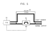
- FIG. 5 is a detailed circuit diagram illustrating a current limiter of FIG. 3 according to an exemplary embodiment of the present disclosure.
- FIG. 6 is a schematic current graph illustrating an operation of a current limiter of FIG. 5 according to an exemplary embodiment of the present disclosure.
- FIGS. 1-6 of the drawings like numerals being used for like and corresponding parts of the various drawings.
- Other features and advantages of the disclosed embodiments will be or will become apparent to one of ordinary skill in the art upon examination of the following figures and detailed description. It is intended that all such additional features and advantages be included within the scope of the disclosed embodiments, and protected by the accompanying drawings.
- the illustrated figures are only exemplary and not intended to assert or imply any limitation with regard to the environment, architecture, or process in which different embodiments may be implemented. Accordingly, the described aspect is intended to embrace all such alterations, modifications, and variations that fall within the scope and novel idea of the present invention.
- first a second constituent element
- first constituent element a first constituent element without departing from the scope and spirit of the present disclosure
- first constituent element may be denoted as a second constituent element.
- FIG. 3 is a schematic block diagram illustrating a protection coordination system according to an exemplary embodiment of the present disclosure.
- the protection coordination system is applicable to a general electric power distribution system that includes and illustrates a transformer ( 10 ) and circuit breakers ( 21 , 22 , 23 and 24 ), the constituent parts are not limited thereto, such that other parts irrelevant to the present disclosure will be omitted in detailed description and explanation thereto.
- the protection coordination system is applicable to a load line of an electric power distribution system, and includes, at each load line, first and second OCRs ( 31 and 32 ) and a current limiter ( 40 ).
- the second OCR ( 32 ) is arranged on a load line farther distanced from that of the first OCR ( 31 ), the placement of which has influence to an OCR curve.
- the relays are not limited thereto, and the number of relays may be determined based on the number of load lines.
- one current limiter ( 40 ) has been described in the present disclosure, it should be apparent to the skilled in the art that the current limiter is not limited thereto, and the number of current limiters may be determined based on the number of relays.
- FIG. 4 is a graph illustrating a protection coordination method according to an exemplary embodiment of the present disclosure, where instantaneous action and time action sections of the first and second OCRs ( 31 and 32 ), and an operation section of the current limiter ( 40 ) of FIG. 4 are exemplified, and it should be apparent that values of which are not limited thereto.
- first and second OCRs ( 31 and 32 ), and an operation section of the current limiter ( 40 ) of FIG. 4 are exemplified, and it should be apparent that values of which are not limited thereto.
- FIGS. 5 and 6 First, configuration and operation of the current limiter ( 40 ) will be described with reference to FIGS. 5 and 6 .
- FIG. 5 is a detailed circuit diagram illustrating a current limiter of FIG. 3 according to an exemplary embodiment of the present disclosure
- FIG. 6 is a schematic current graph illustrating an operation of a current limiter of FIG. 5 according to an exemplary embodiment of the present disclosure.
- the current limiter ( 40 ) includes an FFD (Fast Fault Detector, 51 ), a high speed switch ( 52 ) and a current limit resistor ( 53 ).
- the FFD ( 51 ) detects a fault current at a high speed, in a case the fault current is generated, and transmits an open signal to a high speed switch ( 52 ), where the high speed switch ( 52 ) so switches as to allow a main circuit is turned off by the open signal from the FFD ( 51 ).
- the current limit resistor ( 53 ) directly reduces a fault current detoured to a current limit circuit, in a case the fault current is generated, by the main circuit of the high speed switch ( 52 ) being turned off. Now, operation of the current limiter will be described.
- the FFD ( 51 ) set up in a predetermined value that determines whether there is generated a fault, detects the fault at a high speed, and transmits an open signal of the high speed switch ( 52 ) to the high speed switch ( 52 ).
- the current (normal current) flowing toward the high speed switch ( 52 ) closed under a normal state is such that, in a case a fault is generated, the high speed switch ( 52 ) is opened by the open signal transmitted from the FFD ( 51 ), and the fault current detours a path located with the current limit resistor ( 53 ), whereby strength of current is reduced as shown in a thick waveform of FIG. 6 .
- the current limiter ( 40 ) in the present disclosure shows a most fundamental current limiter, and is not limited thereto, other types of current limiters that include the same functions as those of the current limiter are not ruled out.
- the first OCR ( 31 ) is in an instantaneous operation section of 4,000 A or more
- the second OCR ( 32 ) is in an instantaneous operation section of 2,500 A or more.
- the current limiter ( 40 ) determines the current of 4,000 A or more as a fault current, there is no need of removing the fault current once for all and it suffices that the fault current up to the instantaneous operation section of the second OCR ( 32 ) be limited.
- the limitation of the fault current can be carried out by setting the current limit resistor ( 53 ) at a proper value with reference to FIG. 6 .
- the current limiter ( 40 ) limits the current from a point where the instantaneous operation section of the second OCR ( 32 ) starts to a point where the instantaneous operation section of the first OCR ( 31 ) starts. It should be apparent to the skilled in the art that the values in the present disclosure are just exemplary and the present disclosure is not restricted thereto.
- the current limiter ( 40 ) determines it as a fault current; the current limiter ( 40 ) limits the fault current to an arbitrary current from a point where the instantaneous operation section of the second OCR ( 32 ) starts (2,500 A of FIG. 4 ) to a point where the instantaneous operation section of the first OCR ( 31 ) starts (4,000 A of FIG. 4 ).
- the second OCR ( 32 ) carries out the instantaneous operation to operate at 0.04 second
- the first OCR ( 31 ) carries out the timer action at operate at 0.5 second. That is, there is generated a great time coordination difference to allow only the second OCR ( 32 ) to operate instantaneously, whereby only the section of FIG. 3 corresponding to ‘A’ section of FIG. 1 can be removed.
- the first OCR ( 31 ) cannot recognize the fault and maintains the normal state, whereby a section where protection coordination is disabled in the relays can be effectively removed.
Landscapes
- Engineering & Computer Science (AREA)
- Power Engineering (AREA)
- Emergency Protection Circuit Devices (AREA)
Applications Claiming Priority (2)
| Application Number | Priority Date | Filing Date | Title |
|---|---|---|---|
| KR1020110073227A KR101232976B1 (ko) | 2011-07-22 | 2011-07-22 | 보호협조 시스템 |
| KR10-2011-0073227 | 2011-07-22 |
Publications (2)
| Publication Number | Publication Date |
|---|---|
| US20130021707A1 US20130021707A1 (en) | 2013-01-24 |
| US8830646B2 true US8830646B2 (en) | 2014-09-09 |
Family
ID=46851276
Family Applications (1)
| Application Number | Title | Priority Date | Filing Date |
|---|---|---|---|
| US13/546,797 Active 2032-09-19 US8830646B2 (en) | 2011-07-22 | 2012-07-11 | Protection coordination system |
Country Status (5)
| Country | Link |
|---|---|
| US (1) | US8830646B2 (de) |
| EP (1) | EP2549609A3 (de) |
| JP (1) | JP5567624B2 (de) |
| KR (1) | KR101232976B1 (de) |
| CN (1) | CN102891480A (de) |
Families Citing this family (7)
| Publication number | Priority date | Publication date | Assignee | Title |
|---|---|---|---|---|
| KR101692245B1 (ko) * | 2014-06-24 | 2017-01-17 | 숭실대학교산학협력단 | 전력계통에서 순간저전압 개선을 위한 시스템 및 방법, 그 방법을 수행하기 위한 기록 매체 |
| KR101691928B1 (ko) * | 2014-10-01 | 2017-01-02 | 엘에스산전 주식회사 | 보호협조 시스템 및 보호협조 방법 |
| FR3041179B1 (fr) * | 2015-09-14 | 2019-05-10 | Schneider Electric Industries Sas | Dispositif et procede de limitation d'un premier pic de courant dans un reseau electrique |
| KR101890035B1 (ko) * | 2016-11-04 | 2018-08-21 | 한국전력공사 | 전력 계통의 보호 시스템 및 이의 동작 방법 |
| CN112771745B (zh) * | 2018-10-01 | 2023-08-25 | 三菱电机株式会社 | 直流配电系统 |
| KR20200112010A (ko) | 2019-03-20 | 2020-10-05 | 한국전력공사 | 초고속 스위칭 회로를 이용한 순간 전압 강하 방지 장치, 이의 방법, 및 이 방법을 저장한 컴퓨터 판독 가능 저장 매체 |
| WO2025113758A1 (en) * | 2023-11-27 | 2025-06-05 | Vestas Wind Systems A/S | A method for the protection of one or more power converters |
Citations (10)
| Publication number | Priority date | Publication date | Assignee | Title |
|---|---|---|---|---|
| US4724502A (en) * | 1983-12-16 | 1988-02-09 | Mitsubishi Denki Kabushiki Kaisha | Power transmission system with current limiting devices |
| JPH0446521A (ja) | 1990-06-11 | 1992-02-17 | Toshiba Corp | 配電システム |
| CN1059623A (zh) | 1990-09-03 | 1992-03-18 | 株式会社日立制作所 | 用于电力系统保护的方法及装置 |
| JPH10208954A (ja) | 1997-01-21 | 1998-08-07 | Takaoka Electric Mfg Co Ltd | 負荷時タップ切換器 |
| JP2000032662A (ja) | 1998-07-09 | 2000-01-28 | Takenaka Komuten Co Ltd | 受配電設備 |
| JP2000090788A (ja) | 1998-09-09 | 2000-03-31 | Toshiba Corp | 限流装置及び限流遮断装置 |
| JP2002010481A (ja) | 2000-06-20 | 2002-01-11 | Mitsubishi Electric Corp | 受配電保護システム |
| CN101505056A (zh) | 2008-02-05 | 2009-08-12 | Ls产电株式会社 | 峰值电流限制装置 |
| KR100961186B1 (ko) | 2008-05-20 | 2010-06-09 | 숭실대학교산학협력단 | 배전계통에 초전도 전류제한기 적용시 새로운 보호협조방법 |
| KR101044492B1 (ko) | 2010-04-23 | 2011-06-27 | 엘에스산전 주식회사 | 하이브리드 한류기 |
Family Cites Families (2)
| Publication number | Priority date | Publication date | Assignee | Title |
|---|---|---|---|---|
| FR2754115B1 (fr) * | 1996-10-01 | 1998-10-30 | Schneider Electric Sa | Dispositif de distribution electrique terminale a bloc limiteur hybride |
| FR2952470A1 (fr) * | 2009-11-06 | 2011-05-13 | Schneider Electric Ind Sas | Disjoncteur limiteur de courant, dispositif de distribution electrique pourvu d'un tel disjoncteur limiteur et procede de limitation de courant |
-
2011
- 2011-07-22 KR KR1020110073227A patent/KR101232976B1/ko active Active
-
2012
- 2012-07-04 EP EP12174893.3A patent/EP2549609A3/de not_active Withdrawn
- 2012-07-11 US US13/546,797 patent/US8830646B2/en active Active
- 2012-07-20 JP JP2012161393A patent/JP5567624B2/ja active Active
- 2012-07-20 CN CN201210254354XA patent/CN102891480A/zh active Pending
Patent Citations (10)
| Publication number | Priority date | Publication date | Assignee | Title |
|---|---|---|---|---|
| US4724502A (en) * | 1983-12-16 | 1988-02-09 | Mitsubishi Denki Kabushiki Kaisha | Power transmission system with current limiting devices |
| JPH0446521A (ja) | 1990-06-11 | 1992-02-17 | Toshiba Corp | 配電システム |
| CN1059623A (zh) | 1990-09-03 | 1992-03-18 | 株式会社日立制作所 | 用于电力系统保护的方法及装置 |
| JPH10208954A (ja) | 1997-01-21 | 1998-08-07 | Takaoka Electric Mfg Co Ltd | 負荷時タップ切換器 |
| JP2000032662A (ja) | 1998-07-09 | 2000-01-28 | Takenaka Komuten Co Ltd | 受配電設備 |
| JP2000090788A (ja) | 1998-09-09 | 2000-03-31 | Toshiba Corp | 限流装置及び限流遮断装置 |
| JP2002010481A (ja) | 2000-06-20 | 2002-01-11 | Mitsubishi Electric Corp | 受配電保護システム |
| CN101505056A (zh) | 2008-02-05 | 2009-08-12 | Ls产电株式会社 | 峰值电流限制装置 |
| KR100961186B1 (ko) | 2008-05-20 | 2010-06-09 | 숭실대학교산학협력단 | 배전계통에 초전도 전류제한기 적용시 새로운 보호협조방법 |
| KR101044492B1 (ko) | 2010-04-23 | 2011-06-27 | 엘에스산전 주식회사 | 하이브리드 한류기 |
Non-Patent Citations (5)
| Title |
|---|
| Japan Patent Office Application Serial No. 2012-161393, Office Action dated Feb. 4, 2014, 2 pages. |
| Japan Patent Office Application Serial No. 2012-161393, Office Action dated Sep. 17, 2013, 3 pages. |
| Kim, et al., "Method of Recloser-Fuse Coordination in a Power Distribution System With Superconducting Fault Current Limiter," IEEE Transactions on Applied Superconductivity, Vol. 20, No. 3, June 2010, pp. 1164-1167. |
| Korean Intellectual Property Office Application Serial No. 10-2011-0073227, Office Action dated Jul. 18, 2012, 4 pages. |
| The State Intellectual Property Office of the People's Republic of China Application Serial No. 201210254354.X, Office Action dated Apr. 23, 2014, 7 pages. |
Also Published As
| Publication number | Publication date |
|---|---|
| JP5567624B2 (ja) | 2014-08-06 |
| CN102891480A (zh) | 2013-01-23 |
| US20130021707A1 (en) | 2013-01-24 |
| EP2549609A3 (de) | 2018-01-10 |
| JP2013027306A (ja) | 2013-02-04 |
| KR20130011810A (ko) | 2013-01-30 |
| EP2549609A2 (de) | 2013-01-23 |
| KR101232976B1 (ko) | 2013-02-13 |
Similar Documents
| Publication | Publication Date | Title |
|---|---|---|
| US8830646B2 (en) | Protection coordination system | |
| CN109494703B (zh) | 一种基于补偿阻尼方式的主动干预型保安消弧方法 | |
| EP2975719B1 (de) | Schaltung zur fehlerstromermittlung | |
| EP2862252B1 (de) | Stromstationsschutzvorrichtung und verfahren zum schützen von stromstationen | |
| US11605948B2 (en) | Communication-based permissive protection scheme for power distribution networks | |
| CN106129954B (zh) | 断路器 | |
| US10074972B2 (en) | System and method of controlling current-limiters in ring systems | |
| CA2836030A1 (en) | System and method for fault protection | |
| CN102761095B (zh) | 欠压-过压保护装置及方法 | |
| US7535686B2 (en) | Control of circuit breakers in a multi-phase power system | |
| WO2019069247A1 (en) | PROTECTION AGAINST CIRCUIT BREAKER FAILURES IN AN ELECTRICAL SUBSTATION | |
| JP5189892B2 (ja) | サージ防護装置 | |
| JP5295635B2 (ja) | サージ防護装置 | |
| EP2945241B1 (de) | Fehlerstrombegrenzer | |
| US11336086B2 (en) | Current limiting circuit for limiting the magnitude of an alternating current | |
| US9954352B2 (en) | Power system including a circuit providing smart zone selective interlocking communication | |
| JP5220561B2 (ja) | サージ防護装置 | |
| CN108565835A (zh) | 发电机继电保护方法及电路 | |
| JP6698414B2 (ja) | 送電回線保護システム | |
| JP2020167774A (ja) | 保護装置 | |
| JP5335032B2 (ja) | 直流地絡検出装置、直流回路の地絡検出方法および直流電源の切り替え方法 | |
| GB2521143A (en) | An improved ring main unit | |
| US20110054713A1 (en) | Global trip unit | |
| KR101454295B1 (ko) | 한류 저항 소형화를 위한 한류기 | |
| KR101631637B1 (ko) | 한류기 |
Legal Events
| Date | Code | Title | Description |
|---|---|---|---|
| AS | Assignment |
Owner name: LSIS CO., LTD., KOREA, REPUBLIC OF Free format text: ASSIGNMENT OF ASSIGNORS INTEREST;ASSIGNORS:BANG, SEUNG HYUN;PARK, KWON BAE;CHOE, WON JOON;AND OTHERS;REEL/FRAME:028531/0613 Effective date: 20120702 |
|
| FEPP | Fee payment procedure |
Free format text: PAYOR NUMBER ASSIGNED (ORIGINAL EVENT CODE: ASPN); ENTITY STATUS OF PATENT OWNER: LARGE ENTITY |
|
| STCF | Information on status: patent grant |
Free format text: PATENTED CASE |
|
| MAFP | Maintenance fee payment |
Free format text: PAYMENT OF MAINTENANCE FEE, 4TH YEAR, LARGE ENTITY (ORIGINAL EVENT CODE: M1551) Year of fee payment: 4 |
|
| MAFP | Maintenance fee payment |
Free format text: PAYMENT OF MAINTENANCE FEE, 8TH YEAR, LARGE ENTITY (ORIGINAL EVENT CODE: M1552); ENTITY STATUS OF PATENT OWNER: LARGE ENTITY Year of fee payment: 8 |
|
| MAFP | Maintenance fee payment |
Free format text: PAYMENT OF MAINTENANCE FEE, 12TH YEAR, LARGE ENTITY (ORIGINAL EVENT CODE: M1553); ENTITY STATUS OF PATENT OWNER: LARGE ENTITY Year of fee payment: 12 |