US8844862B2 - Aft pylon fairing for aircraft engine suspension system, comprising a heat shield capable of expanding freely - Google Patents
Aft pylon fairing for aircraft engine suspension system, comprising a heat shield capable of expanding freely Download PDFInfo
- Publication number
- US8844862B2 US8844862B2 US13/653,042 US201213653042A US8844862B2 US 8844862 B2 US8844862 B2 US 8844862B2 US 201213653042 A US201213653042 A US 201213653042A US 8844862 B2 US8844862 B2 US 8844862B2
- Authority
- US
- United States
- Prior art keywords
- fairing
- engine
- deck
- heat protection
- along
- Prior art date
- Legal status (The legal status is an assumption and is not a legal conclusion. Google has not performed a legal analysis and makes no representation as to the accuracy of the status listed.)
- Active, expires
Links
- 239000000725 suspension Substances 0.000 title claims abstract description 42
- 238000006073 displacement reaction Methods 0.000 claims abstract description 11
- 239000003351 stiffener Substances 0.000 claims description 7
- 230000037431 insertion Effects 0.000 claims 1
- 238000003780 insertion Methods 0.000 claims 1
- 244000045947 parasite Species 0.000 description 4
- 230000004888 barrier function Effects 0.000 description 3
- 230000008901 benefit Effects 0.000 description 3
- 230000000930 thermomechanical effect Effects 0.000 description 3
- 230000015572 biosynthetic process Effects 0.000 description 2
- 239000002131 composite material Substances 0.000 description 2
- 230000000694 effects Effects 0.000 description 2
- 239000000446 fuel Substances 0.000 description 2
- 239000000463 material Substances 0.000 description 2
- 238000003466 welding Methods 0.000 description 2
- RTAQQCXQSZGOHL-UHFFFAOYSA-N Titanium Chemical compound [Ti] RTAQQCXQSZGOHL-UHFFFAOYSA-N 0.000 description 1
- 230000001944 accentuation Effects 0.000 description 1
- 230000000712 assembly Effects 0.000 description 1
- 238000000429 assembly Methods 0.000 description 1
- 230000015556 catabolic process Effects 0.000 description 1
- 239000000919 ceramic Substances 0.000 description 1
- 230000000295 complement effect Effects 0.000 description 1
- 230000006835 compression Effects 0.000 description 1
- 238000007906 compression Methods 0.000 description 1
- 238000006731 degradation reaction Methods 0.000 description 1
- 230000009970 fire resistant effect Effects 0.000 description 1
- 230000006872 improvement Effects 0.000 description 1
- 229910001026 inconel Inorganic materials 0.000 description 1
- 238000009434 installation Methods 0.000 description 1
- 238000004519 manufacturing process Methods 0.000 description 1
- 229910052751 metal Inorganic materials 0.000 description 1
- 239000002184 metal Substances 0.000 description 1
- 238000012986 modification Methods 0.000 description 1
- 230000004048 modification Effects 0.000 description 1
- 230000002035 prolonged effect Effects 0.000 description 1
- 238000005204 segregation Methods 0.000 description 1
- 229910001220 stainless steel Inorganic materials 0.000 description 1
- 239000010935 stainless steel Substances 0.000 description 1
- 239000010936 titanium Substances 0.000 description 1
- 229910052719 titanium Inorganic materials 0.000 description 1
Images



Classifications
-
- B—PERFORMING OPERATIONS; TRANSPORTING
- B64—AIRCRAFT; AVIATION; COSMONAUTICS
- B64D—EQUIPMENT FOR FITTING IN OR TO AIRCRAFT; FLIGHT SUITS; PARACHUTES; ARRANGEMENT OR MOUNTING OF POWER PLANTS OR PROPULSION TRANSMISSIONS IN AIRCRAFT
- B64D27/00—Arrangement or mounting of power plants in aircraft; Aircraft characterised by the type or position of power plants
- B64D27/02—Aircraft characterised by the type or position of power plants
- B64D27/10—Aircraft characterised by the type or position of power plants of gas-turbine type
- B64D27/12—Aircraft characterised by the type or position of power plants of gas-turbine type within, or attached to, wings
-
- B—PERFORMING OPERATIONS; TRANSPORTING
- B64—AIRCRAFT; AVIATION; COSMONAUTICS
- B64D—EQUIPMENT FOR FITTING IN OR TO AIRCRAFT; FLIGHT SUITS; PARACHUTES; ARRANGEMENT OR MOUNTING OF POWER PLANTS OR PROPULSION TRANSMISSIONS IN AIRCRAFT
- B64D29/00—Power-plant nacelles, fairings or cowlings
- B64D29/02—Power-plant nacelles, fairings or cowlings associated with wings
-
- B—PERFORMING OPERATIONS; TRANSPORTING
- B64—AIRCRAFT; AVIATION; COSMONAUTICS
- B64C—AEROPLANES; HELICOPTERS
- B64C7/00—Structures or fairings not otherwise provided for
- B64C7/02—Nacelles
-
- B—PERFORMING OPERATIONS; TRANSPORTING
- B64—AIRCRAFT; AVIATION; COSMONAUTICS
- B64D—EQUIPMENT FOR FITTING IN OR TO AIRCRAFT; FLIGHT SUITS; PARACHUTES; ARRANGEMENT OR MOUNTING OF POWER PLANTS OR PROPULSION TRANSMISSIONS IN AIRCRAFT
- B64D33/00—Arrangement in aircraft of power plant parts or auxiliaries not otherwise provided for
- B64D33/04—Arrangement in aircraft of power plant parts or auxiliaries not otherwise provided for of exhaust outlets or jet pipes
Definitions
- the invention may be used on any type of aircraft fitted with turbojets or turboprops.
- This type of suspension system also called an “EMS” (Engine Mounting Structure) can be used to suspend a turbo-engine below the aircraft wing, or to mount this turbojet above this wing.
- EMS Engine Mounting Structure
- the suspension system comprises a rigid structure also called the primary structure, often a ⁇ box>> type structure, in other words formed by the assembly of lower and upper spars and side panels connected to each other by cross stiffening ribs, in order to transmit forces.
- the system is also provided with suspension means inserted between the turbo-engine and the rigid structure, these means globally comprising two engine suspensions, and a system for resisting thrusts generated by the turbo-engine.
- this force resistance system normally comprises two side connecting rods connected firstly to an aft part of the turbojet fan casing, and secondly to an aft suspension fixed onto the central part of the turbojet.
- the suspension system also comprises another series of suspensions forming a suspension system inserted between the rigid structure and the aircraft wing, this system normally being composed of two or three suspensions.
- the pylon is provided with a plurality of secondary structures segregating and maintaining the systems while supporting pylon fairing elements, which are usually in the form of assemblies of panels added onto the structures.
- secondary structures are differentiated from the rigid structure by the fact that they are not designed to transfer forces from the engine to be transmitted to the aircraft wing.
- the secondary structures include the aft pylon fairing, also called the APF, that has a plurality of functions including the formation of a thermal or fire resistant barrier, and the formation of aerodynamic continuity between the engine exhaust and the suspension pylon.
- APF aft pylon fairing
- the heat protection deck is provided with an outer surface designed to delimit the engine core flow which is delimited by this deck, while the engine fan flow is delimited by the outer surfaces of the side panels, due to their location in the annular fan flow duct of the engine, and/or at the engine exhaust.
- the opposite ends of the heat protection deck are mounted fixed to the corresponding two side panels that also match the cross ribs. Alternately or simultaneously, the deck is fixed onto the cross ribs.
- the heat protection deck is in contact with the very hot core engine flow, which means that it deforms strongly due to thermal expansion.
- its corresponding embedments into the lower ends of the two side panels and/or the lower ends of the cross-ribs create high thermomechanical stresses within the deck and the elements into which it is embedded, which is obviously not good for these elements.
- the fairly cool fan flow is not directly delimited by the surface of the inner cross ribs due to their location inside the box, and the ribs may be sensitive to heat transferred from the heat protection deck with which they are in contact.
- the ribs may be sensitive to heat transferred from the heat protection deck with which they are in contact.
- it may be necessary to oversize them and/or to use expensive materials with good heat resistance properties to manufacture them.
- the deck is shifted from the transverse inner ribs by means of longitudinal walls, it being understood that these are the same walls that are indirectly used to mount the deck on the ribs.
- the deck is no longer mounted on the ribs directly, which advantageously allows the deck to deform more freely due to thermal expansion following the large amount of heat released by the core engine flow delimited by this deck.
- the purpose of the invention is to at least partially correct the disadvantages mentioned above relative to embodiments according to prior art.
- the purpose of the invention is an aft pylon fairing for an engine suspension system, that will be inserted between an aircraft wing and said engine, said fairing forming a box comprising a main structure extending along a longitudinal direction (X) of said fairing and integrating two side panels connected to each other, the fairing also comprising a heat protection deck provided with an outer surface that delimits a core engine flow from said engine, said heat protection deck being mounted on said main structure through connection means.
- connection means comprise a plurality of tabs each comprising a plane main portion, the width of which is oriented parallel to the transverse direction (Y) of the fairing, said plane portion being oriented such that in a section along any plane parallel to the longitudinal (X) and vertical (Z) directions passing through the plane main portion, this plane main portion is in the form of a straight segment locally orthogonal to said heat protection deck.
- said tabs are designed so that they can deform to accompany displacement of said heat protection deck relative to said main structure of the fairing if there is differential thermal expansion between these two entities.
- the solution disclosed in this invention can improve management of the differential thermal expansion between the main structure of the fairing and the deck, particularly along the length direction of the deck, namely approximately in the longitudinal direction.
- the tabs arranged in the manner defined above very satisfactorily accompany expansion of the thermal shield along its length direction, by strongly limiting or even entirely preventing parasite deformations of the deck along other directions.
- This deformation is then preferably in the form of curved tabs along lines parallel to the transverse direction corresponding to the preferred deformation mode of these tabs.
- the deck is not mounted rigidly on the main structure of the fairing, which advantageously allows it to deform more freely by thermal expansion as a result of the large heat quantities released by the core engine flow delimited by this deck. This is verified not only for deformation by expansion along the length direction, but also for deformation by expansion along the transverse direction.
- the particular orientation of the plane main portions of the tabs namely locally orthogonal to the heat protection deck, is capable of very satisfactorily resisting the acoustic pressure applied normal to the outside surface of this deck.
- the tabs are particularly well adapted to have good resistance to compression along the length direction of the plane portions and the high acoustic pressure encountered during some engine conditions, while allowing the required flexibility when they are stressed along the length direction of the deck during thermal expansion of the deck.
- said tabs are distributed in transverse rows, these rows being at a spacing from each other along the longitudinal (X) direction.
- the rows are capable of optimising thermal expansion of the deck along the transverse direction, without excessively stressing this deck.
- the tabs are preferably spaced from each other to enhance this benefit within each row.
- each tab has a first end arranged at the deck end, and a second end arranged at said main structure of the fairing.
- said first end preferably forms an integral part of the said plane main portion and is fixed onto a stiffener support itself fixed to the deck. Nevertheless, the stiffener is optional and a direct attachment would be possible without going outside the scope of the invention.
- said second end preferably prolongs said plane main portion, being curved along an axis of a curvature parallel to the transverse direction.
- the curvature can follow an arc of a circle.
- the deformation of each tab accompanying the thermal expansion of the deck is characterised by the accentuation of the curvature of the second end, and/or by the curvature of the plane main portion.
- each tab has a thickness of between 0.5 and 5 mm, and a total length of between 50 and 200 mm along the length direction of its plane main portion.
- the length of the plane main portion of each tab represents 50 to 95% of the total length of the tab, along the length direction of this plane main portion.
- the main structure of the fairing and the heat protection deck are fitted with stop means to block displacement of said heat protection deck relative to said main fairing structure, preferably along the X direction.
- said heat protection deck does not have any rigid mechanical connection directly with said side fairing panels.
- these panels are only added indirectly on the heat protection deck through tabs, themselves fixed to other elements of the main structure for connection of the two side panels. In other words, there is a longitudinal mechanical break between the deck and each of the side panels.
- Another purpose of the invention is an engine assembly comprising an engine such as a turbojet and a suspension system for this engine, this system complying with what has just been described.
- FIG. 2 shows a partial perspective view of the aft pylon fairing used on the suspension system shown in FIG. 1 , this fairing also being a purpose of this invention;
- FIG. 3 shows an enlarged perspective view of a part of the fairing shown in FIG. 2 , in a transverse section;
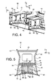
- FIG. 4 shows an enlarged perspective view of a part of the fairing shown in FIG. 2 , in a longitudinal section;
- FIG. 5 shows a cross-sectional view taken along line V-V in FIG. 2 ;
- FIG. 7 shows a view similar to the view in FIG. 6 , in a configuration adopted during operation of the engine, causing a differential thermal expansion between the heat protection deck and the main structure of the fairing.
- FIG. 1 shows an aircraft engine assembly 1 to be fixed under a wing 2 of this aircraft, this assembly comprising a suspension system 4 according to a preferred embodiment of this invention, and an engine 6 such as a turbojet suspended under this system 4 .
- the assembly 1 will be surrounded by a nacelle (not shown) and that the suspension system 4 comprises another series of suspensions (not shown) added onto the rigid structure 8 and that suspend this assembly 1 under the aircraft wing 2 .
- X is the longitudinal direction of the system 4 and is also effectively the longitudinal direction of the turbojet 6 and the longitudinal direction of the aft pylon fairing that will be presented below, this X direction being parallel to a longitudinal axis 5 of this turbojet 6 .
- the Y direction is oriented in the direction transverse to the system 4 and is also effectively the transverse direction of the turbojet 6 and the transverse direction of the aft pylon fairing, while Z is the vertical direction or the height, these three directions X, Y and Z being orthogonal to each other.
- FIG. 1 includes the two engine suspensions 10 , 12 , the thrust resistance system 14 , the rigid structure 8 of the suspension system 4 and a plurality of secondary structures added onto the rigid structure 8 . These secondary structures segregating and maintaining the systems while supporting pylon fairing elements will be described below.
- the rigid structure 8 is in the form of a box extending from the aft end towards the forward end, approximately along the X direction.
- the suspension means of this preferred embodiment comprise firstly the forward engine suspension 10 inserted between a forward end of the rigid structure 8 also called the pyramid, and an upper part of the fan casing 18 .
- the forward engine suspension 10 is designed conventionally in a manner known to those skilled in the art.
- the aft engine suspension 12 is inserted between the rigid structure 8 and the central casing 22 .
- the secondary structures of the pylon 4 include a forward pylon structure 24 , an aft pylon structure 26 , a connection fairing 28 for the forward and aft pylon structures, and an aft pylon fairing 30 , called the lower aft pylon fairing in this configuration in which the engine is located under the wing.
- the forward pylon structure 24 is placed in the lower forward extension of the wing 2 and above the primary structure 8 . It is mounted fixed onto the rigid structure 8 and it forms an aerodynamic profile between an upper part of the fan covers hinged on this part, and the leading edge of the wing.
- This forward pylon structure 24 then not only forms a pylon fairing, but is also used for placement, segregation and routing of the different systems (air, electrical, hydraulic, fuel).
- a heat exchanger is usually inserted in the space defined between these two elements.
- Aft Pylon Fairing 30 under the rigid structure 8 and the aft pylon structure 26 . It essentially forms a heat barrier also called a fire barrier that protects the pylon and the wing from heat dissipated by the core engine flow, and aerodynamic continuity between the engine exhaust and the suspension pylon.
- the fairing 30 mentioned above comprises a heat protection deck 32 provided with an outer surface that will delimit the core engine flow that the deck partially delimits radially outwards, this core engine flow output from the engine nozzle 33 being shown diagrammatically by the arrow 36 .
- the fairing 30 also comprises two side panels 44 with outer surfaces that delimit the fan flow from the engine shown diagrammatically by the arrow 38 , due to their location in the annular fan duct 40 of the fan flow from the engine, and/or at the engine exhaust.
- the heat protection deck 32 protecting the pylon and the wing from the core engine flow 36 forms a lower portion of the fairing 30 .
- this deck would form an upper portion of the fairing in the alternate case in which the engine is designed to be mounted above the wing.
- the forward end of the deck 32 matches the upper aft end of the nozzle 33 , or is very close to this aft end of nozzle 33 .
- the fairing 30 preferably comprises a plane of symmetry P corresponding to an XZ plane, this plane P also forming a vertical plane of symmetry for the entire suspension system 4 and for the engine 6 .
- the box-shaped aft pylon fairing 30 comprises the two side panels 44 each oriented approximately in an XZ plane on each side of the plane P. They are assembled to each other by an upper spar 45 , an intermediate spar 47 and inner transverse stiffener ribs 46 at a spacing from each other along the X direction, each of these ribs 46 being oriented along a YZ plane and for example being in the global form of a rectangle, a square or a U.
- the spars 45 , 47 also extend approximately parallel to each other along XY planes and are preferably perforated.
- the side panels 44 are installed fixed and directly onto the side portions of each of the inner ribs 46 by conventional means known to those skilled in the art. The same applies for their installation on the longitudinal edges of the spars 45 , 47 .
- the fairing 30 integrates the heat protection deck 32 in the lower part of the box, this deck also extending approximately parallel to the spars 45 , 47 .
- the fairing 30 is broken down into two distinct portions fixed to each other, namely a forward portion 50 forming the major part of the fairing, for example 60 to 85% of the fairing lengthwise along the X direction, and a small aft portion 52 globally in the form of a pyramid or a tip, the base of which is rigidly connected to the forward portion 50 , and the vertex 54 of which forms an aft end of the fairing 30 .
- the forward portion 50 has a fairly uniform cross-section along its entire length.
- the side panels 44 extend preferably each in a single piece from one end of the fairing 30 to the other, in other words both along the forward portion 50 and along the aft portion 52 .
- the heat protection deck 32 preferably extends in a single piece only along at least part of the forward portion 50 , and not along the aft portion 52 , although this could obviously be envisaged without going outside the scope of the invention. This special feature is explained particularly by the fact that the pyramid-shaped aft portion 52 progressively moves away from the centreline of the engine, such that the core engine flow that in any case loses some of its heat intensity as it moves in the aft direction, has less effect on the temperature of the lower closing element of the pyramid 52 .
- the ribs 46 are distributed into upper ribs connecting the spars 45 , 47 , and lower ribs extending the upper ribs downwards from the intermediate spar 47 .
- the upper ribs are square or rectangular in shape, while the lower ribs are in the form of an upside down U.
- These ribs 46 are preferably attached to the spars 45 , 47 using sole plates fitted on these ribs by welding or bolting. Their attachment to the side panels 44 may be made in a similar manner or directly on the edge of these ribs, also by welding or bolting.
- the spars 45 , 47 , the ribs 46 and the side panels 44 together form a main structure 60 , of which the component elements are rigidly fixed to each other.
- This structure 60 supports the deck 32 with some flexibility using connection means specific to this invention, which will now be described.
- These means comprise a plurality of metal tabs 62 , preferably made of stainless steel, distributed in transverse rows. These rows, for example three of them, are at a spacing from each other along the X direction. Each includes several tabs 62 parallel to each other and at a spacing from each other along the Y direction. For example, each row may comprise six tabs 62 .
- Each tab 62 has a constant width “l” and thickness “e”, values of the order of 10 to 100 mm may be adopted for the width and values of the order of 0.5 to 5 mm may be adopted for the thickness. These values are identical for each tab, unlike their length that can vary as a function of the geometry of the deck 32 that they support.
- Each tab comprises a first end 66 , which in this case is an integral part of the straight portion 64 . It is assembled on a stiffener support 68 preferably by bolting, the stiffener support 68 itself being welded onto the inner surface of the deck 32 . Note that the ends 66 of all tabs in the same row are assembled to the same stiffener support 68 , for example in the form of an upside down T section, and extending in the approximately transverse direction over the entire width of the deck 32 .
- the tab 62 also comprises a second end 72 that extends the plane portion 64 , with a curve preferably shaped like an arc of a circle, the axis of curvature of which is parallel to the Y direction.
- the curvature can result in an angle of about 90° between the plane portion 64 that it prolongs and the plane terminal part of the end 72 .
- the tab forms an upside down L, in which the base corresponding to the terminal part mentioned above is used for attachment on the intermediate spar 47 . More precisely, with reference to FIG. 5 , the terminal part of the end 72 bears in contact with the upper sole plate 76 of the lower rib 46 , itself bearing in contact with the intermediate spar 47 . Therefore the bolts used for attachment of the tab can pass through all these elements including the lower sole plate 78 of the upper rib 46 bearing on the spar 47 .
- the plane portion 64 represents 100% of the tab, it will be mounted directly on the web of the rib 46 .
- the tabs 62 alone suspend the deck 32 on the main structure 60 of the fairing. In particular, there is no direct rigid mechanical link between the side panels 44 and this deck, clearances 80 possibly being provided between these elements.
- FIG. 6 shows that the main structure 60 is equipped with a stop 82 at its forward end. This stop cooperates with a complementary stop 86 provided at the forward end of the deck 32 .
- the stops are in contact with each other or facing each other with a small clearance in order to limit the relative displacement along the X direction between the deck and the structure 60 , such a displacement being likely to occur due to the flexibility of the tabs 62 .
- the thermal expansion of the deck is greater than the thermal expansion of the main structure 60 for the reasons mentioned above.
- the tabs 62 accompany the relative displacement between these elements by deforming according to their preferred deformation mode, leading each of them to curve/bend along an axis parallel to the width, in other words parallel to the Y direction.
- the curvature may apply to the plane portion 64 and/or the second curved end 72 .
- FIG. 7 Such a configuration is shown in FIG. 7 , on which it can be seen that the deformation of the deck by expansion along the X direction takes place starting from the contact between the stops 82 , 86 that block this deck along this X direction.
- the tabs 62 accompany the relative displacement between these elements along the Y direction, deforming slightly along this Y direction. The fact that they are narrow facilitates this deformation.
- the orthogonality of the straight portions 64 of the tabs, locally with respect to the deck 32 , allows the deck to deform essentially along its length direction and therefore to limit vertical displacements.
- clearances between the deck 32 and the side panels are maintained even during engine operation phases during which the differential thermal expansion phenomenon described above occurs.
- the elements of the main structure 60 may be metallic or may be made of a composite material, while the deck itself is preferably metallic, for example made of titanium or Inconel. Nevertheless, other materials can be envisaged for this deck, for example ceramic, composite, etc.
Landscapes
- Engineering & Computer Science (AREA)
- Aviation & Aerospace Engineering (AREA)
- Chemical & Material Sciences (AREA)
- Combustion & Propulsion (AREA)
- Mechanical Engineering (AREA)
- Body Structure For Vehicles (AREA)
- Structures Of Non-Positive Displacement Pumps (AREA)
- Connection Of Plates (AREA)
Applications Claiming Priority (2)
| Application Number | Priority Date | Filing Date | Title |
|---|---|---|---|
| FR1159427A FR2981636B1 (fr) | 2011-10-19 | 2011-10-19 | Carenage aerodynamique arriere pour dispositif d'accrochage d'un moteur d'aeronef, comprenant un bouclier thermique capable de se dilater librement |
| FR1159427 | 2011-10-19 |
Publications (2)
| Publication Number | Publication Date |
|---|---|
| US20130105622A1 US20130105622A1 (en) | 2013-05-02 |
| US8844862B2 true US8844862B2 (en) | 2014-09-30 |
Family
ID=47002776
Family Applications (1)
| Application Number | Title | Priority Date | Filing Date |
|---|---|---|---|
| US13/653,042 Active 2033-01-26 US8844862B2 (en) | 2011-10-19 | 2012-10-16 | Aft pylon fairing for aircraft engine suspension system, comprising a heat shield capable of expanding freely |
Country Status (4)
| Country | Link |
|---|---|
| US (1) | US8844862B2 (de) |
| EP (1) | EP2583900B1 (de) |
| CN (1) | CN103057709B (de) |
| FR (1) | FR2981636B1 (de) |
Cited By (5)
| Publication number | Priority date | Publication date | Assignee | Title |
|---|---|---|---|---|
| US10551797B2 (en) | 2014-02-28 | 2020-02-04 | Timothy Bishop | Time display, method of presenting time information and timekeeping devices |
| US20210163143A1 (en) * | 2019-12-03 | 2021-06-03 | Airbus Operations Sas | Aft engine pylon fairing of an aircraft with multilayer heat shield |
| US20210380220A1 (en) * | 2019-02-26 | 2021-12-09 | Safran Nacelles | Expandable cellular system for a sandwich panel |
| US20230071244A1 (en) * | 2021-09-03 | 2023-03-09 | The Boeing Company | Heat shield assembly for use with an aircraft engine |
| US12459661B2 (en) | 2023-01-31 | 2025-11-04 | The Boeing Company | Heat shield for an aircraft and method of using the same |
Families Citing this family (25)
| Publication number | Priority date | Publication date | Assignee | Title |
|---|---|---|---|---|
| FR2981636B1 (fr) * | 2011-10-19 | 2013-12-27 | Airbus Operations Sas | Carenage aerodynamique arriere pour dispositif d'accrochage d'un moteur d'aeronef, comprenant un bouclier thermique capable de se dilater librement |
| FR2982845B1 (fr) * | 2011-11-22 | 2013-12-20 | Airbus Operations Sas | Carenage aerodynamique arriere de mat de moteur d'aeronef |
| FR2988688B1 (fr) * | 2012-03-27 | 2014-05-09 | Airbus Operations Sas | Carenage aerodynamique arriere a tenue en temperature amelioree pour mat d'accrochage d'ensemble propulsif d'aeronef |
| JP6114042B2 (ja) * | 2013-01-25 | 2017-04-12 | 三菱航空機株式会社 | 航空機の防火壁、パイロン、及び、航空機 |
| CA2901903C (en) * | 2013-03-06 | 2021-03-23 | Kevin Shephard | Aft pylon fairing for aircraft |
| US9404507B2 (en) * | 2013-04-15 | 2016-08-02 | Mra Systems, Inc. | Inner cowl structure for aircraft turbine engine |
| CN103612769B (zh) * | 2013-10-24 | 2016-09-21 | 中国商用飞机有限责任公司 | 翼吊布局飞机中吊挂的整流罩结构 |
| FR3013678B1 (fr) * | 2013-11-25 | 2015-11-20 | Airbus Operations Sas | Carenage aerodynamique |
| FR3014840B1 (fr) | 2013-12-17 | 2017-10-13 | Airbus Operations Sas | Ensemble pour aeronef comprenant un corps d'attache moteur equipe d'au moins une ferrure de support de manille penetrant dans le caisson du mat d'accrochage |
| FR3015431B1 (fr) * | 2013-12-19 | 2017-12-15 | Airbus Operations Sas | Structure primaire de mat d'accrochage renforcee. |
| FR3015433B1 (fr) | 2013-12-23 | 2016-02-12 | Airbus Operations Sas | Ensemble pour aeronef comprenant un mat d'accrochage integre a la nacelle et agence en partie arriere du fuselage |
| US10427778B2 (en) | 2016-03-14 | 2019-10-01 | The Boeing Company | Heat shield assembly and method |
| US10427776B2 (en) | 2016-07-27 | 2019-10-01 | The Boeing Company | Sliding joint kits, systems containing the same, and related methods |
| CN106314807B (zh) * | 2016-08-23 | 2018-08-21 | 西北工业大学 | 一种吸气式超燃冲压发动机的推力架结构 |
| FR3059300A1 (fr) * | 2016-11-30 | 2018-06-01 | Safran Nacelles | Carenage arriere de pylone de suspension du turboreacteur |
| FR3063068B1 (fr) * | 2017-02-23 | 2021-04-16 | Safran Nacelles | Carenage arriere de pylone en composite a matrice ceramique |
| FR3077269A1 (fr) * | 2018-02-01 | 2019-08-02 | Airbus Operations | Ensemble pour aeronef comprenant une structure primaire de mat d'accrochage fixee a un caisson de voilure a l'aide d'une liaison boulonnee |
| US10843787B2 (en) * | 2018-03-29 | 2020-11-24 | The Boeing Company | Heat shield assembly and mounting thereof on aircraft |
| FR3081443B1 (fr) * | 2018-05-22 | 2020-12-18 | Airbus Operations Sas | Aeronef comprenant au moins un capot equipe d’un systeme d’articulation ameliore |
| CN110920906B (zh) * | 2018-09-20 | 2026-02-10 | 空客(北京)工程技术中心有限公司 | 结构体、悬架系统、发动机组件和飞行器 |
| US11338902B2 (en) * | 2019-09-18 | 2022-05-24 | The Boeing Company | Heat shield for an aircraft |
| US12252245B2 (en) | 2021-01-20 | 2025-03-18 | The Boeing Company | Beaded composite structures and methods for manufacturing beaded composite structures |
| CN114671033B (zh) * | 2022-04-28 | 2023-01-17 | 中国航发沈阳发动机研究所 | 一种高隐身低尾阻轻质的非接触式飞发搭接结构 |
| FR3139117A1 (fr) * | 2022-08-30 | 2024-03-01 | Airbus Operations | Carenage ameliore de mât d’aeronef, ensemble de carenage, mât d’aeronef et aeronef. |
| FR3166885A1 (fr) * | 2024-09-30 | 2026-04-03 | Airbus Operations (S.A.S.) | Dispositif de protection thermique d’un longeron inférieur d’un caisson d’aéronef |
Citations (17)
| Publication number | Priority date | Publication date | Assignee | Title |
|---|---|---|---|---|
| US4238092A (en) * | 1978-08-17 | 1980-12-09 | Rohr Industries, Inc. | Accessory for a turbine engine |
| FR2832011A1 (fr) | 2001-11-05 | 2003-05-09 | Airbus France | Reseau de communication de type ethernet full duplex commute et procede de mise en oeuvre de celui-ci |
| US20030201366A1 (en) * | 2002-04-30 | 2003-10-30 | Connelly Thomas J. | Hybrid exhaust heat shield for pylon mounted gas turbine engines |
| US20070102494A1 (en) * | 2004-03-31 | 2007-05-10 | The Boeing Company | Superplastic forming of titanium assemblies |
| US20080067292A1 (en) * | 2006-09-18 | 2008-03-20 | Airbus France | Vortex generator at hot gas output |
| US20080217467A1 (en) * | 2005-07-29 | 2008-09-11 | Laurent Lafont | Assembly For Aircraft Comprising a Wing System Element as Well as an Attachment Mast |
| US20080224018A1 (en) * | 2005-09-28 | 2008-09-18 | Airbus France | Engine Assembly for an Aircraft Comprising an Engine as Well as an Engine Mounting Stucture |
| US20080245926A1 (en) * | 2005-09-28 | 2008-10-09 | Airbus France | Engine Assembly for an Aircraft Comprising an Engine as Well as an Engine Mounting Structure for Such an Engine |
| US7445179B2 (en) * | 2005-09-28 | 2008-11-04 | Airbus France | Engine assembly for aircraft |
| FR2920623A1 (fr) | 2007-09-03 | 2009-03-06 | Airbus France Sa | Dispositif de commutation de trames pour reseau afdx. |
| WO2009037267A1 (fr) | 2007-09-20 | 2009-03-26 | Airbus France | Carenage aerodynamique arriere inferieur pour dispositif d'accrochage d'un moteur d'aeronef |
| US20090095443A1 (en) * | 2007-10-11 | 2009-04-16 | The Boeing Company | Ceramic Heat Shield |
| US20090200418A1 (en) * | 2006-05-16 | 2009-08-13 | Airbus France | Device for attaching an aircraft engine |
| US20100051743A1 (en) * | 2007-03-16 | 2010-03-04 | Airbus Operations | Rear lower aerodynamic fairing for the attachment device of an aircraft engine |
| US20110011972A1 (en) * | 2008-03-28 | 2011-01-20 | Aircelle | Primary structure of a connecting strut |
| US20120080554A1 (en) * | 2010-10-01 | 2012-04-05 | Airbus Operations (S.A.S.) | Aircraft engine attachment pylon comprising two front wing system attachments with orthogonal shearing pins |
| US20130105622A1 (en) * | 2011-10-19 | 2013-05-02 | Airbus Operations (Sas) | Aft pylon fairing for aircraft engine suspension system, comprising a heat shield capable of expanding freely |
Family Cites Families (2)
| Publication number | Priority date | Publication date | Assignee | Title |
|---|---|---|---|---|
| FR2878229B1 (fr) * | 2004-11-23 | 2008-04-18 | Airbus France Sas | Systeme de fixation d'un mat de moteur a l'aile d'un aeronef |
| FR2891256B1 (fr) * | 2005-09-27 | 2007-10-26 | Airbus France Sas | Dispositif d'accrochage d'un moteur interpose entre une voilure d'aeronef et ledit moteur |
-
2011
- 2011-10-19 FR FR1159427A patent/FR2981636B1/fr not_active Expired - Fee Related
-
2012
- 2012-10-16 EP EP12188622.0A patent/EP2583900B1/de active Active
- 2012-10-16 US US13/653,042 patent/US8844862B2/en active Active
- 2012-10-19 CN CN201210401360.3A patent/CN103057709B/zh not_active Expired - Fee Related
Patent Citations (27)
| Publication number | Priority date | Publication date | Assignee | Title |
|---|---|---|---|---|
| US4238092A (en) * | 1978-08-17 | 1980-12-09 | Rohr Industries, Inc. | Accessory for a turbine engine |
| FR2832011A1 (fr) | 2001-11-05 | 2003-05-09 | Airbus France | Reseau de communication de type ethernet full duplex commute et procede de mise en oeuvre de celui-ci |
| US7352744B2 (en) * | 2001-11-05 | 2008-04-01 | Airbus France S.A.S. | Switched full-duplex ethernet type communication network and implementation process for this network |
| US20030201366A1 (en) * | 2002-04-30 | 2003-10-30 | Connelly Thomas J. | Hybrid exhaust heat shield for pylon mounted gas turbine engines |
| US20070102494A1 (en) * | 2004-03-31 | 2007-05-10 | The Boeing Company | Superplastic forming of titanium assemblies |
| US20080217467A1 (en) * | 2005-07-29 | 2008-09-11 | Laurent Lafont | Assembly For Aircraft Comprising a Wing System Element as Well as an Attachment Mast |
| US8061649B2 (en) * | 2005-09-28 | 2011-11-22 | Airbus Operations Sas | Engine assembly for an aircraft comprising an engine as well as an engine mounting structure for such an engine |
| US20080224018A1 (en) * | 2005-09-28 | 2008-09-18 | Airbus France | Engine Assembly for an Aircraft Comprising an Engine as Well as an Engine Mounting Stucture |
| US20080245926A1 (en) * | 2005-09-28 | 2008-10-09 | Airbus France | Engine Assembly for an Aircraft Comprising an Engine as Well as an Engine Mounting Structure for Such an Engine |
| US20080251633A1 (en) * | 2005-09-28 | 2008-10-16 | Airbus France | Engine Assembly for an Aircraft Comprising an Engine as Well as an Engine Mounting Structure for Such an Engine |
| US7445179B2 (en) * | 2005-09-28 | 2008-11-04 | Airbus France | Engine assembly for aircraft |
| US7971826B2 (en) * | 2005-09-28 | 2011-07-05 | Airbus Operations Sas | Engine assembly for an aircraft comprising an engine as well as an engine mounting structure for such an engine |
| US7797947B2 (en) * | 2005-09-28 | 2010-09-21 | Airbus France | Mounting assembly for securing an engine to an aircraft wing |
| US20090200418A1 (en) * | 2006-05-16 | 2009-08-13 | Airbus France | Device for attaching an aircraft engine |
| US20080067292A1 (en) * | 2006-09-18 | 2008-03-20 | Airbus France | Vortex generator at hot gas output |
| US7988092B2 (en) * | 2006-09-18 | 2011-08-02 | Airbus Operations Sas | Vortex generator at hot gas output |
| US8118252B2 (en) * | 2007-03-16 | 2012-02-21 | Airbus Operations Sas | Rear lower aerodynamic fairing for the attachment device of an aircraft engine |
| US20100051743A1 (en) * | 2007-03-16 | 2010-03-04 | Airbus Operations | Rear lower aerodynamic fairing for the attachment device of an aircraft engine |
| US20100284313A1 (en) * | 2007-09-03 | 2010-11-11 | AIRBUS OPERATIONS (inc. as a Soc. par ACT. Simpl.) | Frame switching device |
| FR2920623A1 (fr) | 2007-09-03 | 2009-03-06 | Airbus France Sa | Dispositif de commutation de trames pour reseau afdx. |
| US20110155847A1 (en) * | 2007-09-20 | 2011-06-30 | Frederic Journade | Aft pylon fairing for an aircraft engine suspension system |
| EP2190739A1 (de) | 2007-09-20 | 2010-06-02 | Airbus Operations | Untere hinterseitige aerodynamische verkleidung für eine flugzeugmotorbefestigungsvorrichtung |
| WO2009037267A1 (fr) | 2007-09-20 | 2009-03-26 | Airbus France | Carenage aerodynamique arriere inferieur pour dispositif d'accrochage d'un moteur d'aeronef |
| US20090095443A1 (en) * | 2007-10-11 | 2009-04-16 | The Boeing Company | Ceramic Heat Shield |
| US20110011972A1 (en) * | 2008-03-28 | 2011-01-20 | Aircelle | Primary structure of a connecting strut |
| US20120080554A1 (en) * | 2010-10-01 | 2012-04-05 | Airbus Operations (S.A.S.) | Aircraft engine attachment pylon comprising two front wing system attachments with orthogonal shearing pins |
| US20130105622A1 (en) * | 2011-10-19 | 2013-05-02 | Airbus Operations (Sas) | Aft pylon fairing for aircraft engine suspension system, comprising a heat shield capable of expanding freely |
Non-Patent Citations (2)
| Title |
|---|
| "AFDX protocol tutorial," http://sierrasales.com/pdfs/AFDXTutorial.pdf, 2005, Condor Engineering, Santa Barbara, California, United States. |
| French Search Report for Application No. FR 1159427 dated May 24, 2012. |
Cited By (7)
| Publication number | Priority date | Publication date | Assignee | Title |
|---|---|---|---|---|
| US10551797B2 (en) | 2014-02-28 | 2020-02-04 | Timothy Bishop | Time display, method of presenting time information and timekeeping devices |
| US20210380220A1 (en) * | 2019-02-26 | 2021-12-09 | Safran Nacelles | Expandable cellular system for a sandwich panel |
| US11932399B2 (en) * | 2019-02-26 | 2024-03-19 | Safran Nacelles | Expandable cellular system for a sandwich panel |
| US20210163143A1 (en) * | 2019-12-03 | 2021-06-03 | Airbus Operations Sas | Aft engine pylon fairing of an aircraft with multilayer heat shield |
| US20230071244A1 (en) * | 2021-09-03 | 2023-03-09 | The Boeing Company | Heat shield assembly for use with an aircraft engine |
| US11781482B2 (en) * | 2021-09-03 | 2023-10-10 | The Boeing Company | Heat shield assembly for use with an aircraft engine |
| US12459661B2 (en) | 2023-01-31 | 2025-11-04 | The Boeing Company | Heat shield for an aircraft and method of using the same |
Also Published As
| Publication number | Publication date |
|---|---|
| FR2981636A1 (fr) | 2013-04-26 |
| EP2583900B1 (de) | 2016-03-30 |
| EP2583900A3 (de) | 2014-12-10 |
| CN103057709B (zh) | 2016-01-27 |
| EP2583900A2 (de) | 2013-04-24 |
| US20130105622A1 (en) | 2013-05-02 |
| CN103057709A (zh) | 2013-04-24 |
| FR2981636B1 (fr) | 2013-12-27 |
Similar Documents
| Publication | Publication Date | Title |
|---|---|---|
| US8844862B2 (en) | Aft pylon fairing for aircraft engine suspension system, comprising a heat shield capable of expanding freely | |
| US8662440B2 (en) | AFT pylon fairing for an aircraft engine suspension system | |
| US7971826B2 (en) | Engine assembly for an aircraft comprising an engine as well as an engine mounting structure for such an engine | |
| RU2401222C2 (ru) | Силовая установка летательного аппарата, содержащая двигатель и стойку его крепления | |
| US7988092B2 (en) | Vortex generator at hot gas output | |
| US8739552B2 (en) | Structural nacelle | |
| US8118252B2 (en) | Rear lower aerodynamic fairing for the attachment device of an aircraft engine | |
| US9435224B2 (en) | Method for cooling a thermal protection floor of an aft aerodynamic fairing of a structure for mounting an aircraft propulsion system | |
| RU2424949C2 (ru) | Силовая установка летательного аппарата, содержащая двигатель, а также устройство крепления такого двигателя | |
| US8607453B2 (en) | Method of manufacture by superplastic forming and by fishplating of a rib for an aerodynamic fairing of an aircraft engine mounting pylon | |
| US8579231B2 (en) | Method of manufacture by superplastic forming and by fishplating of a rib for an aerodynamic fairing of an aircraft engine mounting pylon | |
| JP6920054B2 (ja) | 性能強化型のジェットエンジン装着支柱 | |
| US7677493B2 (en) | Engine assembly for aircraft comprising an engine and a mounting device for such an engine | |
| US9975641B2 (en) | Aircraft propelling assembly including a duct forming a thermal barrier integrated in the caisson of the rigid structure of the engine mounting system | |
| GB2544624A (en) | An aircraft engine assembly comprising at least two rear engine attachments axially shifted from each other | |
| US7967242B2 (en) | Engine mounting structure interposed between an aircraft wing system and said engine | |
| EP3254953A1 (de) | Wärmeisolationsfolie | |
| US20130320135A1 (en) | Aft aerodynamic fairing with improved thermal resistance for a pylon for attaching an aircraft propelling assembly | |
| US20200094980A1 (en) | Structure, suspension system, engine assembly and aircraft |
Legal Events
| Date | Code | Title | Description |
|---|---|---|---|
| AS | Assignment |
Owner name: AIRBUS OPERATIONS (S.A.S.), FRANCE Free format text: ASSIGNMENT OF ASSIGNORS INTEREST;ASSIGNOR:JOURNADE, FREDERIC;REEL/FRAME:029598/0181 Effective date: 20121212 |
|
| FEPP | Fee payment procedure |
Free format text: PAYOR NUMBER ASSIGNED (ORIGINAL EVENT CODE: ASPN); ENTITY STATUS OF PATENT OWNER: LARGE ENTITY |
|
| STCF | Information on status: patent grant |
Free format text: PATENTED CASE |
|
| MAFP | Maintenance fee payment |
Free format text: PAYMENT OF MAINTENANCE FEE, 4TH YEAR, LARGE ENTITY (ORIGINAL EVENT CODE: M1551) Year of fee payment: 4 |
|
| MAFP | Maintenance fee payment |
Free format text: PAYMENT OF MAINTENANCE FEE, 8TH YEAR, LARGE ENTITY (ORIGINAL EVENT CODE: M1552); ENTITY STATUS OF PATENT OWNER: LARGE ENTITY Year of fee payment: 8 |