US8855357B2 - Speaker diaphragm and speaker using same, and electronic equipment and device using said speaker, and speaker diaphragm manufacturing method - Google Patents
Speaker diaphragm and speaker using same, and electronic equipment and device using said speaker, and speaker diaphragm manufacturing method Download PDFInfo
- Publication number
- US8855357B2 US8855357B2 US13/511,160 US201113511160A US8855357B2 US 8855357 B2 US8855357 B2 US 8855357B2 US 201113511160 A US201113511160 A US 201113511160A US 8855357 B2 US8855357 B2 US 8855357B2
- Authority
- US
- United States
- Prior art keywords
- speaker
- fiber
- diaphragm
- fiber material
- bamboo
- Prior art date
- Legal status (The legal status is an assumption and is not a legal conclusion. Google has not performed a legal analysis and makes no representation as to the accuracy of the status listed.)
- Expired - Fee Related, expires
Links
Images

Classifications
-
- H—ELECTRICITY
- H04—ELECTRIC COMMUNICATION TECHNIQUE
- H04R—LOUDSPEAKERS, MICROPHONES, GRAMOPHONE PICK-UPS OR LIKE ACOUSTIC ELECTROMECHANICAL TRANSDUCERS; ELECTRIC HEARING AIDS; PUBLIC ADDRESS SYSTEMS
- H04R31/00—Apparatus or processes specially adapted for the manufacture of transducers or diaphragms therefor
- H04R31/003—Apparatus or processes specially adapted for the manufacture of transducers or diaphragms therefor for diaphragms or their outer suspension
-
- H—ELECTRICITY
- H04—ELECTRIC COMMUNICATION TECHNIQUE
- H04R—LOUDSPEAKERS, MICROPHONES, GRAMOPHONE PICK-UPS OR LIKE ACOUSTIC ELECTROMECHANICAL TRANSDUCERS; ELECTRIC HEARING AIDS; PUBLIC ADDRESS SYSTEMS
- H04R7/00—Diaphragms for electromechanical transducers; Cones
- H04R7/02—Diaphragms for electromechanical transducers; Cones characterised by the construction
- H04R7/12—Non-planar diaphragms or cones
-
- H—ELECTRICITY
- H04—ELECTRIC COMMUNICATION TECHNIQUE
- H04R—LOUDSPEAKERS, MICROPHONES, GRAMOPHONE PICK-UPS OR LIKE ACOUSTIC ELECTROMECHANICAL TRANSDUCERS; ELECTRIC HEARING AIDS; PUBLIC ADDRESS SYSTEMS
- H04R2307/00—Details of diaphragms or cones for electromechanical transducers, their suspension or their manufacture covered by H04R7/00 or H04R31/003, not provided for in any of its subgroups
- H04R2307/021—Diaphragms comprising cellulose-like materials, e.g. wood, paper, linen
-
- H—ELECTRICITY
- H04—ELECTRIC COMMUNICATION TECHNIQUE
- H04R—LOUDSPEAKERS, MICROPHONES, GRAMOPHONE PICK-UPS OR LIKE ACOUSTIC ELECTROMECHANICAL TRANSDUCERS; ELECTRIC HEARING AIDS; PUBLIC ADDRESS SYSTEMS
- H04R2499/00—Aspects covered by H04R or H04S not otherwise provided for in their subgroups
- H04R2499/10—General applications
- H04R2499/13—Acoustic transducers and sound field adaptation in vehicles
-
- Y—GENERAL TAGGING OF NEW TECHNOLOGICAL DEVELOPMENTS; GENERAL TAGGING OF CROSS-SECTIONAL TECHNOLOGIES SPANNING OVER SEVERAL SECTIONS OF THE IPC; TECHNICAL SUBJECTS COVERED BY FORMER USPC CROSS-REFERENCE ART COLLECTIONS [XRACs] AND DIGESTS
- Y10—TECHNICAL SUBJECTS COVERED BY FORMER USPC
- Y10T—TECHNICAL SUBJECTS COVERED BY FORMER US CLASSIFICATION
- Y10T29/00—Metal working
- Y10T29/49—Method of mechanical manufacture
- Y10T29/49002—Electrical device making
- Y10T29/49005—Acoustic transducer
Definitions
- the present invention relates to a diaphragm of speakers to be used in a variety of audio equipment and video equipment, and electronic devices as well as automobiles, using the same diaphragm, such as speakers, stereos, and television receivers, and the present invention also relates to a method of manufacturing the same diaphragm of speakers.
- the paper diaphragms many of which are formed of craft paper made from conifer have generally a lower rigidity than diaphragm formed of metal material or resin material. It is thus difficult for the paper diaphragm to improve the rigidity from the material view of point.
- the speaker employing the paper diaphragm is thus disadvantaged in clearer sound reproduction that is one of the factors in quality sound, as well as in larger output and in higher reliability.
- Patent Literature Unexamined Japanese Patent Application Publication No. 2007-221635
- the diaphragm of the present invention improves material rigidity, produces low-bass sound with firm feeling in a low register, and provides clear sound having less resonance peculiar to a high register and caused by lack of rigidity in the diaphragm. On top of that, the present invention allows the diaphragm to output larger sound and to be highly reliable.
- the diaphragm of the present invention is formed of a first fiber material and a second fiber material, the first fiber material is beaten to have a given freeness, and the second fiber material is obtained by carbonizing bamboo-fiber that has been fibrillated into a microfibril state, and the first and the second fiber materials are milled into the paper for the diaphragm. This structure allows the second fiber material to increase the rigidity and also increase internal loss, so that the sound quality of the speaker employing this diaphragm can be improved.
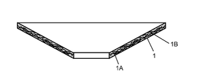
- FIG. 1 is a schematic sectional view of a speaker diaphragm in accordance with an embodiment of the present invention.
- FIG. 2 is a sectional view of a speaker in accordance with an embodiment of the present invention.
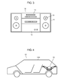
- FIG. 3 shows an appearance of an electronic device in accordance with an embodiment of the present invention.
- FIG. 4 is a sectional view of equipment in accordance with an embodiment of the present invention.
- FIG. 1 is a sectional view of a diaphragm in accordance with the embodiment of the present invention.
- Diaphragm 1 contains first fiber material 1 A that is beaten to have a given freeness and second fiber material 1 B that is obtained by carbonizing bamboo fiber fibrillated into a microfibril state.
- Diaphragm 1 can contain materials other than first and second fiber materials 1 A and 1 B, e.g. it can contain bamboo fiber.
- First fiber material 1 A can employ bamboo fiber instead of conifer, whereby adverse affect to terrestrial environment can be decreased.
- Diaphragm 1 is made of paper manufactured from these materials.
- FIG. 1 shows an outline of diaphragm 1 with straight lines, and for the convenience of description, it seems that spaces are available between the outlines, first fiber material 1 A, and second fiber material 1 B. However, in a case where diaphragm 1 is formed only of first fiber material 1 A and second fiber material 1 B, they are filled in places other than the places they are illustrated.
- a freeness of first fiber material 1 A is not greater than 650 cc.
- a freeness can be measured by a method specified under ISO 5267-2.
- a freeness of second fiber material 1 B preferably is not greater than 15 cc. This combination of the degrees of beating allows improving the intertwining between the fibers.
- a freeness of the bamboo fiber that is fibrillated into a microfibril state can be measured practically 1 cc at best, so that the lower limit of a freeness of second fiber material 1 B is 1 cc.
- Second fiber material 1 B preferably has an average fiber diameter of smaller than 5 ⁇ m.
- a smaller average fiber diameter allows improving the intertwining state of fibers.
- An average fiber diameter greater than 5 ⁇ m still allows providing diaphragm 1 with merits of bamboo fiber; however, it weakens the power to strengthen the intertwining. Meanwhile even the bamboo fiber is beaten into a microfibril state, its average fiber diameter can decrease to approx. 1 ⁇ m at best.
- a ratio of average fiber length L to average fiber diameter D i.e. L/D, is preferably equal to or greater than 10.
- a greater L/D allows improving the intertwining state of fibers. Even when the bamboo fiber is finely beaten into microfibril state, the L/D of bamboo fiber can be increased practically as much as approx. 2000.
- the upper limit of the L/B of second fiber material 1 B is 2000.
- Second fiber material 1 B is preferably mixed into diaphragm 1 in an amount of not smaller than 5 wt % and not greater than 50 wt %. In a case of smaller than 5 wt %, the rigidity of diaphragm 1 increases a little. On the other hand, when second fiber material 1 B is mixed into diaphragm 1 in an amount of greater than 50 wt %, water leakage is greatly lowered, so that the paper milling takes a longer time and the productivity is thus lowered.
- first fiber material 1 A includes the bamboo fiber fibrillated into the microfibril state
- second fiber material 1 B is mixed into diaphragm 1 preferably in an amount ranging from 5 wt % to 50 wt % (inclusive). The reason of this amount is the same as discussed previously.
- the bamboo fiber used in this embodiment is not limited to a specific one as far as it originates in plant and has grown up and is aged longer than one year.
- a bamboo shoot or a young bamboo aged shorter than one year should be excluded.
- the bamboo aged longer than one year can maintain at minimum the rigidity and the sturdiness required in this embodiment, and the bamboo aged longer than two years improves the rigidity and the sturdiness.
- the bamboo aged longer than three years can further improves the rigidity and the sturdiness.
- Second fiber material 1 B is obtained by beating the foregoing bamboo fiber into the microfibril state and then carbonizing it. Material 1 B thus increases its rigidity from a state before the carbonization, and as a result, diaphragm 1 increases the rigidity.
- diaphragm 1 improves its rigidity and sturdiness.
- the bamboo fiber in the microfibril state is carbonized to such a degree that can provide diaphragm 1 with appropriate rigidity.
- the carbonizing process maintains the shape but increases the rigidity of the bamboo fiber.
- An excessive carbonization cannot maintain the shape as fiber, so that it is important to control a temperature and a time of the carbonizing process. For instance, heat treating at the temperature ranging from 500° C. to 1000° C. (inclusive) and for the time ranging from 24 hours to 120 hours (inclusive) will form second fiber material 1 B suitable for diaphragm 1 of the speakers to be used for acoustic application or for vehicle equipment.
- the carbonization discussed above allows the bamboo fiber to increase its elastic coefficient and internal loss, so that synergistic effect can be produced for the speakers to improve the sound quality.
- the sound can be reproduced more clearly, a low-bass sound with firm feeling in a low register can be reproduced, and a clear sound having less resonance peculiar to a high register and caused by lack of rigidity in the diaphragm can be reproduced.
- a sound pressure in a high register is improved, and a reproduction band is widened.
- first fiber material 1 A and second fiber material 1 B produces the following acoustic advantages: a sound pressure in the high register is improved, a clear and powerful sound is obtained in the high register, a low-bass sound with firm feeling is reproduced in a low register, and as a whole, a sound with high articulation, clear sonic contours, and excellence in auditory lateralization can be achieved.
- a comparison with a diaphragm simply made of paper-pulp proves that diaphragm 1 is more excellent in quality and reliability because the sturdiness of diaphragm 1 is improved.
- Use of this diaphragm 1 allows a speaker to withstand a large input, and use of the speaker having this diaphragm 1 allows improving various reliabilities such as moist resistance that is an important factor to an in-car speaker.
- Diaphragm 1 thus allows the speaker to improve sound quality, to withstand a large output, and to increase the reliability.
- use of the bamboo fiber reduces the cost and is friendly to terrestrial environment.
- the bamboo fiber is beaten further, and this fiber is used as first fiber material 1 A for being milled together with second fiber material 1 B, whereby advantages of the bamboo fiber can be further exerted. If reinforcing materials other than the bamboo fiber is contained, they can be milled together with the bamboo fiber beaten into microfibril state, whereby the binding force can be strengthened and the advantages of the bamboo fiber can be exerted.
- a fiber disintegration step can be prepared as a pre-process where fiber material is disintegrated for progressing in the degree of beating.
- This pre-process will improve the productivity even when the degree of beating has been progressed, and also achieves adjusting the sound quality with high accuracy.
- the effect of this pre-process is advantageous particularly at the use of the material having high rigidity such as the bamboo fiber.
- Mica or aramid fiber can be used as the reinforcing material.
- Use of mica will increase the elastic coefficient and the internal loss, and use of aramid fiber will increase heat resistance and tensile strength.
- Two or more than two of the foregoing reinforcing materials can be used.
- additive such as sizing agent, paper strength additive, binder, waterproof agent, pigment, or dyestuff can be used.
- Polylactic acid and polyvinyl alcohol are compatible with the cellulose of bamboo fiber, so that they are easily fixed to the surface of bamboo fiber. They are also expected to increase the internal loss, and they can thus improve the frequency characteristics of the speaker.
- Polylactic acid in particular, is biodegradable plastic, so that the diaphragm made of bamboo fiber and polylactic acid is environmental harmonic and aids a speaker in being terrestrial environment friend.
- Use of the pigment, dyestuff, sizing agent, or paper strength additive is not specifically limited.
- diaphragm 1 is made by milling first fiber material 1 A together with second fiber material 1 B, and the first fiber material 1 A processed to have a given deeper degree, and the second fiber material 1 B is bamboo fiber fibrillated into the microfibril state and then carbonized.
- the carbonized second fiber material 1 B in particular allows diaphragm 1 to have a high internal loss while it still maintains high elastic coefficient.
- Speaker 10 includes magnetic circuit 5 , frame 7 , diaphragm 1 , and voice coil 8 .
- Internal-magnet type magnetic circuit 5 is formed of magnetized magnet 2 sandwiched by upper plate 3 and yoke 4 .
- Frame 7 is joined to yoke 4 of magnetic circuit 5 .
- Outer circumference of diaphragm 1 is bonded to a periphery of frame 7 via edge 9 .
- frame 7 supports the outer circumference of diaphragm 1 .
- a first end of voice coil 8 is joined to a center part of diaphragm 1 , and a second end of voice coil 8 is inserted into magnetic gap 6 . Parts of voice coil 8 are thus disposed within a working range of magnetic flux generated from magnetic circuit 5 .
- diaphragm 1 is used in speaker 10 having the internal-magnet type magnetic circuit 5 ; however, it can be used in a speaker having an outer-magnet type magnetic circuit.
- diaphragm 1 allows speaker 10 to improve the sound quality, to be more specific, the sound can be reproduced more clearly, a low-bass sound with firm feeling in a low register can be reproduced, and a clear sound having less resonance peculiar to a high register and caused by lack of rigidity in the diaphragm can be reproduced. On top of that, a sound pressure in a high register is improved, and a reproduction band is widened.
- FIG. 3 shows an appearance of a mini-component stereo system as a representative of the electronic device in accordance with this embodiment.
- Speaker 10 is integrated into enclosure 11 , thereby forming a speaker system.
- Amplifier 12 includes an amplifying circuit for electric signals supplied to the speaker system.
- Operating section 13 including a player outputs a source connected to amplifier 12 .
- Mini-component stereo system 14 thus includes amplifier 12 , operating section 13 , and the speaker system.
- Amplifier 12 , operating section 13 , and enclosure 11 form a main body of mini-component stereo system 14 .
- Amplifier 12 feeds voice coil 8 of speaker 10 with power, thereby generating a sound from diaphragm 1 .
- the foregoing structure achieves generating a sound of higher quality that conventional speakers have not achieved yet.
- the sound can be reproduced more clearly, a low-bass sound with firm feeling in a low register can be reproduced, and a clear sound having less resonance peculiar to a high register and caused by lack of rigidity in the diaphragm can be reproduced.
- a sound pressure in a high register is improved, and a reproduction band is widened.
- mini-component stereo system 14 can reproduce music with quality sound.
- Mini-component stereo system 14 is demonstrated hereinbefore as an application of speaker 10 to a device; however, the application is not limited to this example.
- Speaker 10 is also applicable to portable audio equipment and the like. It can be also used in a wide range of products including video equipment such as LCD television receiver or plasma display television receiver, and in an information communication device such as portable phone, and an electronic device such as a computer related device.
- FIG. 4 is a sectional view of automobile 15 as a representative of the equipment in accordance with the embodiment.
- Speaker 10 is integrated into a rear tray or a front panel to be used as a part of car navigation system or a car audio system of automobile 15 .
- automobile 15 has speaker 10 and mobile section 15 A that includes speaker 10 .
- the foregoing structure allows generating a sound of higher quality through capitalizing on the advantage of speaker 10 .
- the sound can be reproduced more clearly, a low-bass sound with firm feeling in a low register can be reproduced, and a clear sound having less resonance peculiar to a high register and caused by lack of rigidity in the diaphragm can be reproduced.
- a sound pressure in a high register is improved, and a reproduction band is widened.
- the equipment, e.g. automobile 15 employing speaker 10 can improve the sound quality.
- the speaker diaphragm, speaker using this diaphragm, electronic device and equipment employing this speaker of the present invention are useful for electronic devices such as an audio device and a video device, information communication devices, and equipment such as an automobile that need better sound quality and environmental friend properties.
Landscapes
- Engineering & Computer Science (AREA)
- Physics & Mathematics (AREA)
- Acoustics & Sound (AREA)
- Signal Processing (AREA)
- Multimedia (AREA)
- Manufacturing & Machinery (AREA)
- Diaphragms For Electromechanical Transducers (AREA)
- Paper (AREA)
Applications Claiming Priority (3)
| Application Number | Priority Date | Filing Date | Title |
|---|---|---|---|
| JP2010-014964 | 2010-01-27 | ||
| JP2010014964A JP5387429B2 (ja) | 2010-01-27 | 2010-01-27 | スピーカ用振動板およびこれを用いたスピーカならびにこのスピーカを用いた電子機器および装置 |
| PCT/JP2011/000081 WO2011093008A1 (ja) | 2010-01-27 | 2011-01-12 | スピーカ用振動板とこれを用いたスピーカ、ならびにこのスピーカを用いた電子機器、装置およびスピーカ用振動板の製造方法 |
Publications (2)
| Publication Number | Publication Date |
|---|---|
| US20120250930A1 US20120250930A1 (en) | 2012-10-04 |
| US8855357B2 true US8855357B2 (en) | 2014-10-07 |
Family
ID=44319007
Family Applications (1)
| Application Number | Title | Priority Date | Filing Date |
|---|---|---|---|
| US13/511,160 Expired - Fee Related US8855357B2 (en) | 2010-01-27 | 2011-01-12 | Speaker diaphragm and speaker using same, and electronic equipment and device using said speaker, and speaker diaphragm manufacturing method |
Country Status (4)
| Country | Link |
|---|---|
| US (1) | US8855357B2 (ja) |
| JP (1) | JP5387429B2 (ja) |
| CN (1) | CN102714769B (ja) |
| WO (1) | WO2011093008A1 (ja) |
Cited By (2)
| Publication number | Priority date | Publication date | Assignee | Title |
|---|---|---|---|---|
| US20140241565A1 (en) * | 2012-01-25 | 2014-08-28 | Panasonic Corporation | Manufacturing method for narrow-type diaphragm and thin-type diaphragm, speaker-use diaphragm manufactured using same manufacturing method, speaker, electronic apparatus, and movable device |
| US20240223952A1 (en) * | 2022-12-28 | 2024-07-04 | Panasonic Intellectual Property Management Co., Ltd. | Diaphragm manufacturing method and diaphragm |
Families Citing this family (9)
| Publication number | Priority date | Publication date | Assignee | Title |
|---|---|---|---|---|
| JP5626461B2 (ja) * | 2011-05-11 | 2014-11-19 | パナソニック株式会社 | 映像表示装置 |
| JP2013153416A (ja) * | 2011-12-26 | 2013-08-08 | D & M Holdings Inc | ヘッドホン及びヘッドホンドライバー |
| US10134295B2 (en) * | 2013-09-20 | 2018-11-20 | Bose Corporation | Audio demonstration kit |
| US9984583B2 (en) | 2013-09-20 | 2018-05-29 | Bose Corporation | Audio demonstration kit |
| CN105578360A (zh) * | 2016-01-01 | 2016-05-11 | 苏州井利电子股份有限公司 | 一种用于扬声器的耐疲劳振动板 |
| CN105554646A (zh) * | 2016-01-01 | 2016-05-04 | 苏州井利电子股份有限公司 | 一种用于扬声器的高寿命振动板 |
| CN105554645A (zh) * | 2016-01-01 | 2016-05-04 | 苏州井利电子股份有限公司 | 一种用于扬声器的耐湿性振动板 |
| GB2549955A (en) * | 2016-05-03 | 2017-11-08 | 4A Mfg Gmbh | Membrane plate structure for generating sound waves |
| CN111910462B (zh) * | 2020-08-06 | 2022-12-06 | 国光电器股份有限公司 | 一种含碳纤维的扬声器用纸盆及其制备方法 |
Citations (21)
| Publication number | Priority date | Publication date | Assignee | Title |
|---|---|---|---|---|
| US2560379A (en) * | 1948-03-25 | 1951-07-10 | Rca Corp | Loud-speaker with flexible diaphragm mounting |
| US3649776A (en) * | 1969-07-22 | 1972-03-14 | William D Burton | Omnidirectional horn loudspeaker |
| US3935924A (en) * | 1973-12-11 | 1976-02-03 | Toray Industries, Inc. | Vibratory material of paper pulp and carbon fibers |
| US4017694A (en) * | 1976-02-18 | 1977-04-12 | Essex Group, Inc. | Method for making loudspeaker with magnetic fluid enveloping the voice coil |
| US4308094A (en) * | 1977-02-02 | 1981-12-29 | Sanyo Electric Co., Ltd. | Diaphragm for speaker and method of producing same |
| US4412103A (en) * | 1981-03-20 | 1983-10-25 | Kuraray Co., Ltd. | Diaphragm for an electro-acoustic transducer |
| JPS6354100A (ja) | 1986-08-25 | 1988-03-08 | Foster Denki Kk | スピ−カ用振動板 |
| US5148492A (en) * | 1990-05-22 | 1992-09-15 | Kabushiki Kaisha Audio-Technica | Diaphragm of dynamic microphone |
| US5450497A (en) * | 1992-05-11 | 1995-09-12 | Linaeum Corporation | Audio transducer improvements |
| US5480514A (en) * | 1992-08-04 | 1996-01-02 | Sharp Kabushiki Kaisha | Diaphragm of electroacoustic transducer and method of manufacturing thereof |
| US5581053A (en) * | 1991-03-11 | 1996-12-03 | Sharp Kabushiki Kaisha | Diaphragm of electroacoustic transducer and method of manufacturing the same |
| US6980664B2 (en) * | 2001-01-04 | 2005-12-27 | Danish Sound Technology A/S | Double-dome speaker |
| JP2007221635A (ja) | 2006-02-20 | 2007-08-30 | Matsushita Electric Ind Co Ltd | スピーカ用振動板およびこれを用いたスピーカならびにこのスピーカを用いた電子機器および装置 |
| US7296691B2 (en) * | 2003-07-18 | 2007-11-20 | Kx Technologies Llc | Carbon or activated carbon nanofibers |
| CN101213873A (zh) | 2006-03-01 | 2008-07-02 | 松下电器产业株式会社 | 扬声器用抄纸部件的制造方法、扬声器用抄纸部件、扬声器用振动板、扬声器用辅助纸盆、扬声器用防尘罩及扬声器 |
| JP2009021897A (ja) | 2007-07-13 | 2009-01-29 | Panasonic Corp | スピーカ用振動板およびこれを用いたスピーカならびにこのスピーカを用いた電子機器および装置 |
| US20090080687A1 (en) | 2006-02-20 | 2009-03-26 | Matsushita Electric Industrial Co., Ltd. | Speaker diaphragm, speaker dust cap, speaker sub-cone, speaker using these components, and electronic apparatus using the same |
| JP2009171386A (ja) | 2008-01-18 | 2009-07-30 | Panasonic Corp | スピーカ用振動板およびこれを用いたスピーカならびにこのスピーカを用いた電子機器および装置 |
| US20100027826A1 (en) | 2006-03-01 | 2010-02-04 | Matsushita Electric Industrial Co., Ltd. | Manufacturing method of paper making part for loudspeaker, paper making part for loudspeaker, diaphragm for loudspeaker, sub cone for loudspeaker, dust cap for loudspeaker and loudspeaker |
| US20100172533A1 (en) | 2007-07-13 | 2010-07-08 | Yoshimichi Kajihara | Diaphragm for speaker, speaker using the diaphragm, and system using the speaker |
| US8080227B1 (en) * | 2007-02-01 | 2011-12-20 | University Of Maine | Processes for producing carbon nanotubes and carbon nanotubes produced thereby |
-
2010
- 2010-01-27 JP JP2010014964A patent/JP5387429B2/ja not_active Expired - Fee Related
-
2011
- 2011-01-12 US US13/511,160 patent/US8855357B2/en not_active Expired - Fee Related
- 2011-01-12 WO PCT/JP2011/000081 patent/WO2011093008A1/ja not_active Ceased
- 2011-01-12 CN CN201180006187.0A patent/CN102714769B/zh not_active Expired - Fee Related
Patent Citations (24)
| Publication number | Priority date | Publication date | Assignee | Title |
|---|---|---|---|---|
| US2560379A (en) * | 1948-03-25 | 1951-07-10 | Rca Corp | Loud-speaker with flexible diaphragm mounting |
| US3649776A (en) * | 1969-07-22 | 1972-03-14 | William D Burton | Omnidirectional horn loudspeaker |
| US3935924A (en) * | 1973-12-11 | 1976-02-03 | Toray Industries, Inc. | Vibratory material of paper pulp and carbon fibers |
| US4017694A (en) * | 1976-02-18 | 1977-04-12 | Essex Group, Inc. | Method for making loudspeaker with magnetic fluid enveloping the voice coil |
| US4308094A (en) * | 1977-02-02 | 1981-12-29 | Sanyo Electric Co., Ltd. | Diaphragm for speaker and method of producing same |
| US4412103A (en) * | 1981-03-20 | 1983-10-25 | Kuraray Co., Ltd. | Diaphragm for an electro-acoustic transducer |
| JPS6354100A (ja) | 1986-08-25 | 1988-03-08 | Foster Denki Kk | スピ−カ用振動板 |
| US5148492A (en) * | 1990-05-22 | 1992-09-15 | Kabushiki Kaisha Audio-Technica | Diaphragm of dynamic microphone |
| US5581053A (en) * | 1991-03-11 | 1996-12-03 | Sharp Kabushiki Kaisha | Diaphragm of electroacoustic transducer and method of manufacturing the same |
| US5450497A (en) * | 1992-05-11 | 1995-09-12 | Linaeum Corporation | Audio transducer improvements |
| US5480514A (en) * | 1992-08-04 | 1996-01-02 | Sharp Kabushiki Kaisha | Diaphragm of electroacoustic transducer and method of manufacturing thereof |
| US6980664B2 (en) * | 2001-01-04 | 2005-12-27 | Danish Sound Technology A/S | Double-dome speaker |
| US7296691B2 (en) * | 2003-07-18 | 2007-11-20 | Kx Technologies Llc | Carbon or activated carbon nanofibers |
| JP2007221635A (ja) | 2006-02-20 | 2007-08-30 | Matsushita Electric Ind Co Ltd | スピーカ用振動板およびこれを用いたスピーカならびにこのスピーカを用いた電子機器および装置 |
| US20090080687A1 (en) | 2006-02-20 | 2009-03-26 | Matsushita Electric Industrial Co., Ltd. | Speaker diaphragm, speaker dust cap, speaker sub-cone, speaker using these components, and electronic apparatus using the same |
| CN101213873A (zh) | 2006-03-01 | 2008-07-02 | 松下电器产业株式会社 | 扬声器用抄纸部件的制造方法、扬声器用抄纸部件、扬声器用振动板、扬声器用辅助纸盆、扬声器用防尘罩及扬声器 |
| US20100027826A1 (en) | 2006-03-01 | 2010-02-04 | Matsushita Electric Industrial Co., Ltd. | Manufacturing method of paper making part for loudspeaker, paper making part for loudspeaker, diaphragm for loudspeaker, sub cone for loudspeaker, dust cap for loudspeaker and loudspeaker |
| US20120145345A1 (en) | 2006-03-01 | 2012-06-14 | Panasonic Corporation | Manufacturing method of paper making part for loudspeaker, paper making part for loudspeaker, diaphragm for loudspeaker, sub cone for loudspeaker, dust cap for loudspeaker and loudspeaker |
| US8080227B1 (en) * | 2007-02-01 | 2011-12-20 | University Of Maine | Processes for producing carbon nanotubes and carbon nanotubes produced thereby |
| JP2009021897A (ja) | 2007-07-13 | 2009-01-29 | Panasonic Corp | スピーカ用振動板およびこれを用いたスピーカならびにこのスピーカを用いた電子機器および装置 |
| US20100172533A1 (en) | 2007-07-13 | 2010-07-08 | Yoshimichi Kajihara | Diaphragm for speaker, speaker using the diaphragm, and system using the speaker |
| JP2009171386A (ja) | 2008-01-18 | 2009-07-30 | Panasonic Corp | スピーカ用振動板およびこれを用いたスピーカならびにこのスピーカを用いた電子機器および装置 |
| US20110164764A1 (en) | 2008-01-18 | 2011-07-07 | Panasonic Corporation | Diaphragm for speaker, speaker using the diaphragm, electronic device using the speaker, and speaker-mounted device |
| US8340342B2 (en) * | 2008-01-18 | 2012-12-25 | Panasonic Corporation | Diaphragm for speaker, speaker using the diaphragm, electronic device using the speaker, and speaker-mounted device |
Non-Patent Citations (1)
| Title |
|---|
| Chinese Search Report for Application No. 201180006187.0, dated Apr. 18, 2014. |
Cited By (3)
| Publication number | Priority date | Publication date | Assignee | Title |
|---|---|---|---|---|
| US20140241565A1 (en) * | 2012-01-25 | 2014-08-28 | Panasonic Corporation | Manufacturing method for narrow-type diaphragm and thin-type diaphragm, speaker-use diaphragm manufactured using same manufacturing method, speaker, electronic apparatus, and movable device |
| US9173036B2 (en) * | 2012-01-25 | 2015-10-27 | Panasonic Intellectual Property Management Co., Ltd. | Manufacturing method for narrow-type diaphragm and thin-type diaphragm, speaker-use diaphragm manufactured using same manufacturing method, speaker, electronic apparatus, and movable device |
| US20240223952A1 (en) * | 2022-12-28 | 2024-07-04 | Panasonic Intellectual Property Management Co., Ltd. | Diaphragm manufacturing method and diaphragm |
Also Published As
| Publication number | Publication date |
|---|---|
| US20120250930A1 (en) | 2012-10-04 |
| JP5387429B2 (ja) | 2014-01-15 |
| CN102714769A (zh) | 2012-10-03 |
| JP2011155424A (ja) | 2011-08-11 |
| CN102714769B (zh) | 2016-01-20 |
| WO2011093008A1 (ja) | 2011-08-04 |
Similar Documents
| Publication | Publication Date | Title |
|---|---|---|
| US20120250930A1 (en) | Speaker diaphragm and speaker using same, and electronic equipment and device using said speaker, and speaker diaphragm manufacturing method | |
| US8199964B2 (en) | Speaker diaphragm, speaker dust cap, speaker sub-cone, speaker using these components, and electronic apparatus using the same | |
| EP2651148B1 (en) | Resin molding part for speakers and speaker equipped with same, and electronic device and mobile device each equipped with said speaker | |
| JPWO2015011903A1 (ja) | ラウドスピーカ用振動板と、その振動板を用いたラウドスピーカ、および電子機器と、移動体装置 | |
| US20110164764A1 (en) | Diaphragm for speaker, speaker using the diaphragm, electronic device using the speaker, and speaker-mounted device | |
| CN101213870B (zh) | 扬声器用振动板、扬声器用防尘罩、扬声器用辅助纸盆、使用它们的扬声器和使用该扬声器的电子设备 | |
| US9716950B2 (en) | Diaphragm, loudspeaker using same, and electronic device and mobile device using loudspeaker | |
| JP4749675B2 (ja) | スピーカ用ダストキャップおよびこれを用いたスピーカならびにこのスピーカを用いた電子機器および装置 | |
| US8774449B2 (en) | Speaker diaphragm, speaker dust cap, speaker frame, speaker using said parts, and electronic equipment and device using said speaker | |
| JP5407425B2 (ja) | スピーカ用振動板およびこれを用いたスピーカならびにこのスピーカを用いた電子機器および装置 | |
| JP5104350B2 (ja) | スピーカ用振動板およびこれを用いたスピーカならびにこのスピーカを用いた電子機器および装置 | |
| JP4752752B2 (ja) | スピーカ用振動板およびこれを用いたスピーカならびにこのスピーカを用いた電子機器および装置 | |
| JP2012010215A (ja) | スピーカ用振動板及びこれを用いたスピーカ、電子機器、移動手段 | |
| JP2008124962A (ja) | スピーカ用抄紙振動板およびこれを用いたスピーカならびにこのスピーカを用いた電子機器および装置 | |
| JP5321619B2 (ja) | スピーカ用サブコーンおよびこれを用いたスピーカならびにこのスピーカを用いた電子機器および装置 | |
| JP5240308B2 (ja) | スピーカ用振動板およびこれを用いたスピーカならびにこのスピーカを用いた電子機器および装置 | |
| JP4720740B2 (ja) | スピーカ用振動板補強ピースおよびこれを用いたスピーカ用振動板およびスピーカならびにこのスピーカを用いた電子機器および装置 | |
| JP2008160641A (ja) | スピーカ用振動板およびこれを用いたスピーカならびにこのスピーカを用いた電子機器および装置 | |
| JP5326640B2 (ja) | スピーカ用振動板、このスピーカ用振動板を用いたスピーカ、このスピーカを用いた電子機器および移動手段 | |
| JP2011139518A (ja) | スピーカ用振動板およびこれを用いたスピーカならびにこのスピーカを用いた電子機器および装置 | |
| JP2007221637A (ja) | スピーカ用サブコーンおよびこれを用いたスピーカならびにこのスピーカを用いた電子機器および装置 | |
| JP2008153923A (ja) | スピーカ用振動板およびこれを用いたスピーカならびにこのスピーカを用いた電子機器および装置 | |
| JP2011147162A (ja) | スピーカ用ダストキャップおよびこれを用いたスピーカならびにこのスピーカを用いた電子機器および装置 | |
| JP2009268012A (ja) | スピーカ用振動板およびこれを用いたスピーカならびにこのスピーカを用いた電子機器 |
Legal Events
| Date | Code | Title | Description |
|---|---|---|---|
| AS | Assignment |
Owner name: PANASONIC CORPORATION, JAPAN Free format text: ASSIGNMENT OF ASSIGNORS INTEREST;ASSIGNORS:KAJIHARA, YOSHIMICHI;JIN, YOHEI;FUJII, TORU;SIGNING DATES FROM 20120402 TO 20120405;REEL/FRAME:028744/0123 |
|
| STCF | Information on status: patent grant |
Free format text: PATENTED CASE |
|
| MAFP | Maintenance fee payment |
Free format text: PAYMENT OF MAINTENANCE FEE, 4TH YEAR, LARGE ENTITY (ORIGINAL EVENT CODE: M1551) Year of fee payment: 4 |
|
| FEPP | Fee payment procedure |
Free format text: MAINTENANCE FEE REMINDER MAILED (ORIGINAL EVENT CODE: REM.); ENTITY STATUS OF PATENT OWNER: LARGE ENTITY |
|
| LAPS | Lapse for failure to pay maintenance fees |
Free format text: PATENT EXPIRED FOR FAILURE TO PAY MAINTENANCE FEES (ORIGINAL EVENT CODE: EXP.); ENTITY STATUS OF PATENT OWNER: LARGE ENTITY |
|
| STCH | Information on status: patent discontinuation |
Free format text: PATENT EXPIRED DUE TO NONPAYMENT OF MAINTENANCE FEES UNDER 37 CFR 1.362 |
|
| FP | Lapsed due to failure to pay maintenance fee |
Effective date: 20221007 |