US8855792B2 - Automated creation and adaption of a machine or system model - Google Patents
Automated creation and adaption of a machine or system model Download PDFInfo
- Publication number
- US8855792B2 US8855792B2 US11/950,970 US95097007A US8855792B2 US 8855792 B2 US8855792 B2 US 8855792B2 US 95097007 A US95097007 A US 95097007A US 8855792 B2 US8855792 B2 US 8855792B2
- Authority
- US
- United States
- Prior art keywords
- machine
- data
- model
- virtual
- real
- Prior art date
- Legal status (The legal status is an assumption and is not a legal conclusion. Google has not performed a legal analysis and makes no representation as to the accuracy of the status listed.)
- Expired - Fee Related, expires
Links
Images


Classifications
-
- G—PHYSICS
- G05—CONTROLLING; REGULATING
- G05B—CONTROL OR REGULATING SYSTEMS IN GENERAL; FUNCTIONAL ELEMENTS OF SUCH SYSTEMS; MONITORING OR TESTING ARRANGEMENTS FOR SUCH SYSTEMS OR ELEMENTS
- G05B17/00—Systems involving the use of models or simulators of said systems
- G05B17/02—Systems involving the use of models or simulators of said systems electric
-
- Y—GENERAL TAGGING OF NEW TECHNOLOGICAL DEVELOPMENTS; GENERAL TAGGING OF CROSS-SECTIONAL TECHNOLOGIES SPANNING OVER SEVERAL SECTIONS OF THE IPC; TECHNICAL SUBJECTS COVERED BY FORMER USPC CROSS-REFERENCE ART COLLECTIONS [XRACs] AND DIGESTS
- Y02—TECHNOLOGIES OR APPLICATIONS FOR MITIGATION OR ADAPTATION AGAINST CLIMATE CHANGE
- Y02P—CLIMATE CHANGE MITIGATION TECHNOLOGIES IN THE PRODUCTION OR PROCESSING OF GOODS
- Y02P90/00—Enabling technologies with a potential contribution to greenhouse gas [GHG] emissions mitigation
- Y02P90/02—Total factory control, e.g. smart factories, flexible manufacturing systems [FMS] or integrated manufacturing systems [IMS]
Definitions
- the present invention relates to an automation system for creating and adapting a machine or system model that is used to check control programs of an open-loop control using a virtual machine or a virtual system.
- the present invention also relates to a method for simulating the machine or system that is controlled by the control program.
- Complicated measurements and analyses must be carried out in order to transfer the behavior of the machine or system and its peripherals to a machine/system model.
- the tools used are, e.g., an SPC, NC, or drive oscilloscope. Individual measurements may be carried out on a machine using these tools.
- the related mathematical model must be selected from the library (if available), or the related mathematical model must be created using mathematical functions (if a library is unavailable).
- the mathematical model of a component must also be adapted using parameters (coefficients of the applicable function) in a manner such that it corresponds as closely as possible to the component that exists in reality. For example, the delay time between the input signal and the output signal must be measured on the machine and specified as a parameter to the mathematical model.
- control programs such as NC and SPC programs may be tested without using a real machine. It is therefore possible to check the control software for a machine under diverse application conditions. This procedure shortens the start-up time of a machine or system considerably.
- a user who only has access to elementary functions requires approximately 2 man-months to create a new machine model for behavioral simulation. This estimate applies for nearly all users who are creating a machine model for the first time and are unable to access a comprehensive component library.
- the user must create his machine model for every individual component by hand.
- elementary functions e.g., adders, subtractors, time elements or polynomials of the nth degree, to name but a few
- the object of the present invention is to provide a method for creating a new machine model in a short period of time, the machine model being very close to reality, and for adapting an existing machine model to a real machine very quickly and easily.
- an automation system for performing a process selected from the group consisting of creating, adapting, and both of a unit selected from the group consisting of a machine, a system model of a virtual machine, and a virtual system for behavior stimulation, comprising a control system with a data recording unit for recording data selected from the group consisting of machine data and system data; a data preparation unit for analyzing the data recorded in said data recording unit, so as to automatically store models selected from the group consisting of machine models, system models, and both ascertained or adapted via a data analysis in the virtual machine or the virtual system in order to simulate a machine or system behavior of a real machine or system.
- Another feature of the present invention resides, briefly stated, in a method of simulating a unit selected from the group consisting of a machine and a system that is controlled using a control program and an automation system, the method comprising the steps of recording data by a data recording unit of the automation system; analyzing the data recorded by the data recording unit in a data preparation unit and the generating functions; and performing a process selected from the group consisting of emulating, adapting and both of a machine or system module using the functions by incorporating function values in the machine or system model in an automated manner.
- inventive automated recording of highly diverse data in highly diverse time domains of the open-loop control complex measurements are eliminated, as are complex calculations, e.g., to average the measured values that were recorded.
- inventive system may be used in cases where machines and systems are emulated for simulation purposes.
- the system is also suited for emulating the behavior of a machine peripheral, e.g., to check a control program, such as an SPC program, in advance, i.e., before a real machine is started up.
- inventive system is also suited for simulating dynamics and processes.
- the inventive system it is possible to exactly adapt machine models to real machines, for behavioral simulation in particular. Very little time is required to create the machine model.
- the present invention also eliminates the need to perform complex measurements, which must be subsequently incorporated in the machine model by hand.
- a mean value for a period of time e.g., from the time when a hydraulic pump is switched on—by setting an output signal—until the response “pressure has developed” (when an input signal is set) is received.
- Complicated measurements e.g., n measurements to calculate the mean, which otherwise must be performed manually, may be eliminated.
- the inventive system makes it possible to easily emulate a machine model or a behavioral model for various processes performed by a machine.
- the individual processes are preferably emulated using simple functions, e.g., a timer function.
- the values for these functions are registered and incorporated in the machine model in an automated manner.
- control data in particular
- coefficients and curves in particular, polynomials of the nth degree—may be determined using recorded points.
- These long-term data recordings may be obtained, e.g., during operation of comparable machines (e.g., older machines or prototypes). For recording, it is sufficient when a PC or adequate memory is available for storing the quantity of data that is obtained.
- the inventive system easily delivers well-founded statements regarding periods of time, the process, and loads on the machine, the tools, and the tool members.
- the improved statements are implemented, due to the increased accuracy of the data acquisition for longer periods of time, and due to the data preparation, which includes deviations from a mean.
- the control system includes a stored-program control.
- An SPC is very well-suited for controlling machines in the industrial sector.
- a program for a stored-program control may be tested without the need to connect a real machine to the stored-program control.
- the control system also includes an NC control, or a motion or robot control. Using an NC control, machines may be controlled in a known manner, this control being taken into account in the machine model.
- the control system is advantageously provided with a drive bus.
- the drive bus which may be connected with a machine or a system, may be used with a virtual machine for simulating behavior or dynamics, on a virtual machine and on a real machine.
- inventive control system includes a field bus, which is connectable with the machine or system, and which is connectable with at least one input and output module (I/O) of the machine or system, standardized protocols may be advantageously used.
- Field busses have been used for a long time, and they have proven effective in practice.
- a method for creating—in an automated manner—a model of a machine or a system that is controlled by one or more control programs is provided with an automation system.
- Data recorded by a data recording unit are analyzed in a data recording unit, and functions—including the associated parameters—are generated.
- the machine or system model is emulated for the individual components using mathematical functions by incorporating the functions and their parameters in the machine and system model in an automated manner.
- a “function” is understood to mean every rule of assignment that assigns a certain output value to a certain input value.
- the data preparation unit may be realized directly either on the control PC or a separate PC, the separate PC (server) being accessible directly via a network connection or via an Internet connection.
- the preparation of data for creating and adapting machine/component models may be offered as a service from one central location via the Internet. The advantage of this is that the modeling software would always be up-to-date.
- a cutting function (cutter) is also feasible, i.e., any time an input signal is changed, the associated output signal (the changes, in particular) is cut out of an available measurement.
- this cutting function ascertains—from an available measurement and in the machine model generation and adaption unit, for every input signal combination that was recorded—the associated output value, including the time delay when Boolean functions are involved, and the associated output signal sequence, including the time delay when non-Boolean functions are involved.
- the output values and output signal sequences ascertained in this manner are then output—preferably in a time-synchronous manner—within the solver (the cyclic part of a virtual machine, for processing the machine model) as a function of the input signals.
- a virtual machine may be tailored very closely to a real machine.
- the inventive, automated method of recording makes it much easier to create a machine model.
- the present invention greatly shortens development times and reduces development costs.
- the function values are values of elementary functions.
- the individual components of a machine e.g., a machine tool, are stored largely as delayed Boolean functions for the behavioral model. It is highly favorable when all possible state changes to the input signals and the associated changes to the output signals—including the associated time delay ( ⁇ t values)—are registered.
- ⁇ t values time delay
- the time delay is recorded, in particular, in addition to the new value of the output signal.
- function values are coefficients of curves, in particular polynomials of the nth degree.
- polynomials of this type Using polynomials of this type, a machine model may be created that is very close to reality.
- repetitive measurement points and/or signal sequences are automatically detected and taken into account when calculating a mean.
- repetitive measurement points a typical system behavior or a typical machine behavior may be described exactly.
- Data may be transferred between the control system, the data preparation unit, the real machine, and/or the virtual machine or the system in various manners.
- data may be transferred using the drag & drop technique.
- Using the drag & drop technique to transfer data makes it easier to create and adapt a machine model.
- a real machine and an inventive data preparation unit need not be located in the same room. It is therefore possible to create a machine model easily and conveniently.
- data may also be transferred between the control system, the data preparation unit, the real machine, and/or the virtual machine or the system using import/export functions, in XML format in particular. Since a format of this type has proven very effective in practical application, the data transfer is reliable.
- a further possibility for exchanging data is to transfer the data automatically when a recording has ended, from a real or virtual control system to the data prepartion unit (e.g., via the Internet), where it is prepared, and then transferred (using a unique identifier) automatically (e.g., via the Internet) as an optimized machine model to the virtual machine.
- the machine model could even be transferred to the virtual machine (solver) during the on-going simulation operation.
- a partial transfer makes sense with a model adaption in particular when only individual parameters or data sequences have changed between the machine model transferred most recently to the virtual machine and the newly determined machine model.
- Boolean functions are used to ascertain the machine or system model. Using Boolean data that correspond to input or output signals and that are stored in a table, Boolean functions may be ascertained relatively easily. Boolean functions may be implemented very easily using a computer. A machine model is greatly simplified as a result, and a nearly realistic simulation is made possible.
- a cutter may be used (as described above), which cuts the associated output signal out of a long-term recording in the data preparation unit for all input signal combinations that occur, with consideration for the time delay.
- time delay values are stored in a table in addition to the changes that occurred to the inputs and outputs. This simplifies data analysis.
- non-Boolean data that are provided to create the machine or system model may also be used.
- Non-Boolean data are typically functions that include several levels. Various level values may exist for one hydraulic pump, for example.
- a cutter instead of the exact function determination (e.g., a polynomial of the 3 rd degree) and the associated parameter identification, a cutter may be used, which cuts out the particular output sequence for the existing input signal combinations; they are then output once more in the solver when the particular combination of input signals occurs (player).
- data from a real control system are recorded, the real control system being connected to the real machine.
- data from a second real control system or virtual control system are recorded, the second real control system being connected to the virtual machine or virtual system.
- the data from the virtual machine are compared with the data from the real machine, and the machine or system model is optimized based on the data comparison. An optimized machine or system model is therefore made available.
- the signal curves and the associated points in a calculation of the mean may also be discarded in order to attain the most realistic adaption of the related components to the real components that is possible.
- the related function and its parameters are identified in the machine model generation unit.
- the machine model adaption unit although, in contrast to the machine model generation unit, the function identification may be eliminated, since the particular component model is already available there.
- the present invention is directed to a method for creating and/or adapting a machine or system model of a virtual machine or a virtual system for behavioral simulation.
- an associated output signal frequency or an associated output value is output in a time-synchronous manner as a function of input signal combinations for a specified component of the machine or system, the output taking place within one cycle of a virtual machine for processing the machine model.
- a “player” is provided in the solver of the simulation environment, with which the output signal sequences (for non-Boolean functions) and the output values (for Boolean functions) may be stored for the individual components directly as component models (as part of the machine model).
- the object of the player is to output the associated output signal sequence or the associated output value in a time-synchronous manner during processing and as a function of the associated input signal combinations for the particular component.
- machine models the component models of which are composed of functions with the associated parameters
- a machine model the component models of which are composed exclusively of output signal sequences/output values
- other machine models are also feasible, in which a portion of the components is described using functions and associated parameters, and the other portion of the components is described using output signal sequences/output values.
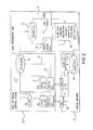
- FIG. 1 shows a control system with a data recording mechanism on a real machine plus a data preparation unit
- FIG. 2 shows a real or virtual control system on a virtual machine (with a machine model) plus a data preparation unit;
- FIG. 3 shows an adaption of a machine model for Boolean functions
- FIG. 4 shows a machine model for Boolean functions
- FIG. 5 shows a machine model generation unit
- FIG. 6 shows a basic algorithm of the cutter for Boolean functions for creating a machine model
- FIG. 7 shows the creation of a machine model for non-Boolean functions
- FIG. 8 shows tables with signal state changes in combination with the creation of the machine model according to FIG. 6 ;
- FIG. 9 shows a subsequent definition of individual signal curves for missing states and for modifying previously recorded signal curves
- FIG. 10 shows an adaption of a machine model for non-Boolean functions
- FIG. 11 shows a schematic depiction of the transfer of data that were ascertained into the machine model.
- FIG. 12 shows a schematic depiction of the checking of the machine model.
- FIG. 1 shows a preferred embodiment of inventive automation system 1 . It serves to create a new machine or system model, or to adapt an existing model.
- a real machine 2 is first connected to a real control system 3 .
- Real control system 3 is first connected with a data preparation unit 4 . Machine data may therefore be recorded.
- Real control system 3 includes an SPC 5 , and, optionally, an NC control 6 and, for at least a portion of time, a PC or sufficient memory 7 for long-term data recordings (data recording unit) 8 .
- SPC 5 , NC control 6 (as an alternative, a motion or robot control is used instead of an NC control), and the PC or memory 7 are connected with a common bus 10 .
- Bus 10 is preferably designed as a drive bus, which includes an interface 11 with real machine 2 .
- data recording unit 8 is connected with a field bus 12 . It is provided with an interface 13 , which is suitable for connecting I/O modules 14 of the real machine.
- SPC 5 of real control system 3 includes internal SPC data.
- NC control 6 which is available as an option, controls internal NC data, as is common with control systems of this type.
- PC 7 which is also available as an option—provides PC data to data recording unit 8 .
- data recording unit 8 is connected to data preparation unit 4 .
- Data preparation unit 4 includes a data memory 15 for storing previously recorded data, and a machine model generation unit 16 , and/or a machine model adaption unit 17 , and a machine model memory 18 .
- Data memory 15 contains a copy of the data that were recorded in data recording unit 8 of real control system 3 . These data undergo data analysis in machine model generation unit 16 using mathematical tools. Machine model 24 is therefore created in data analysis unit 16 .
- parameter identification may be carried out using machine model adaption unit 17 for existing machine models, i.e., only one parameter identification applies, instead of the function/parameter identification, since the function is already specified by the machine/component model.
- the required model data may be transferred as a complete machine model to the virtual machine when the data come from machine model generation 16 , or as a partial model when the data come from machine model adaption unit 17 , or when only individual parameters or data sequences have changed between the component/machine model transferred most recently to the virtual machine and the newly ascertained component/machine model.
- the machine model in machine model memory 18 stored in data preparation unit 4 may be composed of component functions with the associated parameters or, as an alternative, of stored recording sequences.
- data from a real machine may be recorded and analyzed under real environmental conditions. This recording takes place with real control system 3 , so that the recordings are very close to reality (and, in particular, they exist with an adequate accuracy of recording).
- FIG. 1 therefore shows a control system 1 with a data recording structure on a real machine 2 and data preparation unit 4 required therefor.
- Data recording unit 4 may also be located directly on the control PC or it may be realized on a server, which is reachable, e.g., via an Internet connection.
- FIG. 2 shows a real or virtual control system, which, in a subsequent step, is connected to a virtual machine with a machine model.
- Control system 1 may be a real control system 1 or a virtual control system 1 ′. They have the same structure as control system 1 shown in FIG. 1 .
- Control system 1 or 1 ′ is connected with a virtual machine 2 ′ via the real or a virtual drive bus 11 and the real or virtual field data bus 13 .
- the machine models of data recording unit 4 are made available to the virtual machine either in the form of individual component functions with the associated parameters, or as individual signal sequences. This forms the basis of a machine model 24 , as shown in FIG. 2 .
- Machine model 24 is processed cyclically in specified cycles in a solver 23 , which is connected with the real or virtual drive interface (or the virtual drive) 20 , or with the real or virtual field bus interface (or the virtual I/O modules) 21 .
- Virtual machine 2 ′ shown is provided to simulate behavior or dynamics and/or drives or processes.
- the inventive control system is provided with a data recording unit 8 for recording the machine data.
- System 1 includes a data preparation unit 4 for analyzing the data recorded in data recording unit 8 .
- the parameters of machine model 24 ascertained via data analysis are stored in virtual machine 2 ′, in order to simulate a machine behavior of a real machine 2 .
- measured values are first recorded under real application conditions on a real control system 1 .
- a real machine is therefore first connected to real control system 1 .
- the recorded data are then transferred to memory 15 of the data recording unit.
- the measured data need not be transferred manually. Instead, they may be transferred via drag & drog, import/export functions, or automatically once the measurement has ended, as shown in FIG. 1 . Complex measurements and evaluations may be eliminated as a result.
- the recorded data are made available to the virtual machine for processing in the solver using mathematical tools in the form of a machine model (individual component functions with the associated parameters or individual signal sequences).
- the transfer may take place (as described above) either as a complete machine model—when the data come from machine model generation 16 —to the virtual machine, or the transfer may take place as a partial model, when the data come from machine model adaption unit 17 .
- the real control system and the virtual control system may be tested with the virtual machine, which was obtained via the present invention.
- the virtual machine deviates only slightly from a real machine, since it automatically takes environmental influences—such as temperature fluctuations or the like—into account, and it simulates reactions to influences of this type.
- model data 24 from machine model memory 18 of data preparation unit 4 to the machine model memory of the virtual machine may take place via drag & drop, import/export functions, or in a fully automated manner (using a unique identifier for every individual component).
- FIG. 3 shows, as an example, an adaption of an existing machine model for Boolean functions using mathematical tools in machine model adaption unit 17 .
- Reference letter T represents the recording cycle, which particularly preferably also corresponds to that of the solver (player cycle) in the virtual machine.
- two input signals ES 1 and ES 2 are provided, for example; they are sent to a component 30 , e.g., a hydraulic pump.
- Signals ES 1 and ES 2 are Boolean signals with logical values 0 and 1.
- the component of hydraulic pump 30 delivers an output signal AS, also with Boolean values 0 and 1.
- FIG. 3 therefore illustrates that function values of elementary functions are used, the elementary functions being ⁇ t values of timer functions. Several ⁇ t values are therefore ascertained. The ⁇ t values are used to calculate a mean, so that a machine model may be formed that is as close to reality as possible.
- FIG. 4 shows an example of creating a machine model in machine model generation unit 16 for Boolean functions, also using the component “hydraulic pump” 30 .
- Two input signals ES 1 and ES 2 are present, and the signals may be time-shifted.
- the positive slopes of signals ES 1 and ES 2 are labeled t 1 and t 2 .
- Output signal AS is a signal with a positive slope at instant t 2 ′ and a negative slope at instant t 3 ′.
- signal ES 1 falls from logic 1 to logic 0.
- signal ES 2 increases from logic 0 to logic 1.
- Signal AS is characterized by the fact that two ⁇ t values are present, i.e., ⁇ t 2 t 2 ′ and ⁇ t 3 t 3 ′.
- the first value represents a time delay between the positive slope of second signal ES 2 and the positive slope of the output signal.
- the second value represents the time delay between the negative slope of first signal ES 1 and the negative slope of the output signal.
- the machine model is therefore based on two time-delay values.
- the operator may also modify the values entered by the model generation unit in the table.
- FIG. 5 shows one possible embodiment of machine model generation unit 16 .
- the recorded data are first read out of data memory 15 , the individual signal sequences are checked for repetition, then they are averaged and stored once more as an averaged recording.
- a cutter 28 runs via the optimized output signal sequences. If a “player” is included in the solver, the output signal sequences may be stored with the associated input signal combinations of a component directly as a component model (as part of the machine model). If the particular component is described with the aid of a mathematical function, the function and its parameters must also be ascertained.
- averaging may also take place in a different order. It would also be feasible for a cutter to initially ascertain output signal sequences, for them to then be averaged, and, finally, for the function/parameters to be identified.
- the averaging could also be the last unit, with the parameter values being averaged.
- Machine model adaption unit 17 has essentially the same design as that shown in FIG. 5 . Instead of the function/parameter identification, only parameter identification takes place, since the function is already specified by the machine/component model.
- Boolean functions of a component include, e.g., a time delay.
- Input signals ESi ⁇ i ⁇ (1, 2, 3, . . . ) ⁇ and output signals ASi ⁇ i ⁇ (1, 2, 3, . . . ) ⁇ are registered at the start instant.
- essential state changes of the output signals are registered as a function of the changes made to the input signals, and the associated time delay ⁇ t is incorporated, e.g., in a table (see FIG. 4 and FIG. 5 ).
- the associated Boolean functions may be easily ascertained in the function area of function/parameter identification of the data recording unit. Any time delay values that are present are also ascertained.
- the associated Boolean function including the delay time of the related component for the machine model—may be created.
- the state of the start instant is set at the end of the evaluation for missing (not recorded) combinations of output signals ASi.
- the operator defines “missing combinations” in this case as well.
- the operator also has the option of modifying existing records.
- the recorded data may be optimized by eliminating repetitive data.
- the associated functions e.g., the degree of a related polynomial function and the associated coefficients of the polynomial
- the recorded signal data as described above for Boolean functions, see FIG. 5 , if this is more favorable for processing (solver).
- FIG. 7 The creation of a machine model for components with non-Boolean functions (e.g., a hydraulic pump) is described in greater detail in FIG. 7 .
- the recorded data are read out of data memory 15 , checked for repetition, averaged, sent to a cutter (the basic algorithm is depicted in FIG. 6 ), and function/parameter identification is then carried out as an option.
- averaging may also take place in a different order. It would also be feasible for a cutter to initially ascertain output signal sequences, for them to then be averaged, and, finally, for the function/parameters to be identified.
- the averaging could also be the last unit, with the parameter values being averaged.
- FIG. 7 explains, as an example and with reference to FIG. 8 and FIG. 9 , the creation of the machine model and the algorithm for machine components with non-Boolean functions, e.g., a hydraulic pump.
- the cutter registers output signal AS as a function of input signals ES 1 and ES 2 , as shown in the tables ( FIG. 8 ).
- the state changes to first signal ES 1 are registered.
- State changes to second input signal ES 2 are registered in the lower table (shown as two tables, due to space limitations) in FIG. 8 .
- FIG. 7 illustrates another possibility for optimizing the data generated by the cutter.
- an optimizer of this type could be placed at the end of the cutter.
- identical data points in a recording sequence are crossed out, for example—they could be deleted without affecting the recording accuracy.
- a curve shape 26 may be defined using individual points (filling a cutter sequence) or curves, such as an exponential function. Delays ( ⁇ t values) may also be easily taken into account.
- the table shown in FIG. 9 is the same as the table shown in the middle of FIG. 8 .
- An existing machine model and/or an existing component model may also be adapted using non-Boolean functions, as shown in FIG. 10 .
- a digital signal ES 1 and a second digital signal ES 2 with several level values (1, 2, 3) are used. They may also be signals that are sent to a hydraulic pump.
- Output signal AS shown at the bottom of FIG. 10 , also has several level values (1 through 5).
- FIG. 11 shows, as an example, the incorporation of the data that were ascertained into the machine model of the virtual machine.
- the characteristics of the components in data preparation module 4 are shown at the left in FIG. 11 .
- Typical parameters are the execution times of auxiliary functions ( ⁇ t 1 , At 2 and At 3 ) or, e.g., the graph of a pump pressure in the form of a polynomial of the nth degree.
- a check of the virtual machine model may be carried out using a real machine, as shown in FIG. 12 .
- Data preparation unit 4 shown in FIG. 12 receives recorded data from the real machine and from the virtual machine that is used. The data are compared and optimized in order to optimize the machine model for every individual component. This may take place as described above by fitting the individual functions, including the associated coefficients, or by fitting the recorded output data sequences for the individual input combinations of the individual components.
- the recorded output signal sequences may be optimized by eliminating repetitive data. This applies, in particular, for signal values at the end of the recording (see FIG. 7 ).
- the associated input and output signals of the particular components are recorded on real control system 3 (real control system 3 being connected to the real machine), and the related data on the virtual component are recorded on the second (real or virtual) control system—the second control system being connected to a virtual machine—, and the recordings of the related components of the virtual machine are optimized, if necessary, and compared with the real machine, and the related component model is optimized based on the data comparison and is then made available in an optimized form to the virtual machine.
- real control system 3 being connected to the real machine
- the related data on the virtual component are recorded on the second (real or virtual) control system—the second control system being connected to a virtual machine—
- the recordings of the related components of the virtual machine are optimized, if necessary, and compared with the real machine, and the related component model is optimized based on the data comparison and is then made available in an optimized form to the virtual machine.
- machine models the component models of which are composed of functions with the associated parameters
- a machine model the component models of which are composed exclusively of output signal sequences/output values
- other machine models are also feasible, in which a portion of the components is described using functions and associated parameters, and the other portion of the components is described using output signal sequences/output values.
- the present invention is very well-suited for behaviorial simulation—also referred to as peripheral simulation—and for dynamic or process simulation of a machine/system. “Intelligent algorithms” may be used to ascertain the machine behavior in an automated manner.
- the present invention may be used not only on machines and components, e.g., a hydraulic pump, but also on complex systems, in which case more complex functions may be used rather than elementary functions such as timer functions.
- the present invention and the mechanisms described above for creating and adapting models for behavioral simulation may also be transferred to the area of dynamics simulation and process simulation.
Landscapes
- Physics & Mathematics (AREA)
- General Physics & Mathematics (AREA)
- Engineering & Computer Science (AREA)
- Automation & Control Theory (AREA)
- Testing And Monitoring For Control Systems (AREA)
- Feedback Control In General (AREA)
Applications Claiming Priority (3)
| Application Number | Priority Date | Filing Date | Title |
|---|---|---|---|
| DE102006059430 | 2006-12-15 | ||
| DE102006059430A DE102006059430A1 (de) | 2006-12-15 | 2006-12-15 | Automatisierte Erstellung und Adaption eines Maschinen- oder Anlagenmodells |
| DE102006059430.4 | 2006-12-15 |
Publications (2)
| Publication Number | Publication Date |
|---|---|
| US20080147209A1 US20080147209A1 (en) | 2008-06-19 |
| US8855792B2 true US8855792B2 (en) | 2014-10-07 |
Family
ID=39156440
Family Applications (1)
| Application Number | Title | Priority Date | Filing Date |
|---|---|---|---|
| US11/950,970 Expired - Fee Related US8855792B2 (en) | 2006-12-15 | 2007-12-05 | Automated creation and adaption of a machine or system model |
Country Status (3)
| Country | Link |
|---|---|
| US (1) | US8855792B2 (fr) |
| EP (1) | EP1933214B1 (fr) |
| DE (1) | DE102006059430A1 (fr) |
Cited By (3)
| Publication number | Priority date | Publication date | Assignee | Title |
|---|---|---|---|---|
| US20150376868A1 (en) * | 2014-06-27 | 2015-12-31 | Topcon Positioning Systems, Inc. | Method and Apparatus for Implementing Operational Practices for Construction Machines |
| US9941696B2 (en) | 2014-04-06 | 2018-04-10 | CleanSpark Technologies LLC | Establishing communication and power sharing links between components of a distributed energy system |
| US11079735B2 (en) | 2015-09-18 | 2021-08-03 | Siemens Aktiengesellschaft | Control system and method for operating a control system with real control and virtual control |
Families Citing this family (27)
| Publication number | Priority date | Publication date | Assignee | Title |
|---|---|---|---|---|
| US9565275B2 (en) | 2012-02-09 | 2017-02-07 | Rockwell Automation Technologies, Inc. | Transformation of industrial data into useful cloud information |
| US9459616B2 (en) * | 2007-08-03 | 2016-10-04 | Hurco Companies, Inc. | Universal conversational programming for machine tool systems |
| US8655461B2 (en) * | 2010-05-25 | 2014-02-18 | Siemens Product Lifecycle Management Software Inc. | Method, system, and non-transitory computer readable storage medium for generating code for a closed-loop controller |
| DE102011077318B4 (de) * | 2011-06-09 | 2015-07-16 | Siemens Aktiengesellschaft | Simulationssystem, Verfahren zur Durchführung einer Simulation, Leitsystem und Computerprogrammprodukt |
| DE102011077319B4 (de) * | 2011-06-09 | 2015-08-06 | Siemens Aktiengesellschaft | Simulationssystem, Verfahren zur Durchführung einer Simulation, Leitsystem und Computerprogrammprodukt |
| DE102011077317B4 (de) * | 2011-06-09 | 2015-10-01 | Siemens Aktiengesellschaft | Simulationssystem, Verfahren zur Durchführung einer Simulation, Leitsystem und Computerprogrammprodukt |
| US9477936B2 (en) | 2012-02-09 | 2016-10-25 | Rockwell Automation Technologies, Inc. | Cloud-based operator interface for industrial automation |
| EP2801872B1 (fr) * | 2013-05-06 | 2018-06-06 | dSPACE digital signal processing and control engineering GmbH | Dispositif de test pour le test d'un appareil de commande virtuel |
| US9786197B2 (en) | 2013-05-09 | 2017-10-10 | Rockwell Automation Technologies, Inc. | Using cloud-based data to facilitate enhancing performance in connection with an industrial automation system |
| US10026049B2 (en) | 2013-05-09 | 2018-07-17 | Rockwell Automation Technologies, Inc. | Risk assessment for industrial systems using big data |
| US9709978B2 (en) | 2013-05-09 | 2017-07-18 | Rockwell Automation Technologies, Inc. | Using cloud-based data for virtualization of an industrial automation environment with information overlays |
| US9438648B2 (en) | 2013-05-09 | 2016-09-06 | Rockwell Automation Technologies, Inc. | Industrial data analytics in a cloud platform |
| US9989958B2 (en) | 2013-05-09 | 2018-06-05 | Rockwell Automation Technologies, Inc. | Using cloud-based data for virtualization of an industrial automation environment |
| US9703902B2 (en) | 2013-05-09 | 2017-07-11 | Rockwell Automation Technologies, Inc. | Using cloud-based data for industrial simulation |
| US9646114B2 (en) * | 2013-07-10 | 2017-05-09 | The Boeing Company | Electrical power system stability |
| JP2018510424A (ja) * | 2015-03-12 | 2018-04-12 | トランスオーシャン セドコ フォレックス ベンチャーズ リミテッド | 慣性航行システムを用いた動的位置決め(dp)ドライブオフ(do)軽減 |
| US11513477B2 (en) | 2015-03-16 | 2022-11-29 | Rockwell Automation Technologies, Inc. | Cloud-based industrial controller |
| US11243505B2 (en) | 2015-03-16 | 2022-02-08 | Rockwell Automation Technologies, Inc. | Cloud-based analytics for industrial automation |
| US10496061B2 (en) * | 2015-03-16 | 2019-12-03 | Rockwell Automation Technologies, Inc. | Modeling of an industrial automation environment in the cloud |
| US11042131B2 (en) | 2015-03-16 | 2021-06-22 | Rockwell Automation Technologies, Inc. | Backup of an industrial automation plant in the cloud |
| EP3144751B1 (fr) * | 2015-09-18 | 2021-10-27 | Siemens Aktiengesellschaft | Système de commande et procédé de fonctionnement d'un système de commande doté d'une commande réelle et virtuelle destinée à la surveillance de processus |
| EP3144756A1 (fr) * | 2015-09-18 | 2017-03-22 | Siemens Aktiengesellschaft | Systeme de commande et procede de fonctionnement d'un systeme de commande dote d'une commande reelle et virtuelle destine a reduire les temps d'arret |
| DE102016103117A1 (de) | 2016-02-23 | 2017-08-24 | Krones Ag | Verfahren zum Betreiben einer Behandlungsanlage zum Behandeln von Behältnissen mit Rezepterstellung für die Steuerung |
| EP3537239A1 (fr) * | 2018-03-06 | 2019-09-11 | Siemens Aktiengesellschaft | Procédé d'utilisation d'une machine-outil au moyen de l'adaptation d'un modèle de données précompilé |
| CN109902069A (zh) * | 2019-03-04 | 2019-06-18 | 重庆科技学院 | 一种智能数学模型储存系统及方法 |
| AT522186B1 (de) * | 2019-05-20 | 2020-09-15 | Dipl Ing Dipl Ing Fh Markus Gruber | Computerimplementiertes Verfahren zur rechnergestützten Erzeugung eines ausführbaren Steuerungsprogramms zur Steuerung und/oder Regelung eines technischen Prozesses |
| CN112114533B (zh) * | 2020-08-26 | 2024-05-03 | 深圳奇迹智慧网络有限公司 | 物联网数据处理方法、装置、计算机设备和存储介质 |
Citations (24)
| Publication number | Priority date | Publication date | Assignee | Title |
|---|---|---|---|---|
| WO1993025953A1 (fr) | 1992-06-15 | 1993-12-23 | E.I. Du Pont De Nemours And Company | Systeme et procede pour la reconciliation amelioree des donnees en circulation |
| EP0875808A2 (fr) | 1997-04-30 | 1998-11-04 | Schenck Panel Production Systems GmbH | Système et méthode pour la modélisation de processus d'une installation technique |
| DE19841165A1 (de) | 1998-09-09 | 2000-03-16 | Abb Research Ltd | Verfahren zur Bestimmung eines Prozeßdatenvalidierungsmodells |
| US6209119B1 (en) * | 1997-04-10 | 2001-03-27 | Matsushita Electric Industrial Co., Ltd. | Apparatus and method for synthesizing module |
| US6556950B1 (en) * | 1999-09-30 | 2003-04-29 | Rockwell Automation Technologies, Inc. | Diagnostic method and apparatus for use with enterprise control |
| US20030139916A1 (en) * | 2002-01-18 | 2003-07-24 | Jonggeun Choe | Method for simulating subsea mudlift drilling and well control operations |
| US20030174147A1 (en) * | 2001-08-13 | 2003-09-18 | David Jaffe | Device, system and method for simulating a physical system |
| US20040006420A1 (en) * | 2002-02-22 | 2004-01-08 | Honda Giken Kogyo Kabushiki Kaisha | Control system for plant |
| US20040073475A1 (en) * | 2002-10-15 | 2004-04-15 | Tupper Joseph L. | Optimized parametric modeling system and method |
| US20040168680A1 (en) * | 2003-02-27 | 2004-09-02 | Honda Motor Co., Ltd. | Control apparatus for exhaust gas recirculation valve |
| US6853920B2 (en) | 2000-03-10 | 2005-02-08 | Smiths Detection-Pasadena, Inc. | Control for an industrial process using one or more multidimensional variables |
| US20050033466A1 (en) * | 2001-03-01 | 2005-02-10 | Evren Eryurek | Creation and display of indices within a process plant |
| US20050090929A1 (en) * | 2002-10-21 | 2005-04-28 | Siemens Aktiengesellschaft | Apparatus and method for simulation of the control and machine behavior of machine tools and production-line machines |
| US20050097194A1 (en) * | 1999-09-29 | 2005-05-05 | Fisher Controls International Llc | Downloadable code in a distributed process control system |
| US20050172218A1 (en) * | 1999-05-21 | 2005-08-04 | Sony Corporation | Information processing method and apparatus |
| US20050221514A1 (en) * | 2000-09-15 | 2005-10-06 | Advanced Micro Devices, Inc. | Adaptive sampling method for improved control in semiconductor manufacturing |
| US20060095853A1 (en) * | 2004-11-01 | 2006-05-04 | Elise Amyot | Event analysis system and method |
| US20060224534A1 (en) * | 1996-05-06 | 2006-10-05 | Hartman Eric J | Method and apparatus for training a system model with gain constraints using a non-linear programming optimizer |
| US20070061037A1 (en) * | 2005-09-12 | 2007-03-15 | Index-Werke Gmbh & Co. Kg Hahn & Tessky | Simulation system |
| US7209800B2 (en) * | 1997-09-09 | 2007-04-24 | Traub Drehmaschinen Gmbh | Process and system for generating or visualizing sets of control data |
| US20070192078A1 (en) * | 2006-02-14 | 2007-08-16 | Edsa Micro Corporation | Systems and methods for real-time system monitoring and predictive analysis |
| US20080289875A1 (en) * | 2004-09-03 | 2008-11-27 | The Robert Gordon University | Method and System for the Design of an Oil Well |
| US7480640B1 (en) * | 2003-12-16 | 2009-01-20 | Quantum Leap Research, Inc. | Automated method and system for generating models from data |
| US20090271012A1 (en) * | 2005-09-27 | 2009-10-29 | Markus Kopka | Method or System for Displaying an Internet Page on a Visualization Device of an Industrial Automation Device |
Family Cites Families (2)
| Publication number | Priority date | Publication date | Assignee | Title |
|---|---|---|---|---|
| DE10104163A1 (de) * | 2001-01-30 | 2002-08-14 | Rexroth Indramat Gmbh | Steuerungs-und/oder Überwachungsanlage von Maschinen und/oder Anlagen mit Aktionskomponenten unterschiedlicher Aktionsgruppen |
| US7187989B2 (en) * | 2003-12-22 | 2007-03-06 | Fakhruddin T Attarwala | Use of core process models in model predictive controller |
-
2006
- 2006-12-15 DE DE102006059430A patent/DE102006059430A1/de not_active Ceased
-
2007
- 2007-09-29 EP EP07019224.0A patent/EP1933214B1/fr not_active Not-in-force
- 2007-12-05 US US11/950,970 patent/US8855792B2/en not_active Expired - Fee Related
Patent Citations (28)
| Publication number | Priority date | Publication date | Assignee | Title |
|---|---|---|---|---|
| WO1993025953A1 (fr) | 1992-06-15 | 1993-12-23 | E.I. Du Pont De Nemours And Company | Systeme et procede pour la reconciliation amelioree des donnees en circulation |
| US20060224534A1 (en) * | 1996-05-06 | 2006-10-05 | Hartman Eric J | Method and apparatus for training a system model with gain constraints using a non-linear programming optimizer |
| US6209119B1 (en) * | 1997-04-10 | 2001-03-27 | Matsushita Electric Industrial Co., Ltd. | Apparatus and method for synthesizing module |
| US6212438B1 (en) | 1997-04-30 | 2001-04-03 | Schenk Panel Production Systems Gmbh | Method and apparatus for generating a model of an industrial production |
| EP0875808A2 (fr) | 1997-04-30 | 1998-11-04 | Schenck Panel Production Systems GmbH | Système et méthode pour la modélisation de processus d'une installation technique |
| US7209800B2 (en) * | 1997-09-09 | 2007-04-24 | Traub Drehmaschinen Gmbh | Process and system for generating or visualizing sets of control data |
| DE19841165A1 (de) | 1998-09-09 | 2000-03-16 | Abb Research Ltd | Verfahren zur Bestimmung eines Prozeßdatenvalidierungsmodells |
| US20050172218A1 (en) * | 1999-05-21 | 2005-08-04 | Sony Corporation | Information processing method and apparatus |
| US20050097194A1 (en) * | 1999-09-29 | 2005-05-05 | Fisher Controls International Llc | Downloadable code in a distributed process control system |
| US6556950B1 (en) * | 1999-09-30 | 2003-04-29 | Rockwell Automation Technologies, Inc. | Diagnostic method and apparatus for use with enterprise control |
| US6917845B2 (en) | 2000-03-10 | 2005-07-12 | Smiths Detection-Pasadena, Inc. | Method for monitoring environmental condition using a mathematical model |
| DE60113073T2 (de) | 2000-03-10 | 2006-08-31 | Smiths Detection Inc., Pasadena | Steuerung für einen industriellen prozes mit einer oder mehreren multidimensionalen variablen |
| US6853920B2 (en) | 2000-03-10 | 2005-02-08 | Smiths Detection-Pasadena, Inc. | Control for an industrial process using one or more multidimensional variables |
| US6865509B1 (en) | 2000-03-10 | 2005-03-08 | Smiths Detection - Pasadena, Inc. | System for providing control to an industrial process using one or more multidimensional variables |
| US20050221514A1 (en) * | 2000-09-15 | 2005-10-06 | Advanced Micro Devices, Inc. | Adaptive sampling method for improved control in semiconductor manufacturing |
| US20050033466A1 (en) * | 2001-03-01 | 2005-02-10 | Evren Eryurek | Creation and display of indices within a process plant |
| US20030174147A1 (en) * | 2001-08-13 | 2003-09-18 | David Jaffe | Device, system and method for simulating a physical system |
| US20030139916A1 (en) * | 2002-01-18 | 2003-07-24 | Jonggeun Choe | Method for simulating subsea mudlift drilling and well control operations |
| US20040006420A1 (en) * | 2002-02-22 | 2004-01-08 | Honda Giken Kogyo Kabushiki Kaisha | Control system for plant |
| US20040073475A1 (en) * | 2002-10-15 | 2004-04-15 | Tupper Joseph L. | Optimized parametric modeling system and method |
| US20050090929A1 (en) * | 2002-10-21 | 2005-04-28 | Siemens Aktiengesellschaft | Apparatus and method for simulation of the control and machine behavior of machine tools and production-line machines |
| US20040168680A1 (en) * | 2003-02-27 | 2004-09-02 | Honda Motor Co., Ltd. | Control apparatus for exhaust gas recirculation valve |
| US7480640B1 (en) * | 2003-12-16 | 2009-01-20 | Quantum Leap Research, Inc. | Automated method and system for generating models from data |
| US20080289875A1 (en) * | 2004-09-03 | 2008-11-27 | The Robert Gordon University | Method and System for the Design of an Oil Well |
| US20060095853A1 (en) * | 2004-11-01 | 2006-05-04 | Elise Amyot | Event analysis system and method |
| US20070061037A1 (en) * | 2005-09-12 | 2007-03-15 | Index-Werke Gmbh & Co. Kg Hahn & Tessky | Simulation system |
| US20090271012A1 (en) * | 2005-09-27 | 2009-10-29 | Markus Kopka | Method or System for Displaying an Internet Page on a Visualization Device of an Industrial Automation Device |
| US20070192078A1 (en) * | 2006-02-14 | 2007-08-16 | Edsa Micro Corporation | Systems and methods for real-time system monitoring and predictive analysis |
Non-Patent Citations (1)
| Title |
|---|
| Boros, Boolean regression, Annals of Operations Research, 1995. * |
Cited By (7)
| Publication number | Priority date | Publication date | Assignee | Title |
|---|---|---|---|---|
| US9941696B2 (en) | 2014-04-06 | 2018-04-10 | CleanSpark Technologies LLC | Establishing communication and power sharing links between components of a distributed energy system |
| US10658839B2 (en) | 2014-04-06 | 2020-05-19 | Cleanspark, Inc. | Establishing communication and power sharing links between components of a distributed energy system |
| US11581732B2 (en) | 2014-04-06 | 2023-02-14 | Fortress Power Llc | Establishing communication and power sharing links between components of a distributed energy system |
| US12170443B2 (en) | 2014-04-06 | 2024-12-17 | Fortress Power Llc | Establishing communication and power sharing links between components of a distributed energy system |
| US20150376868A1 (en) * | 2014-06-27 | 2015-12-31 | Topcon Positioning Systems, Inc. | Method and Apparatus for Implementing Operational Practices for Construction Machines |
| US9752303B2 (en) * | 2014-06-27 | 2017-09-05 | Topcon Positioning Systems, Inc. | Method and apparatus for implementing operational practices for construction machines |
| US11079735B2 (en) | 2015-09-18 | 2021-08-03 | Siemens Aktiengesellschaft | Control system and method for operating a control system with real control and virtual control |
Also Published As
| Publication number | Publication date |
|---|---|
| EP1933214B1 (fr) | 2018-06-06 |
| US20080147209A1 (en) | 2008-06-19 |
| DE102006059430A1 (de) | 2008-06-19 |
| EP1933214A2 (fr) | 2008-06-18 |
| EP1933214A3 (fr) | 2008-07-30 |
Similar Documents
| Publication | Publication Date | Title |
|---|---|---|
| US8855792B2 (en) | Automated creation and adaption of a machine or system model | |
| CN112506759B (zh) | 伺服系统控制软件的自动化测试方法、装置及存储介质 | |
| JP7402482B2 (ja) | 前段階コシミュレーション方法、デバイス、コンピュータ可読媒体、及びプログラム | |
| CN113821200B (zh) | 大数据任务可拖拽建模方法、系统、存储介质和终端 | |
| JP2002215423A (ja) | ソフトウェアモデル作成方法 | |
| CN108427383B (zh) | 工程设计装置、工程设计方法及存储介质 | |
| CN113632024A (zh) | 上级机器平台上的虚拟传感器 | |
| EP1510923A2 (fr) | Programme, dispositif et méthode de développement de programe pour l'estimation d'utilisation des ressources d'un micro-ordinateur | |
| CN121091816A (zh) | 一种模块化可重构产线控制系统集成方法 | |
| Stark et al. | Cloud-based integration of robot engineering data using AutomationML | |
| CN117350205A (zh) | 芯片的验证方法、装置、电子设备和存储介质 | |
| CN1989464A (zh) | 可编程控制器用程序生成装置、方法及程序存储介质 | |
| US20090150137A1 (en) | Method for generating performance evaluation model | |
| JP6649731B2 (ja) | Fpgaからリードバックするための信号の特定 | |
| CN111078444A (zh) | 用于故障行为的安全分析的系统和方法 | |
| CN117591550A (zh) | 基于语义标识变量与现场设备通信 | |
| CN110413468A (zh) | 基于代码突变的fpga在线故障注入方法 | |
| Lang et al. | Virtual powertrain calibration at GM becomes a reality | |
| JP7408815B2 (ja) | 機械学習データ生成装置、機械学習装置、機械学習モデルの生成方法及びプログラム | |
| JP2000200026A (ja) | プラント運転訓練用シミュレ―タ | |
| KR20180097128A (ko) | 가상 생산 시스템을 위한 가상 장비 등록 방법 및 장치 | |
| Talib et al. | Scenario-based Black Box Testing in COSMIC-FFP: a case study | |
| CN103518164A (zh) | 用于运行自动化系统的方法 | |
| TWI900033B (zh) | 基於元學習的熱變位自適應電腦數值控制補償系統及方法 | |
| CN120068465A (zh) | 测控设备的数字建模方法、装置及系统 |
Legal Events
| Date | Code | Title | Description |
|---|---|---|---|
| AS | Assignment |
Owner name: ROBERT BOSCH GMBH, GERMANY Free format text: ASSIGNMENT OF ASSIGNORS INTEREST;ASSIGNOR:LANDGRAF, GUENTHER;REEL/FRAME:020200/0479 Effective date: 20071121 |
|
| STCF | Information on status: patent grant |
Free format text: PATENTED CASE |
|
| MAFP | Maintenance fee payment |
Free format text: PAYMENT OF MAINTENANCE FEE, 4TH YEAR, LARGE ENTITY (ORIGINAL EVENT CODE: M1551) Year of fee payment: 4 |
|
| FEPP | Fee payment procedure |
Free format text: MAINTENANCE FEE REMINDER MAILED (ORIGINAL EVENT CODE: REM.); ENTITY STATUS OF PATENT OWNER: LARGE ENTITY |
|
| LAPS | Lapse for failure to pay maintenance fees |
Free format text: PATENT EXPIRED FOR FAILURE TO PAY MAINTENANCE FEES (ORIGINAL EVENT CODE: EXP.); ENTITY STATUS OF PATENT OWNER: LARGE ENTITY |
|
| STCH | Information on status: patent discontinuation |
Free format text: PATENT EXPIRED DUE TO NONPAYMENT OF MAINTENANCE FEES UNDER 37 CFR 1.362 |
|
| FP | Lapsed due to failure to pay maintenance fee |
Effective date: 20221007 |