US8857024B2 - Load leveling modification for front loading refuse truck - Google Patents
Load leveling modification for front loading refuse truck Download PDFInfo
- Publication number
- US8857024B2 US8857024B2 US13/563,382 US201213563382A US8857024B2 US 8857024 B2 US8857024 B2 US 8857024B2 US 201213563382 A US201213563382 A US 201213563382A US 8857024 B2 US8857024 B2 US 8857024B2
- Authority
- US
- United States
- Prior art keywords
- load
- slave cylinder
- collection body
- hydraulic
- lift
- Prior art date
- Legal status (The legal status is an assumption and is not a legal conclusion. Google has not performed a legal analysis and makes no representation as to the accuracy of the status listed.)
- Active, expires
Links
- 230000004048 modification Effects 0.000 title abstract description 8
- 238000012986 modification Methods 0.000 title abstract description 8
- 239000012530 fluid Substances 0.000 claims abstract description 15
- 238000005056 compaction Methods 0.000 claims description 6
- 238000003466 welding Methods 0.000 claims description 3
- 230000008878 coupling Effects 0.000 claims 5
- 238000010168 coupling process Methods 0.000 claims 5
- 238000005859 coupling reaction Methods 0.000 claims 5
- 238000000034 method Methods 0.000 claims 1
- 238000009434 installation Methods 0.000 description 3
- 238000006073 displacement reaction Methods 0.000 description 2
- 238000012423 maintenance Methods 0.000 description 2
- 230000004075 alteration Effects 0.000 description 1
- 238000011161 development Methods 0.000 description 1
- 230000018109 developmental process Effects 0.000 description 1
- 230000002028 premature Effects 0.000 description 1
- 230000003014 reinforcing effect Effects 0.000 description 1
- 230000000717 retained effect Effects 0.000 description 1
- 238000006467 substitution reaction Methods 0.000 description 1
Images


Classifications
-
- B—PERFORMING OPERATIONS; TRANSPORTING
- B65—CONVEYING; PACKING; STORING; HANDLING THIN OR FILAMENTARY MATERIAL
- B65F—GATHERING OR REMOVAL OF DOMESTIC OR LIKE REFUSE
- B65F3/00—Vehicles particularly adapted for collecting refuse
- B65F3/02—Vehicles particularly adapted for collecting refuse with means for discharging refuse receptacles thereinto
- B65F3/04—Linkages, pivoted arms, or pivoted carriers for raising and subsequently tipping receptacles
- B65F3/041—Pivoted arms or pivoted carriers
- B65F3/043—Pivoted arms or pivoted carriers with additional means for keeping the receptacle substantially vertical during raising
-
- B—PERFORMING OPERATIONS; TRANSPORTING
- B65—CONVEYING; PACKING; STORING; HANDLING THIN OR FILAMENTARY MATERIAL
- B65F—GATHERING OR REMOVAL OF DOMESTIC OR LIKE REFUSE
- B65F3/00—Vehicles particularly adapted for collecting refuse
- B65F3/02—Vehicles particularly adapted for collecting refuse with means for discharging refuse receptacles thereinto
- B65F2003/0263—Constructional features relating to discharging means
- B65F2003/0279—Constructional features relating to discharging means the discharging means mounted at the front of the vehicle
-
- Y—GENERAL TAGGING OF NEW TECHNOLOGICAL DEVELOPMENTS; GENERAL TAGGING OF CROSS-SECTIONAL TECHNOLOGIES SPANNING OVER SEVERAL SECTIONS OF THE IPC; TECHNICAL SUBJECTS COVERED BY FORMER USPC CROSS-REFERENCE ART COLLECTIONS [XRACs] AND DIGESTS
- Y10—TECHNICAL SUBJECTS COVERED BY FORMER USPC
- Y10T—TECHNICAL SUBJECTS COVERED BY FORMER US CLASSIFICATION
- Y10T29/00—Metal working
- Y10T29/49—Method of mechanical manufacture
- Y10T29/49716—Converting
Definitions
- front loading trucks which generally have a pair of forks attached to lift arms which raise a refuse container from the ground in front of the truck, over the truck cab, to a tipped position over the load opening of the refuse collection body.
- the load opening of a front loading refuse truck is located at the top of the collection body such that commodity in the refuse container will fall from the container into the load opening.
- Modern front loading trucks include hydraulic cylinders on the lift arms which can orient the forks of the arms and the operator then has manual control of the orientation of the lifted container by adjusting the extension of the rods on the hydraulic cylinders.
- the truck operator must activate a control to retract these cylinders when the container is at the dump position so that the container will tip sufficiently to empty into the load opening.
- leveling apparatus which operates through electronic means to maintain the lifted container in a generally upright orientation before it is located over the load opening.
- leveling the lifted container requires the truck operator to manually control the cylinders on the lift arms by operation of extra levers or other controls.
- An inexpensive modification is needed to retrofit existing front end loading refuse trucks to allow for automatic container leveling without operator intervention until the container is ready to be emptied.
- the present invention provides modification apparatus to convert an existing front loading refuse collection truck to provide an automatic leveling feature so that the lifted container remains level until the container is near the load opening of the refuse collection body of the truck.
- the apparatus operates by hydraulic fluid movement and requires no electronic controls or operator intervention to carry out proper container leveling.
- a slave cylinder mounted along a side of the collection truck body with one end joined to the body exterior and the other end connected to one of the lift arms can hydraulically control the orientation of the lifted container relative to the lift arms as the container is lifted.
- Use of the apparatus improves the performance of the front loading collection body by reducing the need for operator involvement to reduce the incidence of commodity prematurely falling from the container.
- This hydraulic load leveling apparatus avoids the costs associated with electronic control systems by eliminating the need for required electronic sensors and controllers and avoiding the costs associated with maintenance of such sensors and controllers in the harsh environment of a commodity collection truck.
- the apparatus can be retrofitted on an existing front loading collection body with little change to the body and various sizes and styles of front loading collection body can be modified with the same general apparatus.
- FIG. 1 is a side elevation of a front loading commodity collection body equipped with the present invention with a front intermediate container being lifted on the lift arms of the body.
- FIG. 2 is a close up perspective view of a part of the side of a commodity collection body which has been modified to receive retrofit apparatus to enable the body to automatically maintain the horizontal orientation of a container carried on the lift arms until the container is positioned for tipping over the load opening of the body.
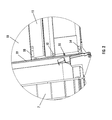
- FIG. 3 is a close up perspective view of the invention mounted to the refuse body to retrofit it for the load leveling feature.
- FIGS. 1-3 disclose a modification apparatus to be used to modify an existing front loading refuse collection truck so that the lifted container remains level until the container is near the load opening of the refuse collection body of the truck.
- the apparatus works entirely on hydraulic fluid movement and requires no extra controls to carry out proper load leveling.
- Addition of a multiposition mounting plate which mounts to one side of a conventional truck allows a slave cylinder to be added to a collection body to retrofit it with the leveling apparatus.
- FIG. 1 discloses a conventional front loading refuse body 10 which has been modified with the apparatus of the present invention.
- the refuse body 10 is equipped with lift arms 12 which rotate about pivots 14 on opposing sides of the body 10 .
- a pair of main hydraulic rams 16 on opposing sides of the body 10 raise and lower lift arms 12 .
- the lift arms 12 are coupled to a platform 18 on which an intermediate container 20 is carried.
- the platform 18 is hinged to the free ends 22 of the lift arms 12 by pivot axle 24 .
- the orientation of platform 18 and intermediate container 20 is controlled by load orienting cylinders 26 which are provided on lift arms 12 of the front loading refuse body 10 .
- Load orienting cylinders 26 include rods 28 which retract and extend from load orienting cylinders 26 to control the rotation of platform 18 about pivot axle 24 .
- the angle defined by platform 18 and lift arms 12 increases as the rods 28 extend.
- load orienting cylinders 26 are manually controlled by an operator controlling the extension or retraction of rods 28 .
- the current invention includes a slave cylinder 30 on one or the other side of the refuse body 10 , the slave cylinder 30 having a rod 32 hinged to the lift arms 12 near pivot 14 .
- the cylinder 30 is removably retained at its cap end 31 to a mounting plate 34 which is bolted or welded to refuse body 10 .
- the operator closes the hydraulic valve for the load orienting cylinders 26 , thereby placing the hydraulic lines from the slave cylinder 30 on the side of the collection body 10 in series with the load orienting cylinders 26 on the lift arms 12 .
- the rod 32 of the slave cylinder 30 retracts, fluid is expressed from the slave cylinder 30 and passed to the load orienting cylinders 26 causing their rods 28 to extend and to maintain a level orientation of the platform 18 on which the intermediate container 20 is carried.
- the truck operator adjusts the hydraulic control valve manually to bypass the hydraulic lines from the slave cylinder 30 and to cause the load orienting cylinders 26 to retract, thereby rotating the intermediate container 20 into a substantially tipped position so that commodity in the container 20 will fall into the load opening 15 of the collection body.
- the load orienting cylinders 26 retract.
- mounting plate 34 includes multiple mounting points 40 ( 40 a , 40 b . . . 40 h ) for mounting of slave cylinder 30 , the invention can easily be customized for a particular refuse collection body to be retrofitted with the invention.
- Retrofit brackets 50 , 52 , 54 have been welded to the side of body 10 along the junction 19 between compaction chamber 11 and storage compartment 7 . Retrofit brackets 50 , 52 and 54 are located above pivot mount 19 of the main lift arm cylinder 16 and are positioned to receive mounting plate 34 as seen in FIG. 3 . Hose clamp 55 may also be added. Therefore, it can be understood that the refuse body 10 in its original state need only be modified by the addition of retrofit brackets 50 , 52 , 54 to the exterior of compaction chamber 11 .
- mounting plate 34 is secured by bolts 56 to retrofit brackets 50 , 52 , 54 with a reinforcing plate 62 therebehind.
- Slave cylinder 30 has been securely connected at its cap end 31 to a selected one of mounting points 40 a , 40 b , 40 c , 40 d , 40 e , 40 f , 40 g , 40 h , selected to be appropriate to the travel of the lift arms 12 of the particular refuse body 10 being modified. Therefore mounting plate 34 may be used for a variety of front loading collection bodies. Hydraulic lines 64 , diagrammatically shown in FIG.
- Rod 32 retracts into slave cylinder 30 as lift arms 12 lift container 20 and, as seen in FIG. 1 , rod 32 is hinged to lift arm 12 at a connection tab 66 of lift arm 12 .
- Tab 66 may be required to be added to lift arm 12 during installation of the invention.
- Tab 66 is located between pivot 14 and ear 67 to which the rod of the main lift ram 16 is attached. This mounting for the rod 32 of slave cylinder 30 provides the proper proportional extension of rod 32 for the movement of lift arm 12 so that the slave cylinder 30 will properly control the extension of load orienting cylinders 26 .
- Mounting plate 34 is elongate and oriented generally vertically and attached to the side of refuse collection body 10 forward of the storage compartment 7 and above the pivot mount 19 of the collection body 10 .
- Mounting plate 34 includes openings for receiving bolts 56 therethrough to retain mounting plate 34 to retrofit brackets 50 , 52 , 54 .
- Mounting plate 34 includes a slightly concavely curved front edge 37 joined to a vertical upper front edge 39 , with mounting points 40 a , 40 b , 40 c , 40 d , 40 e , 40 f , 40 g , 40 h disposed along curved edge 37 .
- Voids 36 are cut into mounting plate 34 to reduce its weight.
- Mountings points 40 a , 40 b , 40 c , 40 d , 40 e , 40 f , 40 g , 40 h provide connections for attaching the cap end 31 of slave cylinder 30 .
- a selected mounting point 40 c is employed in the embodiment illustrated in FIG. 3 such that the mounting of cap end 31 of slave cylinder 30 thereto by bolt 68 through mounting point 40 c will allow proper spacing from the lift arm 12 to which the rod 32 of slave cylinder 30 will be attached.
- the mounting plate 34 and slave cylinder 30 can be fitted on a wide variety of sizes, makes and styles of front loading refuse body with only the addition of retrofit brackets 50 , 52 , 54 to the collection body to permit attachment of mounting plate 34 thereto.
- the apparatus of the current invention may be used to modify a front loading commodity collection body having only operator control of the orientation of a container carried on the lift arms 12 .
- the unmodified collection body 10 has a load leveling cylinder 26 mounted along each of the lift arms 12 .
- the modification steps include: welding at least two mounting brackets 50 , 54 , and preferably also a third bracket 52 to a first lateral side of the compaction chamber 11 near its junction 19 with the storage compartment 7 of the commodity collection body 10 , the brackets 50 , 52 , 54 having openings for receiving bolts 56 therein; bolting a mounting member 34 to the mounting brackets 50 , 52 , 54 by bolts 56 .
- the cap end 31 of the slave cylinder 30 is attached to a selected one of the plural connection points 40 a , 40 b , 40 c , 40 d , 40 e , 40 f , 40 g 40 h based on the quantity of hydraulic fluid needed to cause both load leveling cylinders 26 to extend a given distance in response to a fixed distance of travel of the rod 32 of the slave cylinder 30 .
- the rod 32 of the slave cylinder is attached to the tab by a hinge connection.
- first hydraulic connection 70 of the slave cylinder 30 is coupled to first hydraulic connection 70 of the slave cylinder 30 and the extend hydraulic port of each of the load leveling cylinders 26 .
- Second hydraulic connection 71 of the slave cylinder 30 is coupled to the retract hydraulic port of the each of the load leveling cylinders 26 .
- Hydraulic fluid from the slave cylinder 30 exits through first hydraulic connection 70 when the rod 32 thereof is urged into the slave cylinder 30 by lift arm 12 and a first hydraulic hose transmits the fluid to the extend hydraulic port of each load leveling cylinder 26 to cause both load leveling cylinders 26 to extend and increase the angle between the lift arms 12 and the platform 18 on which the container 20 is attached.
- Hydraulic fluid from the slave cylinder 30 exits through second hydraulic connection 71 of the slave cylinder 30 when the rod 32 thereof is pulled from the slave cylinder 30 by the lift arm 12 and a second hydraulic hose transmits the fluid to the retract hydraulic port of each load leveling cylinder 26 to cause both load leveling cylinders 26 to retract and decrease the angle between the lift arms 12 and the platform 18 .
- the attachment of the cap end 31 of the slave cylinder 30 to the selected mounting point 40 a , 40 b , 40 c , 40 d , 40 e , 40 f , 40 g , 40 h is determined by evaluating the quantity of displacement of hydraulic fluid per increment of extension distance of each load leveling cylinder 26 , doubling that quantity, and determining the concomitant displacement of hydraulic fluid per incremental retraction of the rod 32 of the slave cylinder, and then selecting the appropriate mounting point 40 a , 40 b , 40 c , 40 d , 40 e , 40 f , 40 g , 40 h to use to fasten the cap end 31 of the slave cylinder 30 . Experimentation may also be used to determine the proper mounting point 40 a , 40 b , 40 c , 40 d , 40 e , 40 f , 40 g , 40 h to be used.
- the invention may be easily added to various makes and models of front load refuse body to provide a leveling feature for a container carried on the lift arm 12 , whether it be an intermediate container 20 carried on a platform 18 or a conventional fork pocket equipped front loadable refuse container.
Landscapes
- Engineering & Computer Science (AREA)
- Mechanical Engineering (AREA)
- Refuse-Collection Vehicles (AREA)
- Load-Engaging Elements For Cranes (AREA)
Priority Applications (1)
| Application Number | Priority Date | Filing Date | Title |
|---|---|---|---|
| US13/563,382 US8857024B2 (en) | 2011-08-01 | 2012-07-31 | Load leveling modification for front loading refuse truck |
Applications Claiming Priority (2)
| Application Number | Priority Date | Filing Date | Title |
|---|---|---|---|
| US201161513831P | 2011-08-01 | 2011-08-01 | |
| US13/563,382 US8857024B2 (en) | 2011-08-01 | 2012-07-31 | Load leveling modification for front loading refuse truck |
Publications (2)
| Publication Number | Publication Date |
|---|---|
| US20130034412A1 US20130034412A1 (en) | 2013-02-07 |
| US8857024B2 true US8857024B2 (en) | 2014-10-14 |
Family
ID=47627038
Family Applications (1)
| Application Number | Title | Priority Date | Filing Date |
|---|---|---|---|
| US13/563,382 Active 2033-03-21 US8857024B2 (en) | 2011-08-01 | 2012-07-31 | Load leveling modification for front loading refuse truck |
Country Status (5)
| Country | Link |
|---|---|
| US (1) | US8857024B2 (fr) |
| AU (1) | AU2012290190A1 (fr) |
| CA (1) | CA2833336A1 (fr) |
| RU (1) | RU2014103962A (fr) |
| WO (1) | WO2013019808A2 (fr) |
Cited By (1)
| Publication number | Priority date | Publication date | Assignee | Title |
|---|---|---|---|---|
| US20130039728A1 (en) * | 2011-08-11 | 2013-02-14 | The Heil Co. | Refuse Collection Vehicle With Telescoping Arm |
Families Citing this family (2)
| Publication number | Priority date | Publication date | Assignee | Title |
|---|---|---|---|---|
| US9428334B2 (en) | 2013-05-17 | 2016-08-30 | The Heil Co. | Automatic control of a refuse front end loader |
| US20240076125A1 (en) * | 2022-09-07 | 2024-03-07 | Oshkosh Corporation | Alignment warning system for a refuse vehicle |
Citations (6)
| Publication number | Priority date | Publication date | Assignee | Title |
|---|---|---|---|---|
| US3827587A (en) * | 1969-07-31 | 1974-08-06 | Carrier Corp | Automatic self-leveling forks |
| US4085857A (en) | 1974-08-12 | 1978-04-25 | Sargent Industries, Inc. | Front end loader with improved apparatus for operating the lifting arms |
| US4091944A (en) | 1976-10-12 | 1978-05-30 | Leach Company | Front end loader refuse collection body |
| US4278390A (en) | 1979-09-04 | 1981-07-14 | Ahearn Thomas M | Garbage container truck |
| US4647267A (en) | 1985-05-06 | 1987-03-03 | Dempster Systems Inc. | Fork and arm mechanism for refuse container |
| US6152673A (en) * | 1995-03-07 | 2000-11-28 | Toccoa Metal Technologies, Inc. | Apparatus and method of automated fork repositioning |
-
2012
- 2012-07-31 AU AU2012290190A patent/AU2012290190A1/en not_active Abandoned
- 2012-07-31 CA CA2833336A patent/CA2833336A1/fr active Pending
- 2012-07-31 RU RU2014103962/13A patent/RU2014103962A/ru not_active Application Discontinuation
- 2012-07-31 US US13/563,382 patent/US8857024B2/en active Active
- 2012-07-31 WO PCT/US2012/049032 patent/WO2013019808A2/fr not_active Ceased
Patent Citations (6)
| Publication number | Priority date | Publication date | Assignee | Title |
|---|---|---|---|---|
| US3827587A (en) * | 1969-07-31 | 1974-08-06 | Carrier Corp | Automatic self-leveling forks |
| US4085857A (en) | 1974-08-12 | 1978-04-25 | Sargent Industries, Inc. | Front end loader with improved apparatus for operating the lifting arms |
| US4091944A (en) | 1976-10-12 | 1978-05-30 | Leach Company | Front end loader refuse collection body |
| US4278390A (en) | 1979-09-04 | 1981-07-14 | Ahearn Thomas M | Garbage container truck |
| US4647267A (en) | 1985-05-06 | 1987-03-03 | Dempster Systems Inc. | Fork and arm mechanism for refuse container |
| US6152673A (en) * | 1995-03-07 | 2000-11-28 | Toccoa Metal Technologies, Inc. | Apparatus and method of automated fork repositioning |
Non-Patent Citations (1)
| Title |
|---|
| International Search Report dated Jan. 28, 2013 from co-pending PCT application. |
Cited By (3)
| Publication number | Priority date | Publication date | Assignee | Title |
|---|---|---|---|---|
| US20130039728A1 (en) * | 2011-08-11 | 2013-02-14 | The Heil Co. | Refuse Collection Vehicle With Telescoping Arm |
| US10661986B2 (en) * | 2011-08-11 | 2020-05-26 | The Heil Co. | Refuse collection vehicle with telescoping arm |
| US11319148B2 (en) | 2011-08-11 | 2022-05-03 | The Heil Co. | Refuse collection vehicle with telescoping arm |
Also Published As
| Publication number | Publication date |
|---|---|
| WO2013019808A2 (fr) | 2013-02-07 |
| US20130034412A1 (en) | 2013-02-07 |
| WO2013019808A3 (fr) | 2013-03-28 |
| RU2014103962A (ru) | 2015-09-10 |
| CA2833336A1 (fr) | 2013-02-07 |
| AU2012290190A1 (en) | 2013-10-31 |
Similar Documents
| Publication | Publication Date | Title |
|---|---|---|
| US11319148B2 (en) | Refuse collection vehicle with telescoping arm | |
| US8708633B2 (en) | Container tilting apparatus and method | |
| EP1381551B1 (fr) | Bras de chargement automatique | |
| EP2113162A1 (fr) | Économie de grain, ensemble d'amorçage de décharge orientable | |
| US11401109B2 (en) | Refuse collection device | |
| US20150093221A1 (en) | Intermediate Container For A Front Loading Refuse Container | |
| US8857024B2 (en) | Load leveling modification for front loading refuse truck | |
| US4687407A (en) | Three-point hitch loader | |
| US20210308904A1 (en) | Concrete Transport Vehicle | |
| CN110040405A (zh) | 一种景观式垃圾压缩站 | |
| RU236399U1 (ru) | Узел навески устройства для разгрузки контейнеров | |
| CN107187896A (zh) | 一种粮仓粮食袋输送装置 | |
| CN217730504U (zh) | 一种便于装载车水平作业的调整机构 | |
| EP4417543A1 (fr) | Équipement pliable arrière de cabine pour soulever et manipuler des conteneurs de collecte de déchets | |
| CN106742981A (zh) | 一种垃圾车的自动提桶装置 | |
| US20140140798A1 (en) | Conveyor and hoist for air seeders | |
| BR102020005848A2 (pt) | Tubo de descarga e abastecimento mancalizado | |
| NZ620216B2 (en) | Refuse collection vehicle with telescoping arm | |
| EP2374658A1 (fr) | Dispositif de collecte d'ordures |
Legal Events
| Date | Code | Title | Description |
|---|---|---|---|
| AS | Assignment |
Owner name: KANN MANUFACTURING CORPORATION, IOWA Free format text: ASSIGNMENT OF ASSIGNORS INTEREST;ASSIGNORS:GOEDKEN, KENNETH D.;JOHNSON, MARLIN L.;ROWLAND, JARED L.;REEL/FRAME:028691/0880 Effective date: 20120719 |
|
| STCF | Information on status: patent grant |
Free format text: PATENTED CASE |
|
| MAFP | Maintenance fee payment |
Free format text: PAYMENT OF MAINTENANCE FEE, 4TH YR, SMALL ENTITY (ORIGINAL EVENT CODE: M2551) Year of fee payment: 4 |
|
| MAFP | Maintenance fee payment |
Free format text: PAYMENT OF MAINTENANCE FEE, 8TH YR, SMALL ENTITY (ORIGINAL EVENT CODE: M2552); ENTITY STATUS OF PATENT OWNER: SMALL ENTITY Year of fee payment: 8 |