US8865048B2 - Injection molding nozzle with dynamic seal - Google Patents
Injection molding nozzle with dynamic seal Download PDFInfo
- Publication number
- US8865048B2 US8865048B2 US13/730,775 US201213730775A US8865048B2 US 8865048 B2 US8865048 B2 US 8865048B2 US 201213730775 A US201213730775 A US 201213730775A US 8865048 B2 US8865048 B2 US 8865048B2
- Authority
- US
- United States
- Prior art keywords
- nozzle
- manifold
- bushing
- orifice
- Prior art date
- Legal status (The legal status is an assumption and is not a legal conclusion. Google has not performed a legal analysis and makes no representation as to the accuracy of the status listed.)
- Active, expires
Links
Images




Classifications
-
- B—PERFORMING OPERATIONS; TRANSPORTING
- B29—WORKING OF PLASTICS; WORKING OF SUBSTANCES IN A PLASTIC STATE IN GENERAL
- B29C—SHAPING OR JOINING OF PLASTICS; SHAPING OF MATERIAL IN A PLASTIC STATE, NOT OTHERWISE PROVIDED FOR; AFTER-TREATMENT OF THE SHAPED PRODUCTS, e.g. REPAIRING
- B29C45/00—Injection moulding, i.e. forcing the required volume of moulding material through a nozzle into a closed mould; Apparatus therefor
- B29C45/17—Component parts, details or accessories; Auxiliary operations
- B29C45/20—Injection nozzles
-
- B—PERFORMING OPERATIONS; TRANSPORTING
- B29—WORKING OF PLASTICS; WORKING OF SUBSTANCES IN A PLASTIC STATE IN GENERAL
- B29C—SHAPING OR JOINING OF PLASTICS; SHAPING OF MATERIAL IN A PLASTIC STATE, NOT OTHERWISE PROVIDED FOR; AFTER-TREATMENT OF THE SHAPED PRODUCTS, e.g. REPAIRING
- B29C45/00—Injection moulding, i.e. forcing the required volume of moulding material through a nozzle into a closed mould; Apparatus therefor
- B29C45/17—Component parts, details or accessories; Auxiliary operations
- B29C45/26—Moulds
- B29C45/27—Sprue channels ; Runner channels or runner nozzles
-
- B—PERFORMING OPERATIONS; TRANSPORTING
- B29—WORKING OF PLASTICS; WORKING OF SUBSTANCES IN A PLASTIC STATE IN GENERAL
- B29C—SHAPING OR JOINING OF PLASTICS; SHAPING OF MATERIAL IN A PLASTIC STATE, NOT OTHERWISE PROVIDED FOR; AFTER-TREATMENT OF THE SHAPED PRODUCTS, e.g. REPAIRING
- B29C45/00—Injection moulding, i.e. forcing the required volume of moulding material through a nozzle into a closed mould; Apparatus therefor
- B29C45/17—Component parts, details or accessories; Auxiliary operations
- B29C45/26—Moulds
- B29C45/27—Sprue channels ; Runner channels or runner nozzles
- B29C2045/2759—Nozzle centering or guiding means
-
- B—PERFORMING OPERATIONS; TRANSPORTING
- B29—WORKING OF PLASTICS; WORKING OF SUBSTANCES IN A PLASTIC STATE IN GENERAL
- B29C—SHAPING OR JOINING OF PLASTICS; SHAPING OF MATERIAL IN A PLASTIC STATE, NOT OTHERWISE PROVIDED FOR; AFTER-TREATMENT OF THE SHAPED PRODUCTS, e.g. REPAIRING
- B29C45/00—Injection moulding, i.e. forcing the required volume of moulding material through a nozzle into a closed mould; Apparatus therefor
- B29C45/17—Component parts, details or accessories; Auxiliary operations
- B29C45/26—Moulds
- B29C45/27—Sprue channels ; Runner channels or runner nozzles
- B29C2045/2762—Seals between nozzle and manifold
Definitions
- the present invention relates to nozzles for hot runner systems of plastic injection molds, and in particular, to such nozzles equipped with dynamic seals.
- Multi-cavity molds use manifolds to transfer molten plastic from a central feeding point, connected to the sprue bar of the injection machine, to a plurality of injection points leading to the molding cavities.
- a common problem of hot runner systems is the difficulty to control the thermal expansion of the manifold while maintaining effective sealing between nozzles and manifold.
- Typical challenges may be: excessive thermal expansion of the components, which may cause failure due to pressures, component fatigue, and wear; insufficient thermal expansion, which may cause uneven or minimal contact between mold components, resulting in plastic leaks; or, in the style of nozzles directly screwed into the manifold, excessive lateral expansion of the manifold, causing lateral deflection of the nozzles.
- An injection molding nozzle system includes a mold plate defining a first and a second pocket.
- a nozzle is provided in the second pocket, and defines a nozzle orifice extending in an axial direction to inject molten material into a mold from a downstream end of the nozzle orifice.
- a manifold is disposed in the first pocket, and defines a manifold orifice to supply the material to the nozzle orifice.
- a downstream end of the manifold orifice is in fluid communication with the upstream end of the nozzle orifice.
- a centering support ring is provided in the second pocket, to maintain the nozzle stationary with respect to the second pocket.
- a bushing extends between the first and second pockets, fixedly attached to the manifold and laterally movable with respect to the pockets and to the nozzle.
- the centers of the nozzle orifice and the manifold orifice are offset from one another in the lateral direction, a preload is defined between abutting surfaces of the nozzle and the bushing, an additional preload is defined between abutting surfaces of the manifold and the nozzle, and a gap is defined between the support ring and a shoulder at a downstream end of the second pocket.
- the manifold and the nozzle reach respective operating temperatures and thermally expand, such that the manifold moves laterally within the first pocket, and the nozzle remains substantially stationary within the second pocket.
- the centers of the nozzle orifice and the manifold orifice are thus aligned in the lateral direction, and the gap is closed by thermal expansion of the various components.
- the gap may be closed to a preload of approximately 0.001′′ to approximately 0.003′′.
- An additional gap may be defined between the support ring and the bushing at the ambient temperature.
- the system may further include dowels disposed between the nozzle and the manifold to prevent rotational movement of the nozzle with respect to the manifold.
- the bushing may include a flange abutting a downstream end of the manifold, and a collar defining an inner shoulder portion slidable within a notch of the nozzle.
- the system may further include a puck disposed between the manifold and the bushing.
- FIG. 1 is an exemplary vertical sectional view of an injection molding nozzle system typical of the prior art.
- FIG. 2 is an exemplary vertical sectional view of an injection molding nozzle system in accordance with a preferred embodiment of the invention.
- FIG. 3 is an exemplary vertical sectional view of the injection molding nozzle system of FIG. 2 , taken along line A-A of FIG. 2 .
- FIG. 4 is an exemplary horizontal sectional view taken along line B-B of FIG. 3 .
- FIG. 5 is an exemplary exploded perspective view of the injection molding system of FIG. 2 .
- FIG. 6 is an enlarged view of FIG. 2 .
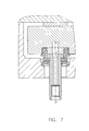
- FIG. 7 is an enlarged view of FIG. 3 , showing the injection molding nozzle at operating temperature, where axes X-X and Y-Y are in alignment.
- FIG. 7 a is an enlarged view of FIG. 3 , showing the injection molding nozzle in cold condition, where axes X-X and Y-Y are out of alignment.
- FIG. 8 is an exemplary vertical sectional view of an injection molding nozzle system in accordance with an alternative embodiment of the invention.
- FIG. 9 is an exemplary vertical sectional view of the injection molding nozzle system of FIG. 8 , taken along line A 1 -A 1 of FIG. 8 .
- FIG. 10 is an exemplary horizontal sectional view along line B 1 -B 1 of FIG. 9 .
- FIG. 11 is an exemplary exploded perspective view of the injection molding system of FIG. 8 .
- FIG. 12 is an enlarged view of FIG. 8 .
- FIG. 13 is an enlarged view of FIG. 9 .
- FIG. 1 which shows a typical prior art system
- a nozzle 2 , manifold 3 , and pressure pad 4 create a compression packet 5 between mold plates 6 and back plate 7 .
- Such systems are designed to have a cold gap between the nozzle 2 and the manifold 3 of typically 0.000′′ to 0.003′′ (inches), or as high as 0.012′′ in some cases.
- the term “cold gap,” as used herein, refers to the distance between the nozzle 2 and the manifold 3 at about room temperature.
- the typical nozzle/manifold assembly has an axial thermal expansion of 0.007′′-0.017′′ when heated to an operating temperature, usually around 400° F.-600° F. Consequently, substantial pressure forces are exerted on the manifold assembly steels and on to the mold plates and the fasteners securing them.
- a manifold 10 located in a pocket 12 of a mold plate 14 and backed by a pressure pad 11 secured to a back plate 15 (or to manifold 10 , securing means not shown), has an outlet hole 16 directing the flow of molten plastic to a nozzle 18 extending through a pocket 20 of mold plate 14 .
- the system is described herein with reference to one such nozzle; however, it should be understood that a plurality of nozzles may be in use with the manifold and mold plates, as necessitated by the scope of the application.
- a portion 22 of manifold 10 adjacent to nozzle 18 has an annular groove 22 a concentric with outlet hole 16 , the inner surface of this annular groove being a cylindrical centering surface 24 , while the outer surface of the annular groove has a threaded portion 26 .
- the system further comprises a bushing 28 and a centering support ring 30 .
- Bushing 28 has a protrusion 32 threadably connected to manifold 10 via thread 26 and centered about axis X-X of outlet hole 16 by the cylindrical surface 24 .
- the cylindrical surface 24 not only centers the bushing 28 , but also serves to protect thread 26 from seizing laterally, which might otherwise occur due to lateral movement of the manifold during operation.
- Bushing 28 further has a flange 34 and a collar 36 having an inner shoulder portion 38 .
- Outer surface of collar 36 is shaped to allow easy torquing (as necessary for installation of bushing 28 into manifold 10 via thread 26 ), having a pair or series of opposing flat surfaces, such as, for example, a hexagonal or an octagonal shape.
- Pocket 20 of mold plate 14 having axis Y-Y as shown in FIG. 6 , has a lead-in portion 40 , a centering cylindrical portion 42 , and a clearance portion 44 .
- the centering cylindrical portion 42 terminates at its bottom (in FIG. 6 ) end at a shoulder 42 a .
- Lead-in portion 40 may be of conical shape, or a combination of conical and cylindrical surfaces such as that shown in FIG. 6 , where the cylindrical lead-in portion is of larger diameter than the centering cylindrical portion 42 , in order to allow easy insertion of support ring 30 into the pocket. Cylindrical portion 42 thus centers support ring 30 about axis Y-Y of pocket 20 .
- An inner cylindrical portion 46 of support ring 30 concentric with cylindrical portion 42 , further centers nozzle 18 along axis Y-Y.
- bushing 28 and portion 22 of manifold 10 form a packet 48 centered about axis X-X of outlet hole 16
- nozzle 18 and support ring 30 form a packet 50 centered about axis Y-Y of pocket 20 of mold plate 14 .
- the system is designed with a preset lateral misalignment of axes X-X and Y-Y in cold (i.e. room temperature) condition (shown exaggerated for clarity in FIG. 7 a , which is seen from the direction perpendicular to FIG. 6 ), the two axes aligning as the system reaches operating temperature.
- the nozzle system of FIG. 6 has a preload at interfaces 52 (between manifold 10 and nozzle 18 ) and 54 (between shoulder of nozzle 18 and inner shoulder of bushing 28 ), and a cold gap at interfaces 56 (between bushing 28 and support ring 30 ) and 58 (between support ring 30 and shoulder 42 a ).
- the size of the cold gap varies with the application, being dependent on the thermal growth of the manifold thickness, such that the gap is reduced to zero at operating temperature.
- the system may have a preload of 0.001′′ to 0.003′′ when fully heated.
- the preload pressure at interfaces 52 and 54 creates a mechanical seal, preventing plastic leaks even if the injection process were to start prematurely, before reaching full operating temperature. Even if plastic were to leak at interface 52 , the mechanical seals at interfaces 54 and 64 would prevent it from reaching the mold plate pocket, which is a common problem of conventional systems, where plastic leaks may fill up the mold plate pockets, damaging nozzle heaters and causing extensive downtime, resulting in costly repairs.
- the nozzle system disclosed herein provides a pre-set, fully controlled pre-loaded system.
- Prior art systems start anywhere from zero to 0.003′′ gap at ambient temperature, while at operating temperatures the system could load to 0.017′′ and higher, putting considerable compression strain on the mold steels.
- the system disclosed herein allows the pre-loads to be set mechanically at ambient temperature, and maintains those pre-loads at operating temperatures. The loads caused by thermal expansion of mold components are now prevented from being transferred to the mold steels.
- collar 36 , inner shoulder portion 38 , and flange 34 in effect becomes a high-tension spring, holding constant tension on the nozzle against the manifold, thus applying the appropriate preloads mechanically (i.e. without the need to bring the system to operating temperature).
- the size of the gap at interface 64 is tightly toleranced, chosen to achieve the adequate amount of mechanical preload at interfaces 52 and 54 in cold condition.
- protrusion 32 of bushing 28 is not in contact with the manifold at the top of the groove 22 a ; there is a small gap between these elements (somewhat visible in FIG. 6 ).
- the flange 34 abutting the manifold 10 at 64 , and not the protrusion 32 abutting the manifold, limits how far the bushing 28 can be threaded into the annular groove 22 a.
- the mechanical preloads of the system described herein allow cold start-ups without danger of leaks.
- a drawback of conventional systems is that they rely on axial thermal expansion of components to achieve sealing against plastic leaks. If the injection process is started before reaching full operating temperature, the system is likely to leak as the cold gaps are not fully closed.
- the system described herein eliminates this problem by having mechanical preloads pre-set in cold condition, as explained above.
- a further advantage is extended life.
- a typical nozzle/manifold assembly can have a thermal axial expansion as high as 0.017′′ when heated to operating temperature. This results in high compressive loads on the steels of the mold plates and manifold, the manifold being susceptible to hobbing between nozzles and pressure pads, sometimes leading to indentations so large they are visible with the naked eye.
- Such wear shows that prior art systems have a greater chance of leakage as time progresses.
- the current system with a zero gap or a preload of 0.001′′ to 0.003′′ when fully heated, will have a considerably longer life than conventional systems.
- the preloaded seal at interface 64 via flange 34 the preload force being calculated such that it retains nozzle 18 in place and seals it, but all along allowing the manifold to expand laterally so that axes X-X and Y-Y become aligned at operating temperature.
- the dimension of the cylindrical centering surface 24 compared to the inner diameter of protrusion 32 is such that when there is lateral movement of the manifold, it doesn't subject thread 26 to extreme forces, preventing lateral seizing of the threads.
- the combination of all dimensional tolerances and cold gaps allows the system to have growth of only 0.001′′ to 0.003′′ subjected on the manifold and mold plates, thus eliminating excessive hobbing on manifold. As mentioned above, cold start-up leakage and heater failure leakage are prevented.
- a further advantage of the present design is that it allows shipment of pre-assembled hot runner systems to customers, and easy on-site installation into molds.
- the nozzles can be provided with pre-installed and pre-wired heaters, and with nozzle tips suited to the specific application.
- a further feature of this system allows for easy nozzle tip change without removal of the nozzle from the hot runner system.
- a pair of dowels 60 fixedly attached to manifold 10 in the embodiment shown, project into clearance pockets 62 of nozzle 18 .
- Pockets 62 are shaped to allow the relative motion caused by thermal expansion of the manifold relative to the nozzles as explained above (in the direction perpendicular to the page in FIG. 6 , left and right in FIGS. 7 and 7 a ), but preventing nozzle 18 from rotating about axis Y-Y as the nozzle tip (not shown) is threadably disengaged or re-engaged into front end 68 of the nozzle, to deliver the flow of molten plastic into the molding cavity.
- nozzle tips may be used with the nozzle system described above, such as those disclosed in applicant's U.S. Pat. Nos. 7,207,795; 7,329,117; and 7,413,431, all of which are incorporated by reference herein.
- dowels 60 may alternatively be fixedly secured to nozzle 18 , and pockets 62 may be accordingly provided in portion 22 of manifold 10 .
- This embodiment additionally includes a puck 128 centered into a manifold 110 by a cylindrical surface 124 (concentric with a manifold outlet hole 116 having an axis X 1 -X 1 ) and secured to manifold 110 by way of a thread 126 .
- Puck 128 extends beyond the face of manifold 110 , its protrusion having an outer thread 127 .
- a collar bushing 136 having an inner shoulder portion 138 , is threadably secured to puck 128 via thread 127 until collar bushing 136 is torqued firmly against manifold 110 at interface 164 according to proper torquing methods.
- a nozzle 118 and a centering support ring 130 (similar to those shown in the first embodiment) complete the nozzle assembly.
- Support ring 130 is centered along axis Y 1 -Y 1 of mold plate pocket 120 by a cylindrical centering portion 142 of the mold plate pocket.
- Nozzle 118 is in turn centered along axis Y 1 -Y 1 via an inner cylindrical surface 146 of support ring 130 .
- This system has a preload at interfaces 152 (between puck 128 and nozzle 118 ) and 154 (between shoulder of nozzle 118 and inner shoulder portion 138 of collar bushing 136 ), and a cold gap at interfaces 156 (between puck 128 and centering support ring 130 ) and 158 (between centering support ring 130 and the bottom of the mold plate pocket).
- puck 128 and collar bushing 136 together with portion 122 of manifold 110 adjacent the nozzle, form a packet 148 centered about axis X 1 -X 1 of outlet hole 116 , while nozzle 118 and support ring 130 form a packet 150 , centered about axis Y 1 -Y 1 of pocket 120 of mold plate 114 .
- axes X 1 -X 1 and Y 1 -Y 1 align, while the thermal expansion of the components achieves axial preload, effectively sealing against plastic leaks (puck 128 being outfitted with a seal ring 170 behind the thread, as an added measure).
- this system is similar to the previous embodiment, and will therefore not be described in more detail.
- nozzles threaded into the manifold must have a minimum length in order to allow axial deflection without snapping, minimum lengths usually being around 5.5′′-6.0′′.
- the present design allowing relative motion between packets 48 and 50 (or 148 and 150 ) as explained above, prevents the lateral thermal expansion of the manifold from deflecting the nozzle axis, thus posing no limitations on the shortness of nozzles allowed, therefore resulting in more compact stack sizes.
Landscapes
- Engineering & Computer Science (AREA)
- Manufacturing & Machinery (AREA)
- Mechanical Engineering (AREA)
- Moulds For Moulding Plastics Or The Like (AREA)
- Injection Moulding Of Plastics Or The Like (AREA)
Priority Applications (2)
| Application Number | Priority Date | Filing Date | Title |
|---|---|---|---|
| US13/730,775 US8865048B2 (en) | 2012-12-28 | 2012-12-28 | Injection molding nozzle with dynamic seal |
| CA2837637A CA2837637C (fr) | 2012-12-28 | 2013-12-17 | Buse de moulage par injection a joint d'etancheite dynamique |
Applications Claiming Priority (1)
| Application Number | Priority Date | Filing Date | Title |
|---|---|---|---|
| US13/730,775 US8865048B2 (en) | 2012-12-28 | 2012-12-28 | Injection molding nozzle with dynamic seal |
Publications (2)
| Publication Number | Publication Date |
|---|---|
| US20140183790A1 US20140183790A1 (en) | 2014-07-03 |
| US8865048B2 true US8865048B2 (en) | 2014-10-21 |
Family
ID=51016279
Family Applications (1)
| Application Number | Title | Priority Date | Filing Date |
|---|---|---|---|
| US13/730,775 Active 2033-04-22 US8865048B2 (en) | 2012-12-28 | 2012-12-28 | Injection molding nozzle with dynamic seal |
Country Status (2)
| Country | Link |
|---|---|
| US (1) | US8865048B2 (fr) |
| CA (1) | CA2837637C (fr) |
Cited By (1)
| Publication number | Priority date | Publication date | Assignee | Title |
|---|---|---|---|---|
| US20230052671A1 (en) * | 2021-08-11 | 2023-02-16 | Hoffman Enclosures Inc. | Liquid Manifold for Electronics Cabinet |
Families Citing this family (3)
| Publication number | Priority date | Publication date | Assignee | Title |
|---|---|---|---|---|
| CN109049540A (zh) * | 2018-08-22 | 2018-12-21 | 珠海格力精密模具有限公司 | 注塑模具 |
| US11225003B2 (en) * | 2019-04-17 | 2022-01-18 | Mold-Masters (2007) Limited | Hot runner system |
| US12151414B2 (en) | 2021-07-22 | 2024-11-26 | Injectnotech Inc. | Injection molding system with dynamic nozzle seal |
Citations (5)
| Publication number | Priority date | Publication date | Assignee | Title |
|---|---|---|---|---|
| US5896640A (en) * | 1996-11-12 | 1999-04-27 | Husky Injection Molding Systems Ltd. | Deflection sealing apparatus and method |
| US6062846A (en) * | 1997-06-13 | 2000-05-16 | Husky Injection Molding Systems, Ltd. | Injection molding nozzle assembly |
| US6860732B2 (en) * | 2002-02-04 | 2005-03-01 | Mold-Masters Limited | Thermal seal between manifold and nozzle |
| US20120251657A1 (en) * | 2011-03-31 | 2012-10-04 | James Oliver Adas | Apparatus for Injection Molding |
| US20130056562A1 (en) * | 2010-02-01 | 2013-03-07 | Husky Injection Molding Systems Ltd. | Side Gate Nozzle Assembly |
-
2012
- 2012-12-28 US US13/730,775 patent/US8865048B2/en active Active
-
2013
- 2013-12-17 CA CA2837637A patent/CA2837637C/fr active Active
Patent Citations (5)
| Publication number | Priority date | Publication date | Assignee | Title |
|---|---|---|---|---|
| US5896640A (en) * | 1996-11-12 | 1999-04-27 | Husky Injection Molding Systems Ltd. | Deflection sealing apparatus and method |
| US6062846A (en) * | 1997-06-13 | 2000-05-16 | Husky Injection Molding Systems, Ltd. | Injection molding nozzle assembly |
| US6860732B2 (en) * | 2002-02-04 | 2005-03-01 | Mold-Masters Limited | Thermal seal between manifold and nozzle |
| US20130056562A1 (en) * | 2010-02-01 | 2013-03-07 | Husky Injection Molding Systems Ltd. | Side Gate Nozzle Assembly |
| US20120251657A1 (en) * | 2011-03-31 | 2012-10-04 | James Oliver Adas | Apparatus for Injection Molding |
Cited By (2)
| Publication number | Priority date | Publication date | Assignee | Title |
|---|---|---|---|---|
| US20230052671A1 (en) * | 2021-08-11 | 2023-02-16 | Hoffman Enclosures Inc. | Liquid Manifold for Electronics Cabinet |
| US12031780B2 (en) * | 2021-08-11 | 2024-07-09 | Hoffman Enclosures Inc. | Liquid manifold for electronics cabinet |
Also Published As
| Publication number | Publication date |
|---|---|
| US20140183790A1 (en) | 2014-07-03 |
| CA2837637C (fr) | 2020-08-18 |
| CA2837637A1 (fr) | 2014-06-28 |
Similar Documents
| Publication | Publication Date | Title |
|---|---|---|
| US6860732B2 (en) | Thermal seal between manifold and nozzle | |
| US20090194910A1 (en) | Two Stage Spring Pack Device for Hot Runner Sealing | |
| US8939756B2 (en) | Mold-tool system having a manifold extension and biasing assembly | |
| CA2837637C (fr) | Buse de moulage par injection a joint d'etancheite dynamique | |
| CN101318368A (zh) | 用于注射模制系统的歧管喷嘴连接 | |
| US5896640A (en) | Deflection sealing apparatus and method | |
| US9272453B1 (en) | Hot runner with removable gate pad | |
| CA2591729A1 (fr) | Robinet d'arret de cavite distincte pour moule a injection | |
| EP2214883A1 (fr) | Canal chauffé présentant une coulure de tige de soupape réduite | |
| US6368542B1 (en) | Thermal expansion compensation support | |
| US8899965B2 (en) | Mold arrangement having a melt distribution manifold with a hinged joint | |
| WO2010099602A1 (fr) | Elément d'étanchéité de coin de buse de moulage par injection | |
| US20050233028A1 (en) | Injection molding valve gate system and activating mechanism | |
| US8287272B1 (en) | Injection molding apparatus having a nozzle retaining clip | |
| US20090280209A1 (en) | Injection moulding device comprising needle valve nozzles in a back-to-back arrangement | |
| US12151414B2 (en) | Injection molding system with dynamic nozzle seal | |
| CA2672242C (fr) | Buse pour moulage par injection | |
| US11225003B2 (en) | Hot runner system | |
| US7658607B2 (en) | Cross-over nozzle system for stack molds | |
| US7258541B2 (en) | Thermal expansion compensation support | |
| US8128397B2 (en) | Cross-over nozzle system for stack molds | |
| EP3113924B1 (fr) | Retenue de buse pour système de collecteur | |
| US20070172538A1 (en) | Apparatus for injection molding |
Legal Events
| Date | Code | Title | Description |
|---|---|---|---|
| AS | Assignment |
Owner name: INJECTNOTECH INC., CANADA Free format text: ASSIGNMENT OF ASSIGNORS INTEREST;ASSIGNOR:CICCONE, VINCE;REEL/FRAME:030127/0528 Effective date: 20130313 |
|
| STCF | Information on status: patent grant |
Free format text: PATENTED CASE |
|
| MAFP | Maintenance fee payment |
Free format text: PAYMENT OF MAINTENANCE FEE, 4TH YR, SMALL ENTITY (ORIGINAL EVENT CODE: M2551) Year of fee payment: 4 |
|
| MAFP | Maintenance fee payment |
Free format text: PAYMENT OF MAINTENANCE FEE, 8TH YR, SMALL ENTITY (ORIGINAL EVENT CODE: M2552); ENTITY STATUS OF PATENT OWNER: SMALL ENTITY Year of fee payment: 8 |
|
| MAFP | Maintenance fee payment |
Free format text: PAYMENT OF MAINTENANCE FEE, 12TH YR, SMALL ENTITY (ORIGINAL EVENT CODE: M2553); ENTITY STATUS OF PATENT OWNER: SMALL ENTITY Year of fee payment: 12 |