US8902807B2 - Relay system based on resource allocation - Google Patents
Relay system based on resource allocation Download PDFInfo
- Publication number
- US8902807B2 US8902807B2 US13/201,121 US201013201121A US8902807B2 US 8902807 B2 US8902807 B2 US 8902807B2 US 201013201121 A US201013201121 A US 201013201121A US 8902807 B2 US8902807 B2 US 8902807B2
- Authority
- US
- United States
- Prior art keywords
- wireless resource
- relay
- data
- base station
- terminal
- Prior art date
- Legal status (The legal status is an assumption and is not a legal conclusion. Google has not performed a legal analysis and makes no representation as to the accuracy of the status listed.)
- Active, expires
Links
Images


Classifications
-
- H—ELECTRICITY
- H04—ELECTRIC COMMUNICATION TECHNIQUE
- H04B—TRANSMISSION
- H04B7/00—Radio transmission systems, i.e. using radiation field
- H04B7/14—Relay systems
- H04B7/15—Active relay systems
- H04B7/155—Ground-based stations
- H04B7/15528—Control of operation parameters of a relay station to exploit the physical medium
- H04B7/15542—Selecting at relay station its transmit and receive resources
-
- H—ELECTRICITY
- H04—ELECTRIC COMMUNICATION TECHNIQUE
- H04L—TRANSMISSION OF DIGITAL INFORMATION, e.g. TELEGRAPHIC COMMUNICATION
- H04L5/00—Arrangements affording multiple use of the transmission path
- H04L5/0001—Arrangements for dividing the transmission path
- H04L5/0003—Two-dimensional division
- H04L5/0005—Time-frequency
- H04L5/0007—Time-frequency the frequencies being orthogonal, e.g. OFDM(A) or DMT
- H04L5/001—Time-frequency the frequencies being orthogonal, e.g. OFDM(A) or DMT the frequencies being arranged in component carriers
-
- H—ELECTRICITY
- H04—ELECTRIC COMMUNICATION TECHNIQUE
- H04W—WIRELESS COMMUNICATION NETWORKS
- H04W72/00—Local resource management
- H04W72/04—Wireless resource allocation
- H04W72/044—Wireless resource allocation based on the type of the allocated resource
-
- H—ELECTRICITY
- H04—ELECTRIC COMMUNICATION TECHNIQUE
- H04W—WIRELESS COMMUNICATION NETWORKS
- H04W72/00—Local resource management
- H04W72/04—Wireless resource allocation
- H04W72/044—Wireless resource allocation based on the type of the allocated resource
- H04W72/0446—Resources in time domain, e.g. slots or frames
-
- H—ELECTRICITY
- H04—ELECTRIC COMMUNICATION TECHNIQUE
- H04W—WIRELESS COMMUNICATION NETWORKS
- H04W72/00—Local resource management
- H04W72/04—Wireless resource allocation
- H04W72/044—Wireless resource allocation based on the type of the allocated resource
- H04W72/0453—Resources in frequency domain, e.g. a carrier in FDMA
-
- H04W72/0493—
-
- H—ELECTRICITY
- H04—ELECTRIC COMMUNICATION TECHNIQUE
- H04W—WIRELESS COMMUNICATION NETWORKS
- H04W72/00—Local resource management
- H04W72/20—Control channels or signalling for resource management
-
- H—ELECTRICITY
- H04—ELECTRIC COMMUNICATION TECHNIQUE
- H04W—WIRELESS COMMUNICATION NETWORKS
- H04W72/00—Local resource management
- H04W72/50—Allocation or scheduling criteria for wireless resources
- H04W72/53—Allocation or scheduling criteria for wireless resources based on regulatory allocation policies
-
- H—ELECTRICITY
- H04—ELECTRIC COMMUNICATION TECHNIQUE
- H04W—WIRELESS COMMUNICATION NETWORKS
- H04W84/00—Network topologies
- H04W84/02—Hierarchically pre-organised networks, e.g. paging networks, cellular networks, WLAN [Wireless Local Area Network] or WLL [Wireless Local Loop]
- H04W84/04—Large scale networks; Deep hierarchical networks
- H04W84/042—Public Land Mobile systems, e.g. cellular systems
- H04W84/047—Public Land Mobile systems, e.g. cellular systems using dedicated repeater stations
-
- H—ELECTRICITY
- H04—ELECTRIC COMMUNICATION TECHNIQUE
- H04W—WIRELESS COMMUNICATION NETWORKS
- H04W88/00—Devices specially adapted for wireless communication networks, e.g. terminals, base stations or access point devices
- H04W88/02—Terminal devices
- H04W88/04—Terminal devices adapted for relaying to or from another terminal or user
Definitions
- the present invention relates to a mobile communication, and more particularly, to a communication system which transmits data using a relay.
- FIG. 1 illustrates a view showing links in a data transmission system using relays.
- the data transmission system includes a base station 110 , relays 120 and 150 , a macro terminal 130 , and a relay terminal 140 .
- the macro terminal transmits or receives data to or from the base station 110 through direct connection with the base station 110 .
- the relay terminal directly connects with the relay 120 .
- the relay terminal 140 transmits data to the relay 120 .
- the relay 120 forwards the received data to the base station 110 .
- the base station 110 transmits the data to the relay 120 and, accordingly, the relay 120 transmits the received data to the relay terminal 140 .
- the base station 110 , the relays 120 and 150 , and the terminals 130 and 140 may transmit and receive data using a wireless resource.
- a wireless resource e.g., a frequency range, a time slot, and the like may be used as the wireless resource.
- the data transmission system properly allocates the wireless resources to uplinks and downlinks between the base station 110 and the relay 120 , uplinks and downlinks between the relay 120 and the relay terminal 140 , and uplinks and downlinks between the base station 110 and the macro terminal 130 .
- the data transmission system transmits data using the allocated wireless resources.
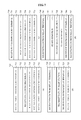
- FIG. 2 illustrates a drawing showing the structure of a data frame in a case where data transmission is performed by dividing frequency resources.
- Part (a) of FIG. 2 shows the structure of the data frame that a base station transmits to a relay.
- the data frame 210 may include a control signal region 211 , and data regions 212 , 213 , and 214 .
- a horizontal axis of the data frame denotes elapse of time while a vertical axis denotes a frequency range.
- the control signal region 211 may transmit control signals corresponding to a reference signal (RS), a physical control format indicator channel (PCFICH), a physical downlink control channel (PDCCH), and a Physical H-ARQ Indicator Channel (PHICH).
- RS reference signal
- PCFICH physical control format indicator channel
- PDCCH physical downlink control channel
- PHICH Physical H-ARQ Indicator Channel
- the control signal region 211 may include information on the data regions or wireless resources corresponding to the data regions.
- the control signal region 211 may include information on a starting point and an ending point of each region, and information on a transmission frequency range of each region.
- the data regions 212 , 213 , and 214 may include data regions 212 and 213 in which data is transmitted to a plurality of relays and a data region 214 in which data is transmitted to a macro terminal.
- transmission of the data to the macro terminal may be performed using a physical downlink shared channel (PDSCH).
- PDSCH physical downlink shared channel
- Part (b) of FIG. 2 illustrates a view showing the operation of a first relay with respect to each region of the data frame shown in part (a) of FIG. 2 .
- the first relay transmits control signals for relay terminals.
- the first relay receives data with respect to the first relay.
- the first relay performs no operation regarding the wireless resource for transmission of data related to a second relay and data related to the macro terminal in data regions 222 and 224 , respectively.
- a waste of the wireless resource is induced.
- An aspect of the present invention provides a data transmission system efficiently dividing and allocating wireless resources thereof to reception and transmission links between a base station and a relay, reception and transmission links between the base station and a terminal, and reception and transmission links between the relay and the terminal.
- a relay including a receiving unit to receive first data from a base station using a first wireless resource; and a transmitting unit to transmit second data to a first terminal using a second wireless resource.
- a terminal including a receiving unit to receive first data received by a relay from a base station using a first wireless resource, from the relay using a second wireless resource, wherein the base station transmits second data to a second terminal using the second wireless resource.
- a relay including a transmitting unit to transmit first data to a base station using a first wireless resource; and a receiving unit to receive second data from a first terminal using a second wireless resource.
- a base station including a receiving unit to receive first data from a relay using a first wireless resource and second data from a first terminal using a second wireless resource, wherein the relay receives third data from a second terminal using the second wireless resource.
- wireless resources may be effectively allocated to transmission and reception links between the base station and the relay, transmission and reception links between the base station and the terminal, and transmission and reception links between the relay and the terminal.
- FIG. 1 is a view showing links in a data transmission system using relays
- FIG. 2 is a view showing the structure of a data frame in a case where data transmission is performed by dividing frequency resources
- FIG. 3 is a view showing the structure of a data frame to which a wireless resource is allocated, according to an embodiment of the present invention
- FIG. 4 is a view showing the structure of a downlink data frame to which the wireless resource is allocated, according to an embodiment
- FIG. 5 is a view showing the structure of an uplink data frame to which the wireless resource is allocated, according to an embodiment
- FIG. 6 is a view showing the structure of a data frame to which a wireless resource is allocated, according to an embodiment
- FIG. 7 is a view showing the structure of a data frame to which a wireless resource is allocated, according to another embodiment
- FIG. 8 is a view showing the structure of a data frame to which a wireless resource is allocated, according to still another embodiment
- FIG. 9 is a view showing the structure of a relay according to an embodiment.
- FIG. 10 is a view showing the structure of a terminal according to an embodiment
- FIG. 11 is a view showing the structure of a base station according to an embodiment.
- FIG. 12 is a view showing the structure of a relay according to another embodiment.
- FIG. 3 shows the structure of a data frame to which a wireless resource is allocated, according to an embodiment of the present invention.
- Part (a) of FIG. 3 shows the structure of the data frame transmitted to a relay by a base station. Since part (a) of FIG. 3 is similar to part (a) of FIG. 2 , a detailed description thereof will be omitted.
- a first wireless resource refers to a wireless resource used for the base station to transmit data 313 related to a first relay.
- a second wireless resource refers to a wireless resource used for the base station to transmit data 312 related to a second relay.
- a third wireless resource refers to a wireless resource used for the base station to transmit data 314 related to a macro terminal.
- Part (b) of FIG. 3 shows operations of the first relay in each region of the data frame shown in part (a) of FIG. 3 .
- the first relay receives data 323 related to the first relay. In other words, the first relay receives data using the first wireless resource.
- the first relay transmits data related to a relay terminal to the relay terminal using a second wireless resource 322 and a third wireless resource 324 .
- the first relay may transmit and receive data using all wireless resources allocated to the data transmission system. Therefore, waste of unused wireless resources may be minimized, that is, the wireless resources may be efficiently used. Additionally, the efficiency of the data transmission system increases.
- a time slot may also be used as the wireless resource according to another embodiment.
- the embodiment of the present invention may be applied in a similar manner with respect to the time slot.
- FIG. 4 shows the structure of a downlink data frame to which the wireless resource is allocated, according to an embodiment of the present invention.
- Part (a) of FIG. 4 shows the structure of a downlink data frame 410 transmitted by a base station to a relay.
- the downlink data frame 410 transmitted by the base station to the relay includes a control signal region 411 and data regions 412 , 413 , and 414 .
- the base station transmits control signals using the control signal region 411 , the control signals such as a reference signal (RS), a physical control format indicator channel (PCFICH), a physical downlink control channel (PDCCH), and a Physical H-ARQ Indicator Channel (PHICH), to the macro terminal and the relay which receive data directly from the base station.
- RS reference signal
- PCFICH physical control format indicator channel
- PDCCH physical downlink control channel
- PHICH Physical H-ARQ Indicator Channel
- the base station transmits data related to the second relay, data related to the first relay, and data related to the macro terminal using the data regions 412 , 413 , and 414 , respectively.
- Part (b) of FIG. 4 shows the structure of a downlink data frame 420 received by the first relay from the base station.
- the downlink data frame 420 received by the first relay from the base station includes a control signal region 421 and data regions 422 , 423 , and 424 .
- the first relay receives control signals such as an RS, a PCFICH, a PDCCH, and a PHICH from the base station using the control signal region 421 .
- the first relay receives data from the base station using the data region 423 , that is, a wireless resource region 423 .
- the wireless resource region 423 is used for the first relay to receive data from the base station and corresponds to the data region 413 which is a wireless resource region in which the base station transmits data to the first relay.
- the relay may transmit and receive data using a plurality of frequency allocations (FAs) or a plurality of component carriers.
- FAs frequency allocations
- the FAs or component carriers used for the relay to receive data from the base station may be different from FAs or component carriers used for the relay to transmit data to the relay terminal.
- Part (c) of FIG. 4 shows the structure of the downlink data frame transmitted by the relay to the relay terminal in the case where the FAs or component carriers used for the relay to receive data from the base station are different from FAs or component carriers used for the relay to transmit data to the relay terminal.
- the downlink data frame shown in part (c) of FIG. 4 uses FAs or component carriers different from those shown in part (b) of FIG. 4 .
- the wireless resources of the downlink data frame shown in part (c) of FIG. 4 do not correspond to the wireless resources shown in parts (a) and (b) of FIG. 4 .
- the downlink data frame 430 used for the relay to transmit data to the relay terminal includes a control signal region 431 and data regions 432 , 433 , and 434 .
- the relay transmits the control signals such as the RS, the PCFICH, the PDCCH, and the PHICH to the relay terminal using the control signal region 431 .
- the relay may transmit data to a first relay terminal, a second relay terminal, and a third relay terminal using the data regions 432 , 433 , and 434 , respectively.
- the relay receives or transmits data using a plurality of FAs or a plurality of component carriers.
- the relay may discriminate between a frequency range for reception of the data and a carrier component for transmission of the data as shown in FIG. 4 .
- the relay may receive or transmit data using a single FA or a single component carrier.
- the relay may transmit data to the relay terminal or receive data from the base station by dividing the wireless resources in the single component carrier.
- FIG. 5 shows the structure of an uplink data frame to which a wireless resource is allocated, according to an embodiment of the present invention.
- Part (a) of FIG. 5 shows the structure of the uplink data frame for data reception of the base station from the relay or the macro terminal.
- the base station may receive a physical uplink control channel (PUCCH) from the macro terminal or the relay using a first wireless resource 511 .
- PUCCH physical uplink control channel
- the base station performs no operation with respect to a second wireless resource 512 .
- the base station may receive data from the first relay using a third wireless resource 513 and data from the second relay using a fourth wireless resource 514 .
- the data received by the base station may include a shared channel (SC) and control information (CI).
- SC shared channel
- CI control information
- the base station may receive a physical uplink shared channel (PUSCH) from the macro terminal using a fifth wireless resource 515 .
- PUSCH physical uplink shared channel
- the base station may receive the PUCCH from the macro terminal or the relay using a sixth wireless resource 516 .
- Part (b) of FIG. 5 shows the structure of the data frame for data transmission of the first relay to the base station in a case where the base station operates as illustrated in part (a) of FIG. 5 .
- the first relay transmits the PUCCH to the base station using a first wireless resource 521 and a sixth wireless resource 525 .
- the first relay transmits data to the base station using a third wireless resource 523 .
- the first wireless resource 521 , the third wireless resource 523 , and the sixth wireless resource 525 of part (b) of FIG. 5 correspond to the first wireless resource 511 , the third wireless resource 513 , and the sixth wireless resource 516 of part (a) of FIG. 5 , respectively.
- the relay may transmit and receive data using a plurality of FAs or a plurality of component carriers.
- FAs or component carriers used for the relay to transmit data to the base station may be different from FAs or component carriers used for the relay to receive data from the relay terminal.
- Part (c) of FIG. 5 shows the structure of the uplink data frame for data reception of the relay from the relay terminal in a case where the FAs or component carriers used for the relay to transmit data to the base station are different from the FAs or component carriers used for the relay to receive data from the relay terminal.
- the uplink data frame shown in part (c) of FIG. 5 uses different FAs or component carriers from the data frame shown in part (b) of FIG. 5 .
- the wireless resources of the downlink data frame shown in part (c) of FIG. 4 do not correspond to the wireless resources shown in parts (a) and (b) of FIG. 4 .
- the relay receives the PUCCH from the first relay terminal using a first wireless resource 531 and receives the PUCCH from the second relay terminal using a third wireless resource 533 . Additionally, the relay receives the PUCCH from the third relay terminal using a fourth wireless resource 534 , from a fourth relay terminal using a fifth wireless resource 535 , and from a fifth relay terminal using a sixth wireless resource 536 .
- FIG. 5 shows the example embodiment in which the relay receives or transmits data using a plurality of the FAs or component carriers.
- the relay may discriminate between FAs or component carriers for reception of data and FAs or component carriers for transmission of data.
- the relay may receive and transmit data using a single FA or component carrier.
- the relay may receive data from the relay terminal or transmit data to the base station by dividing a wireless frequency resource in the single FA or component carrier.
- FIG. 6 shows the operation of the base station and the relay with respect to the respective wireless resources in a case where the base station receives data from the relay or the macro terminal, according to an embodiment of the present invention.
- Part (a) of FIG. 6 shows the operation of the base station.
- the base station receives the PUCCH from the macro terminal or the relays using a first wireless resource 611 .
- the base station performs no operation with respect to a second wireless resource 612 .
- the base station receives data from the first relay using a third wireless resource 613 from the first relay and receives data from the second relay using a fourth wireless resource 614 .
- the base station receives the PUSCH from the macro terminal using a fifth wireless resource 615 .
- the base station receives the PUCCH from the macro terminal and the relays using a sixth wireless resource 616 .
- Part (b) of FIG. 6 shows the operation of the first relay in a case where the base station operates as illustrated in part (a) of FIG. 6 .
- the first relay transmits the PUCCH to the base station using a first wireless resource 621 and a sixth wireless resource 625 .
- the first relay transmits data to the base station using a fourth wireless resource 623 while performing no operation with respect to a second wireless resource and a third wireless resource 622 , and a fifth wireless resource 624 .
- the relay may allocate unused wireless resources to receive data from the relay terminal. For example, when the relay transmits data to the base station using only a part of resources of the uplink, the relay may receive other data from the relay terminal using other wireless resources.
- FIG. 7 shows the operation of the base station and the relay with respect to the respective wireless resources in a case where the base station receives data from the relay or the macro terminal, according to another embodiment of the present invention.
- Part (a) of FIG. 7 shows the operation of the base station.
- the base station receives the PUCCH from the macro terminal using a first wireless resource 711 .
- the base station performs no operation with respect to a second wireless resource 712 .
- the base station receives data from the first relay using a third wireless resource 713 and receives data from the second relay using a fourth wireless resource 714 .
- the base station receives the PUSCH from the macro terminal using a fifth wireless resource 715 and receives the PUCCH from the macro terminal using a sixth wireless resource 716 .
- Part (b) of FIG. 7 shows the operation of the first relay in a case where the base station operates as illustrated in part (a) of FIG. 7 .
- the first relay receives the PUCCH from the relay terminal using a first wireless resource 721 .
- the first relay performs no operation with respect to a second wireless resource 722 .
- the first relay transmits data to the base station using a third wireless resource 723 .
- the first relay receives the PUSCH from the relay terminal using a fourth wireless resource and a fifth wireless resource 724 , and receives the PUCCH from the relay terminal using a sixth wireless resource 725 .
- Part (c) of FIG. 7 shows the operation of the base station.
- the base station receives the PUCCH from the macro terminal using a first wireless resource 731 .
- the base station performs no operation with respect to a second wireless resource 732 .
- the base station receives data from the first relay using a third wireless resource 733 and receives data from the second relay using a fourth wireless resource 734 .
- the data received by the base station may include SCH or CI.
- the base station receives the PUSCH from the macro terminal using a fifth wireless resource 755 and receives the PUCCH from the macro terminal using a sixth wireless resource 756 .
- Part (d) of FIG. 7 shows the operation of the first relay in a case where the base station operates as illustrated in part (c) of FIG. 7 .
- the first relay receives the PUCCH from the relay terminal using a first wireless resource 741 .
- the first relay performs no operation with respect to a second wireless resource 742 .
- the first relay transmits data to the base station using a third wireless resource 744 .
- the first relay receives the PUSCH from the relay terminal using a fourth wireless resource and a fifth wireless resource 746 , and receives the PUCCH from the relay terminal using a sixth wireless resource 747 .
- Guard resources may be provided between the wireless resources 741 , 746 , and 747 which receive the PUCCH or PUSCH from the relay terminal and the wireless resource 744 which transmits the data to the base station to minimize magnetic interference.
- FIG. 8 shows the operation of the base station and the relay with respect to the respective wireless resources in a case where the base station receives data from the relay or the macro terminal, according to still another embodiment of the present invention.
- wireless resources 721 , 725 , 741 , and 747 that receive the PUCCH from the relay terminal are allocated at both ends of the uplink range in the embodiment of FIG. 7
- wireless resources 821 , 825 , 841 , and 847 used for the relay to transmit the PUCCH to the base station are allocated at both ends.
- FIG. 9 shows the structure of a relay according to an embodiment of the present invention.
- a relay 900 includes a receiving unit 910 and a transmitting unit 920 .
- the receiving unit 910 receives first data from a base station 930 using a first wireless resource.
- the wireless resource may include at least one of a time slot and a frequency range.
- the transmitting unit 920 transmits second data to a relay terminal 950 using a second wireless resource.
- the receiving unit 910 may receive information on the first wireless resource or the second wireless resource and receive the first data based on the information on the wireless resource.
- the information on the wireless resource may include information on a starting point of the wireless resource, information on an ending point of the wireless resource, and information on frequency ranges of the wireless resources.
- the base station 930 may transmit third data from a macro terminal 940 using the second wireless resource.
- the first wireless resource and the second wireless resource may be adjacent to each other.
- the first wireless resource and the second wireless resource may be wireless resources temporally adjacent to each other.
- the first wireless resource and the second wireless resource may be frequency ranges adjacent to each other.
- the relay may receive data of a downlink using the first wireless resource and transmit data of an uplink using the second wireless resource.
- data transmission efficiency may reduce due to magnetic interference.
- guard resources may be provided between the first wireless resource and the second wireless resource to prevent the reduction of the data transmission efficiency.
- the relay shown in FIG. 9 receives the first data from the base station using only a part of the wireless resource of the downlink and transmits the second data to the terminal using other wireless resources. According to this, waste of the wireless resource may be minimized while the data transmission efficiency of the data transmission system increases.
- FIG. 10 shows the structure of a terminal according to an embodiment of the present invention.
- the terminal 1000 may include a receiving unit 1010 .
- the receiving unit 1010 may receive the first data from a relay 1020 using the second wireless resource.
- the relay 1020 receives the first data from a base station 1030 using the first wireless resource and forwards the first data to the terminal 1000 using the second wireless resource.
- the base station 1030 transmits the second data to a second terminal 1040 using the second wireless resource.
- the terminal 1000 shown in FIG. 10 receives the first data from the relay 1020 using only a part of the wireless resource of the downlink.
- the relay 1020 transmits the first data to the relay 1020 using other wireless resources.
- the base station 1030 transmits the data to the second terminal 1040 using the wireless resource used for the terminal 1000 to receive the first data. Since the wireless resource is thus reused, waste of the wireless resource is minimized and the data transmission efficiency of the data transmission system increases.
- the first wireless resource or the second wireless resource may include at least one of a time slot and a frequency range.
- the relay receives the data of the downlink using the first wireless resource and transmits the data of the uplink using the second wireless resource.
- the wireless resources allocated to the uplink and the downlink are adjacent to each other, the data transmission efficiency may reduce due to magnetic interference. Therefore, guard resources may be provided between the first wireless resource and the second wireless resource to prevent the reduction of the data transmission efficiency.
- FIG. 11 shows the structure of a base station according to an embodiment.
- the base station 1100 of the present embodiment includes a receiving unit 1110 and a transmitting unit 1120 .
- the receiving unit 1110 receives the first data from a relay 1130 using the first wireless resource and receives the second data from the first relay 1140 using the second wireless resource.
- the first terminal 1140 may be a macro terminal that directly connects with the base station 1100 and transmits the data to the base station 1100 .
- the first data received by the receiving unit 1110 from the relay 1130 may be data received by the relay 1130 from a second terminal 1150 using the second wireless resource. That is, the relay 1130 may receive the first data from the second terminal 1150 using the second wireless resource and forward the first data to the base station 1100 using the first wireless resource.
- the relay 1130 may operate according to the time slot. Specifically, the relay 1130 may receive the first data from the second terminal using the second wireless resource during a first time slot and forward the first data to the base station 1100 using the first wireless resource during a second time slot. Also, the relay 1130 may receive the third data from the second terminal 1150 using the second wireless resource during the second time slot.
- the first wireless resource or the second wireless resource may include at least one of a starting point of transmission of respective data, an ending point of the data transmission, and a frequency range of the data transmission. That is, the wireless resource may include information on the time slot or the frequency range.
- the base station 1100 may determine the operation to be performed by the relay 1130 or the terminals 1140 and 1150 with respect to the respective wireless resources. In addition, the base station 1100 may determine ratios of the first wireless resource and the second wireless resource in the overall wireless resource.
- the transmitting unit 1120 may transmit the base information on the first wireless resource and information on the second wireless resource to the relay 1130 .
- the relay 1130 may transmit the first data to the base station 1100 based on the information on the first wireless resource and the information on the second wireless resource, and receive the third data from the second terminal 1150 .
- the relay 1130 transmits the first data using the first wireless resource and receives the third data using the second wireless resource.
- the data transmission efficiency may reduce due to magnetic interference. Therefore, guard resources may be provided between the first wireless resource and the second wireless resource to prevent the reduction of the data transmission efficiency.
- FIG. 12 shows the structure of a relay according to an embodiment of the present invention.
- a relay 1200 may include a transmitting unit 1210 and a receiving unit 1220 .
- the transmitting unit 1210 transmits the first data to the base station 1230 using the first wireless resource.
- the receiving unit 1220 receives the second data from a first terminal 1250 using the second wireless resource.
- the first terminal 1250 may be a relay terminal which connects with the base station 1230 via the relay 1200 .
- the base station 1230 receives the third data from a second terminal 1240 using the second wireless resource.
- the second terminal 1240 may be a macro terminal that directly connects with the base station 1230 .
- the first wireless resource or the second wireless resource may include at least one of a time slot and a frequency range.
- the relay 1200 shown in FIG. 12 transmits the first data to the base station using only a part of the wireless resources of the uplink and receives the second data from the terminals using other wireless resources. As a result, waste of wireless resources is minimized and the data transmission efficiency of the data transmission system increases.
Landscapes
- Engineering & Computer Science (AREA)
- Signal Processing (AREA)
- Computer Networks & Wireless Communication (AREA)
- Mobile Radio Communication Systems (AREA)
- Radio Relay Systems (AREA)
Applications Claiming Priority (7)
| Application Number | Priority Date | Filing Date | Title |
|---|---|---|---|
| KR10-2009-0012135 | 2009-02-13 | ||
| KR1020090012135 | 2009-02-13 | ||
| KR20090012135 | 2009-02-13 | ||
| KR20090012580 | 2009-02-16 | ||
| KR10-2009-0012580 | 2009-02-16 | ||
| KR1020090012580 | 2009-02-16 | ||
| PCT/KR2010/000913 WO2010093202A2 (fr) | 2009-02-13 | 2010-02-12 | Système de relais basé sur une allocation de ressources |
Publications (2)
| Publication Number | Publication Date |
|---|---|
| US20110310792A1 US20110310792A1 (en) | 2011-12-22 |
| US8902807B2 true US8902807B2 (en) | 2014-12-02 |
Family
ID=42562201
Family Applications (1)
| Application Number | Title | Priority Date | Filing Date |
|---|---|---|---|
| US13/201,121 Active 2030-09-04 US8902807B2 (en) | 2009-02-13 | 2010-02-12 | Relay system based on resource allocation |
Country Status (3)
| Country | Link |
|---|---|
| US (1) | US8902807B2 (fr) |
| KR (1) | KR101633516B1 (fr) |
| WO (1) | WO2010093202A2 (fr) |
Families Citing this family (5)
| Publication number | Priority date | Publication date | Assignee | Title |
|---|---|---|---|---|
| KR101875611B1 (ko) * | 2010-11-22 | 2018-07-06 | 엘지전자 주식회사 | 무선 통신 시스템에서 하향링크 전송에 대한 확인응답의 전송 방법 및 장치 |
| EP2651047B1 (fr) | 2010-12-07 | 2017-08-30 | LG Electronics Inc. | Procédé et dispositif de communication entre des terminaux dans un système de communication sans fil |
| WO2014021573A1 (fr) * | 2012-08-02 | 2014-02-06 | 엘지전자 주식회사 | Procédé d'émission et de réception de signal de liaison montante sur la base d'une mesure de brouillage dans un système de communication sans fil à coopération de stations de base et dispositif associé |
| US9907088B2 (en) | 2014-12-30 | 2018-02-27 | Electronics And Telecommunications Research Institute | Method of sharing resource allocation information and base station apparatus therefor |
| CN106211025B (zh) * | 2015-03-18 | 2021-07-09 | 北京三星通信技术研究有限公司 | 基于d2d广播通信的网络中建立中继连接的方法和设备 |
Citations (9)
| Publication number | Priority date | Publication date | Assignee | Title |
|---|---|---|---|---|
| KR20070031173A (ko) | 2005-09-14 | 2007-03-19 | 삼성전자주식회사 | 다중홉 릴레이 셀룰러 네트워크에서 다중 링크를 지원하기위한 장치 및 방법 |
| KR20070035869A (ko) | 2005-09-28 | 2007-04-02 | 삼성전자주식회사 | 다중홉 릴레이 방식을 사용하는 광대역 무선접속통신시스템에서 프레임 통신 장치 및 방법 |
| KR20070042224A (ko) | 2005-10-18 | 2007-04-23 | 삼성전자주식회사 | 두 개의 주파수 대역을 사용하는 다중 홉 릴레이 방식의셀룰러 네트워크에서 다중 링크를 지원하기 위한 장치 및방법 |
| KR20080017629A (ko) | 2006-08-21 | 2008-02-27 | 삼성전자주식회사 | 무선 릴레이 시스템에서의 데이터 전송 제어 방법 및 상기방법이 적용된 릴레이 시스템 |
| KR20080038967A (ko) | 2006-10-31 | 2008-05-07 | 삼성전자주식회사 | 통신 시스템에서 자원 할당 방법 및 시스템 |
| US20090201846A1 (en) * | 2008-02-13 | 2009-08-13 | Qualcomm Incorporated | System and method for scheduling over multiple hops |
| US20100080166A1 (en) * | 2008-09-30 | 2010-04-01 | Qualcomm Incorporated | Techniques for supporting relay operation in wireless communication systems |
| US20100304665A1 (en) * | 2008-01-25 | 2010-12-02 | Ntt Docomo, Inc. | Relay transmission system, base station, relay station, and method |
| US20110222428A1 (en) * | 2008-11-18 | 2011-09-15 | Nokia Corporation | Relaying in a communication system |
Family Cites Families (2)
| Publication number | Priority date | Publication date | Assignee | Title |
|---|---|---|---|---|
| KR20070082284A (ko) * | 2006-02-16 | 2007-08-21 | 삼성전자주식회사 | 다중 홉 릴레이 방식의 광대역 무선 접속 통신 시스템에서무선 자원 분배 장치 및 방법 |
| KR20080092780A (ko) * | 2007-04-13 | 2008-10-16 | 에스케이 텔레콤주식회사 | 모바일 멀티홉 릴레이 시스템에서의 무선 자원 할당 방법,장치 및 시스템 |
-
2010
- 2010-02-12 WO PCT/KR2010/000913 patent/WO2010093202A2/fr not_active Ceased
- 2010-02-12 US US13/201,121 patent/US8902807B2/en active Active
- 2010-02-12 KR KR1020100013403A patent/KR101633516B1/ko active Active
Patent Citations (9)
| Publication number | Priority date | Publication date | Assignee | Title |
|---|---|---|---|---|
| KR20070031173A (ko) | 2005-09-14 | 2007-03-19 | 삼성전자주식회사 | 다중홉 릴레이 셀룰러 네트워크에서 다중 링크를 지원하기위한 장치 및 방법 |
| KR20070035869A (ko) | 2005-09-28 | 2007-04-02 | 삼성전자주식회사 | 다중홉 릴레이 방식을 사용하는 광대역 무선접속통신시스템에서 프레임 통신 장치 및 방법 |
| KR20070042224A (ko) | 2005-10-18 | 2007-04-23 | 삼성전자주식회사 | 두 개의 주파수 대역을 사용하는 다중 홉 릴레이 방식의셀룰러 네트워크에서 다중 링크를 지원하기 위한 장치 및방법 |
| KR20080017629A (ko) | 2006-08-21 | 2008-02-27 | 삼성전자주식회사 | 무선 릴레이 시스템에서의 데이터 전송 제어 방법 및 상기방법이 적용된 릴레이 시스템 |
| KR20080038967A (ko) | 2006-10-31 | 2008-05-07 | 삼성전자주식회사 | 통신 시스템에서 자원 할당 방법 및 시스템 |
| US20100304665A1 (en) * | 2008-01-25 | 2010-12-02 | Ntt Docomo, Inc. | Relay transmission system, base station, relay station, and method |
| US20090201846A1 (en) * | 2008-02-13 | 2009-08-13 | Qualcomm Incorporated | System and method for scheduling over multiple hops |
| US20100080166A1 (en) * | 2008-09-30 | 2010-04-01 | Qualcomm Incorporated | Techniques for supporting relay operation in wireless communication systems |
| US20110222428A1 (en) * | 2008-11-18 | 2011-09-15 | Nokia Corporation | Relaying in a communication system |
Non-Patent Citations (1)
| Title |
|---|
| International Search Report for Application No. PCT/KR2010/000913, dated Sep. 29, 2010. |
Also Published As
| Publication number | Publication date |
|---|---|
| KR20100092910A (ko) | 2010-08-23 |
| WO2010093202A3 (fr) | 2010-11-25 |
| WO2010093202A2 (fr) | 2010-08-19 |
| US20110310792A1 (en) | 2011-12-22 |
| KR101633516B1 (ko) | 2016-07-08 |
Similar Documents
| Publication | Publication Date | Title |
|---|---|---|
| US11329715B2 (en) | Wireless relay operation on top of 5G frame structure | |
| KR102844581B1 (ko) | 무선 통신 시스템에서의 장치 및 방법, 및 컴퓨터-판독가능 저장 매체 | |
| JP7090739B2 (ja) | ユーザ機器及び無線通信方法 | |
| EP3718371B1 (fr) | Procédés et appareils de raccordement dans des réseaux 5g | |
| US9537566B2 (en) | Realizing FDD capability by leveraging existing TDD technology | |
| US8849240B2 (en) | System and method for performing emergency call in wireless communication network, and base station | |
| CN102388545A (zh) | 在中继通信系统中的信号发送方法和装置 | |
| KR20090023280A (ko) | 통신 시스템에서 주파수 및 시간 자원 활용 시스템 및 방법 | |
| KR20130111612A (ko) | 자원들의 할당 | |
| CN115720366A (zh) | 传输处理方法、装置及设备 | |
| US8902807B2 (en) | Relay system based on resource allocation | |
| US20110044214A1 (en) | Mobile communication system | |
| EP2712251B1 (fr) | Procédé de communication mobile et station de base sans fil | |
| KR20220047265A (ko) | 수신 장치, 송신 장치, 수신 방법 및 송신 방법 | |
| US8804650B2 (en) | Wireless communication device and wireless communication method | |
| US9788191B2 (en) | Mobile station and radio base station | |
| WO2018137517A1 (fr) | Procédé et appareil de transmission de signaux | |
| US9295045B2 (en) | Base station, relay station, transmission method, and reception method | |
| EP3651501B1 (fr) | Procédé de communication sans fil et dispositif de communication sans fil | |
| US10045344B2 (en) | Wireless communication system and wireless communication method | |
| JP5563598B2 (ja) | アダプティブアレイ基地局及びアダプティブアレイ基地局の通信方法 | |
| EP4367967A1 (fr) | Procédé, dispositif et support de stockage informatique de communication | |
| JP7488392B2 (ja) | 基地局、無線通信方法及び集積回路 | |
| WO2021029129A1 (fr) | Système de communication sans fil, station de base terrestre, station de base aérienne et procédé de communication sans fil. |
Legal Events
| Date | Code | Title | Description |
|---|---|---|---|
| AS | Assignment |
Owner name: ELECTRONICS AND TELECOMMUNICATIONS RESEARCH INSTIT Free format text: ASSIGNMENT OF ASSIGNORS INTEREST;ASSIGNORS:LEE, HEESOO;AHN, JAE YOUNG;NOH, TAEGYUN;REEL/FRAME:026736/0996 Effective date: 20110808 |
|
| STCF | Information on status: patent grant |
Free format text: PATENTED CASE |
|
| FEPP | Fee payment procedure |
Free format text: PAYOR NUMBER ASSIGNED (ORIGINAL EVENT CODE: ASPN); ENTITY STATUS OF PATENT OWNER: LARGE ENTITY |
|
| MAFP | Maintenance fee payment |
Free format text: PAYMENT OF MAINTENANCE FEE, 4TH YR, SMALL ENTITY (ORIGINAL EVENT CODE: M2551) Year of fee payment: 4 |
|
| FEPP | Fee payment procedure |
Free format text: ENTITY STATUS SET TO UNDISCOUNTED (ORIGINAL EVENT CODE: BIG.); ENTITY STATUS OF PATENT OWNER: LARGE ENTITY |
|
| MAFP | Maintenance fee payment |
Free format text: PAYMENT OF MAINTENANCE FEE, 8TH YEAR, LARGE ENTITY (ORIGINAL EVENT CODE: M1552); ENTITY STATUS OF PATENT OWNER: LARGE ENTITY Year of fee payment: 8 |