US8905437B2 - Cross member - Google Patents
Cross member Download PDFInfo
- Publication number
- US8905437B2 US8905437B2 US13/878,446 US201113878446A US8905437B2 US 8905437 B2 US8905437 B2 US 8905437B2 US 201113878446 A US201113878446 A US 201113878446A US 8905437 B2 US8905437 B2 US 8905437B2
- Authority
- US
- United States
- Prior art keywords
- cross member
- main body
- member main
- vehicle width
- width direction
- Prior art date
- Legal status (The legal status is an assumption and is not a legal conclusion. Google has not performed a legal analysis and makes no representation as to the accuracy of the status listed.)
- Expired - Fee Related
Links
- 125000006850 spacer group Chemical group 0.000 claims abstract description 40
- 230000002093 peripheral effect Effects 0.000 claims description 9
- 238000003466 welding Methods 0.000 description 8
- 230000004048 modification Effects 0.000 description 7
- 238000012986 modification Methods 0.000 description 7
- 238000004519 manufacturing process Methods 0.000 description 6
- 238000005304 joining Methods 0.000 description 5
- 230000003247 decreasing effect Effects 0.000 description 4
- 238000000034 method Methods 0.000 description 4
- 239000011435 rock Substances 0.000 description 4
- 239000000725 suspension Substances 0.000 description 4
- 239000000463 material Substances 0.000 description 2
- 230000000694 effects Effects 0.000 description 1
Images


Classifications
-
- B—PERFORMING OPERATIONS; TRANSPORTING
- B62—LAND VEHICLES FOR TRAVELLING OTHERWISE THAN ON RAILS
- B62D—MOTOR VEHICLES; TRAILERS
- B62D21/00—Understructures, i.e. chassis frame on which a vehicle body may be mounted
- B62D21/02—Understructures, i.e. chassis frame on which a vehicle body may be mounted comprising longitudinally or transversely arranged frame members
- B62D21/03—Understructures, i.e. chassis frame on which a vehicle body may be mounted comprising longitudinally or transversely arranged frame members transverse members providing body support
-
- B—PERFORMING OPERATIONS; TRANSPORTING
- B62—LAND VEHICLES FOR TRAVELLING OTHERWISE THAN ON RAILS
- B62D—MOTOR VEHICLES; TRAILERS
- B62D21/00—Understructures, i.e. chassis frame on which a vehicle body may be mounted
- B62D21/02—Understructures, i.e. chassis frame on which a vehicle body may be mounted comprising longitudinally or transversely arranged frame members
-
- B—PERFORMING OPERATIONS; TRANSPORTING
- B62—LAND VEHICLES FOR TRAVELLING OTHERWISE THAN ON RAILS
- B62D—MOTOR VEHICLES; TRAILERS
- B62D21/00—Understructures, i.e. chassis frame on which a vehicle body may be mounted
- B62D21/11—Understructures, i.e. chassis frame on which a vehicle body may be mounted with resilient means for suspension, e.g. of wheels or engine; sub-frames for mounting engine or suspensions
-
- B—PERFORMING OPERATIONS; TRANSPORTING
- B60—VEHICLES IN GENERAL
- B60G—VEHICLE SUSPENSION ARRANGEMENTS
- B60G2204/00—Indexing codes related to suspensions per se or to auxiliary parts
- B60G2204/10—Mounting of suspension elements
- B60G2204/15—Mounting of subframes
Definitions
- the present invention relates to cross members for vehicles.
- Sub-frames attached to the suspension of a vehicle generally include side members extending along the front-rear direction of the vehicle body and a cross member extending along the vehicle width direction.
- the cross member may be linked to the side members or a vehicle body frame including the axle at the ends of the cross member in the vehicle width direction.
- the cross member is subjected to forces in front-rear, left-right, and up-down directions.
- the cross member needs to have sufficient rigidity to resist such forces and their moments, and the cross member needs to be lightweight.
- a cross member having a hollow internal structure for providing sufficient rigidity at a lightweight is known (see Patent document 1, for example).
- the cross member according to JP-A-2006-240535 includes opening portions at both ends in the vehicle width direction, and rocks may easily fly into an internal space of the cross member through the opening portions.
- a cross member in order to achieve the above object of the present invention, includes an opening portion formed at an end portion of the cross member extending along a vehicle width direction of a vehicle.
- the cross member also includes a cross member main body having an inner surface opened in one direction in a cross section perpendicular to the vehicle width direction at the end portion in the vehicle width direction, a closing plate joined to the cross member main body and located to close the inner surface of the cross member main body.
- the cross member also includes a cylindrical spacer disposed in an internal space formed by the cross member main body and the closing plate at the end portion of the cross member main body in the vehicle width direction, and joined to the cross member main body in such a manner as to form a through-hole in a direction perpendicular to the vehicle width direction and to the direction in which the cross member main body is opened.
- the end portion of the cross member main body in the vehicle width direction includes a recessed portion formed on a side of the cross member main body opposite to a side on which the cross member main body is opened, the recessed portion being recessed toward the inner surface side.
- the cross member according to the invention provides sufficient rigidity at a light weight because of the hollow structure including the cross member main body and the closing plate.
- the opening area of the opening portion is decreased by the recessed portion, which is formed at the end portion of the cross member main body in the vehicle width direction and recessed toward the inner surface side, so that the entry of flying rocks via the opening portion can be prevented.
- the hollow member including the cross member main body and the closing plate has a decreased rigidity in a direction perpendicular to the vehicle width direction and the direction in which the cross member main body is opened.
- the rigidity of the hollow member including the cross member main body and the closing plate is reduced, so that the cylindrical spacer can be linked to the vehicle body frame with an appropriate axial force. Accordingly, the cross member has high fastening efficiency with regard to the linking portion and provides an anti-loosening structure against external force.
- the cylindrical spacer By touching the recessed portion of the cross member main body on the outer peripheral surface of the cylindrical spacer, the cylindrical spacer can be easily positioned with respect to the cross member main body.
- the step of joining (welding) the cylindrical spacer to the cross member main body can be simplified, thereby enabling the cross member to be manufactured in less time and at lower cost.
- the cylindrical spacer By touching the closing plate on the outer peripheral surface of the cylindrical spacer and touching the cross member main body on the cylindrical spacer, the cylindrical spacer can be easily positioned with respect to the cross member main body.
- the step of joining (welding) the cylindrical spacer to the cross member main body can be simplified, so that the cross member can be manufactured in less time and at lower cost.
- the closing plate By touching the closing plate on the protruding portion formed on the inner surface of the cross member main body, the closing plate can be easily positioned with respect to the cross member main body, so that the step of joining (welding) the closing plate to the cross member main body can be simplified, thereby enabling the cross member to be manufactured in less time and at lower cost.
- FIG. 1 is an oblique perspective view of a cross member according to an embodiment.
- FIG. 2 is an oblique perspective view illustrating an end portion of the cross member according to the embodiment.
- FIG. 3 is a cross section view taken along line 3 - 3 of FIG. 2 .
- FIG. 4 is a cross section view taken along line 4 - 4 of FIG. 2 .
- FIG. 5 is a cross section view taken along line 5 - 5 of FIG. 1 .
- FIG. 6 is a cross section view of the cross member linked to the vehicle body frame via a cylindrical spacer.
- FIG. 7 is an oblique perspective view of a jig used for manufacturing the cross member according to the embodiment.
- FIG. 8 is a first perspective view illustrating a process of manufacturing the cross member according to the embodiment by using the jig.
- FIG. 9 is a second perspective view illustrating the process of manufacturing the cross member according to the embodiment by using the jig.
- FIG. 10 is a third perspective view illustrating the process of manufacturing the cross member according to the embodiment by using the jig.
- FIG. 11 is a cross section view of the cross member according to a modification of the embodiment.
- FIG. 12 is an oblique perspective view of the cross member according to another modification of the embodiment.
- FIG. 13 is a cross section view taken along line 13 - 13 of FIG. 12 .
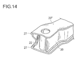
- FIG. 14 is an oblique perspective view of the cross member according to a further modification of the embodiment.
- a cross member 10 is a hollow member extending along a vehicle width direction X and including opening portions 11 at the end portions in the vehicle width direction X.
- the cross member 10 includes a cross member main body 20 , a closing plate 30 , cylindrical spacers 40 , a linking member 50 , and a bracket 60 .
- the cross member main body 20 includes an inner surface having a substantially U-shaped cross section perpendicular to the vehicle width direction X, the opening of the U facing a rear direction R of the vehicle and extending throughout the length of the cross member main body 20 along the vehicle width direction X.
- the cross member main body 20 further includes recessed portions 22 formed at both ends in the vehicle width direction X.
- the recessed portions 22 are provided on a side facing a front direction F opposite to the rear direction R in which the inner surface 21 is opened, and are recessed toward the inner surface side.
- the recessed portions 22 are tapered with increasing depth toward the ends along the vehicle width direction X.
- the direction in which the cross member main body 20 is opened is not limited to the rear direction R but may include the front direction F.
- holes 23 are formed in both sides in an up-down direction Z perpendicular to both the vehicle width direction X and the opening direction (rear direction R), into which holes 23 the cylindrical spacers 40 are inserted.
- protruding portions 24 are formed at a substantially central portion of the cross member main body 20 in the vehicle width direction X. The protruding portions 24 protrude on the inner surface 21 from both sides of the cross member main body 20 in the up-down direction Z such that the closing plate 30 can be touched on the protruding portions 24 (see FIG. 5 ).
- locating holes 25 for positioning the cross member main body 20 are formed when joining the closing plate 30 to the cross member main body 20 .
- the cylindrical spacers 40 include a cylindrical member linked to the vehicle body frame 100 via a bolt 101 (see FIG. 6 ) and including a through-hole 41 extending along the up-down direction Z.
- the cylindrical spacers 40 are disposed within the cross member main body 20 with the through-holes 41 communicated with the holes 23 in the sides in the up-down direction Z.
- the cylindrical spacers 40 are welded onto the cross member main body 20 at one or both ends of the cylindrical spacers 40 , thus forming a spacer weld portion 42 (see FIG. 4 ).
- the closing plate 30 includes a plate member extending along the vehicle width direction X.
- the closing plate 30 is disposed between the both sides of the cross member main body 20 in the up-down direction Z so as to close the inner surface 21 of the cross member main body 20 , with the edge portions welded onto the cross member main body 20 .
- the closing plate 30 meets the cross member main body 20 , thus forming closing plate weld portions 31 .
- locating holes 33 for positioning the closing plate 30 are formed when joining the closing plate 30 to the cross member main body 20 .
- a hole 32 is formed, through which the cylindrical linking member 50 is passed and welded therein, thus forming a first linking member weld portion 51 (see FIG. 5 ).
- the linking member 50 is also linked to the cross member main body 20 via a second linking member weld portion 52 .
- a Watt's linkage (not illustrated) connected to lateral links (not illustrated) may be linked.
- the substantially central portion of the closing plate 30 in the vehicle width direction X is touched on the protruding portions 24 of the cross member main body 20 , while the end portions of the closing plate 30 are touched on outer peripheral surfaces of the cylindrical spacers 40 , such that the closing plate 30 can be positioned with respect to the cross member main body 20 .
- the bracket 60 which is a member that can be linked to the Watt's linkage, is joined to the surface facing the front direction F of the cross member main body 20 by welding.
- the cross member main body 20 and the closing plate 30 may be obtained by forming a thin flat plate material (having a thickness t of 1.4 mm to 1.8 mm, for example).
- the jig 70 includes a flat mounting plate 72 with a mounting surface 71 for mounting the cross member main body 20 formed thereon; two locating pins 73 protruding from the mounting surface 71 of the mounting plate 72 ; and a rotating shaft 74 enabling the mounting plate 72 to be rotated.
- the locating pins 73 can be inserted into the locating holes 25 of the cross member main body 20 and the locating holes 33 of the closing plate 30 .
- the rotating shaft 74 may be pivotally mounted on fixed bearings (not illustrated) such that the posture of a member placed on the mounting plate 72 can be freely changed.
- a fixing means (not illustrated) for fixing the mounting plate 72 at an arbitrary rotational position may be provided.
- the cross member main body 20 and the closing plate 30 are formed from a flat-plate material.
- the linking member 50 and the cylindrical spacers 40 may be provisionally welded at one or two locations during the forming process.
- the mounting plate 72 is fixed in place with the mounting surface 71 facing upward as illustrated in FIG. 8 , and the cross member main body 20 is placed on the mounting plate 72 with the opening of the inner surface 21 facing upward.
- the locating pins 73 are inserted into the locating holes 25 of the cross member main body 20 so as to position the cross member main body 20 with respect to the mounting plate 72 .
- the linking member 50 provisionally welded to the cross member main body 20 may be permanently welded, thereby forming the second linking member weld portion 52 (see FIG. 5 ).
- the cylindrical spacers 40 provisionally welded to the cross member main body 20 may be permanently welded, thus forming the spacer weld portion 42 (see FIG. 4 ).
- the closing plate 30 is fitted on the open inner surface 21 of the cross member main body 20 , as illustrated in FIG. 9 , while the locating pins 73 are inserted into the locating holes 33 of the closing plate 30 .
- the substantially central portion of the closing plate 30 in the vehicle width direction X is touched on the protruding portions 24 of the cross member main body 20 (see FIG. 5 ).
- the end portions of the closing plate 30 are touched on the outer peripheral surfaces of the cylindrical spacers 40 (see FIG. 4 ).
- the closing plate 30 can be easily and accurately positioned with respect to the cross member main body 20 .
- the closing plate 30 is welded onto the cross member main body 20 , thereby forming a closing plate weld portion 31 as illustrated in FIG. 10 .
- the linking member 50 is welded onto the closing plate 30 , thus forming the first linking member weld portion 51 .
- the posture of the placed member such as the cross member main body 20
- the posture of the placed member may be changed as desired by rotating the mounting plate 72 so that the bracket 60 can be welded to the cross member main body 20 , thus completing the manufacture of the cross member 10 .
- the cross member 10 having a lightweight and sufficient rigidity can be manufactured easily and at low cost by adopting the hollow structure formed by welding the closing plate 30 to the cross member main body 20 having a substantially U-shaped cross section with the opening of the U facing one direction. Further, the recessed portions 22 and the cylindrical spacers 40 provided at the end portions of the cross member 10 decrease the opening area of the opening portions 11 and thereby prevent the entry of flying rocks into the cross member 10 .
- the closing plate 30 can be easily positioned with respect to the cross member main body 20 , so that the welding step can be simplified and the cross member 10 can be manufactured in less time and at lower cost. Furthermore, because the closing plate 30 is touched on the outer peripheral surfaces of the cylindrical spacers 40 fixed to the cross member main body 20 , the closing plate 30 can be positioned easily with respect to the cross member main body 20 . Thus, the step of welding the closing plate 30 to the cross member main body 20 can be simplified, so that the cross member 10 can be manufactured in less time and at lower cost.
- the cross member main body 20 has the substantially U-shaped cross section with the opening facing one direction, the cylindrical spacers 40 , the linking member 50 , and the closing plate 30 can be joined to the cross member main body 20 while the cross member main body 20 is fixed in a certain posture on the jig 70 .
- the cross member 10 can be manufactured in less time and at lower cost.
- the posture of the member placed on the jig 70 can be readily changed by rotating the jig 70 , allowing the bracket 60 to be easily joined to the cross member main body 20 .
- the hollow member including the cross member main body 20 and the closing plate 30 have a decreased rigidity in the up-down direction Z.
- the rigidity of the hollow member including the cross member main body 20 and the closing plate 30 is decreased, so that the cylindrical spacers 40 can be linked to the vehicle body frame 100 with an appropriate axial force.
- the linking portions have high fastening efficiency and provide a structure that is hard to loosen against external force.
- the cross member according to the present embodiment may be applied for purposes other than the cross member for suspensions.
- the cross member main body 20 has a substantially U-shaped cross section throughout the length in the vehicle width direction X
- the cross member main body 20 may have the substantially U-shape cross section only at the end portions in the vehicle width direction X.
- the cross member main body 20 may have a cross-sectional shape other than U-shape as long as the inner surface 21 is opened in one direction.
- a closing plate 30 ′ may be welded to the cylindrical spacers 40 , thus forming a second spacer weld portion 34 .
- a cross member main body 20 ′ may include a recessed portion 26 touching on the outer peripheral surface of the cylindrical spacers 40 .
- the recessed portion 26 may have a curvature along the shape of the outer peripheral surface of the cylindrical spacers 40 .
- the cylindrical spacers 40 can be easily positioned by simply touching the cylindrical spacers 40 on the cross member main body 20 ′.
- the step of welding the cylindrical spacers 40 to the cross member main body 20 ′ can be simplified, so that the cross member can be manufactured in less time and at lower cost.
- a cross member main body 20 ′ may include a folded portion 27 which is formed by folding the plate member at an edge extending along the vehicle width direction X. In this way, the rigidity of the cross member maybe increased.
- the present invention may be suitably applied for a suspension cross member for vehicle suspensions.
Landscapes
- Engineering & Computer Science (AREA)
- Chemical & Material Sciences (AREA)
- Combustion & Propulsion (AREA)
- Transportation (AREA)
- Mechanical Engineering (AREA)
- Body Structure For Vehicles (AREA)
Applications Claiming Priority (3)
| Application Number | Priority Date | Filing Date | Title |
|---|---|---|---|
| JP2011101927A JP5827032B2 (ja) | 2011-04-28 | 2011-04-28 | クロスメンバ |
| JP2011-101927 | 2011-04-28 | ||
| PCT/JP2011/062415 WO2012147214A1 (fr) | 2011-04-28 | 2011-05-30 | Traverse |
Publications (2)
| Publication Number | Publication Date |
|---|---|
| US20140145472A1 US20140145472A1 (en) | 2014-05-29 |
| US8905437B2 true US8905437B2 (en) | 2014-12-09 |
Family
ID=47071753
Family Applications (1)
| Application Number | Title | Priority Date | Filing Date |
|---|---|---|---|
| US13/878,446 Expired - Fee Related US8905437B2 (en) | 2011-04-28 | 2011-05-30 | Cross member |
Country Status (7)
| Country | Link |
|---|---|
| US (1) | US8905437B2 (fr) |
| EP (1) | EP2703255A4 (fr) |
| JP (1) | JP5827032B2 (fr) |
| KR (1) | KR101594328B1 (fr) |
| CN (1) | CN102858621A (fr) |
| RU (1) | RU2553486C1 (fr) |
| WO (1) | WO2012147214A1 (fr) |
Cited By (4)
| Publication number | Priority date | Publication date | Assignee | Title |
|---|---|---|---|---|
| US20140306418A1 (en) * | 2013-04-11 | 2014-10-16 | Audi Ag | Method for producing an air guide for a suspension arm and suspension arm with an air guide |
| US20150320149A1 (en) * | 2014-05-09 | 2015-11-12 | Ford Global Technologies, Llc | Variable radii flanges for mechanically retained crush tubes |
| USD749466S1 (en) * | 2014-09-08 | 2016-02-16 | Dennis Michael Nosworthy | Passenger vehicle chassis rear crossmember |
| US9902225B2 (en) * | 2014-03-08 | 2018-02-27 | Audi Ag | Cover for a chassis control arm |
Families Citing this family (4)
| Publication number | Priority date | Publication date | Assignee | Title |
|---|---|---|---|---|
| JP6410012B2 (ja) * | 2014-04-17 | 2018-10-24 | スズキ株式会社 | サスペンションフレームの構造 |
| ES2751728T3 (es) * | 2017-07-24 | 2020-04-01 | Autotech Eng Deutschland Gmbh | Falso chasis para un vehículo, en particular un vehículo eléctrico |
| USD949752S1 (en) * | 2020-11-16 | 2022-04-26 | Steve McGaughy | Crossmember for vehicle |
| CN121729354A (zh) * | 2023-08-25 | 2026-03-24 | 日产自动车株式会社 | 悬架安装构造 |
Citations (12)
| Publication number | Priority date | Publication date | Assignee | Title |
|---|---|---|---|---|
| JPS61202907U (fr) | 1985-06-07 | 1986-12-20 | ||
| US4909533A (en) * | 1987-07-27 | 1990-03-20 | Group Lotus PLC, of Norwich | Vehicle wheel suspension unit |
| JPH08164758A (ja) | 1994-12-12 | 1996-06-25 | Honda Motor Co Ltd | 燃料タンクの固定構造 |
| JPH08169360A (ja) | 1994-12-16 | 1996-07-02 | Honda Motor Co Ltd | 車両用サブフレーム構造 |
| JPH08169359A (ja) | 1994-12-16 | 1996-07-02 | Honda Motor Co Ltd | 車両用サブフレーム構造 |
| JP2006240535A (ja) | 2005-03-04 | 2006-09-14 | Honda Motor Co Ltd | インホールモータ装置 |
| US7201398B1 (en) * | 2002-10-23 | 2007-04-10 | Dana Corporation | Offset joint between structural members in a vehicle frame assembly to facilitate a coating process |
| US20100045072A1 (en) * | 2008-08-21 | 2010-02-25 | Mazda Motor Corporation | Frame structure of automotive vehicle |
| US7771137B2 (en) * | 2005-06-14 | 2010-08-10 | Nissan Motor Co., Ltd. | Connecting structure for hollow member or half hollow member |
| US7845662B2 (en) * | 2004-03-31 | 2010-12-07 | Honda Motor Co., Ltd. | Vehicle subframe and bush mounting structure |
| US20140021746A1 (en) * | 2011-05-17 | 2014-01-23 | Kirchhoff Automotive Deutschland Gmbh | Support used as a chassis component |
| US8690176B2 (en) * | 2009-03-20 | 2014-04-08 | Magna International Inc. | Suspension arm/link for motor vehicle and method for making same |
Family Cites Families (16)
| Publication number | Priority date | Publication date | Assignee | Title |
|---|---|---|---|---|
| JPS61202907A (ja) * | 1985-03-05 | 1986-09-08 | Mazda Motor Corp | 自動車のリヤサスペンシヨン |
| JP3448882B2 (ja) * | 1992-10-26 | 2003-09-22 | マツダ株式会社 | フレーム及び自動車の車体構造 |
| JPH0867269A (ja) * | 1994-08-31 | 1996-03-12 | Suzuki Motor Corp | 車両のサスペンションフレーム |
| DE19724624B4 (de) * | 1996-06-22 | 2010-09-30 | Volkswagen Ag | Längsträgerelement |
| DE19824637A1 (de) * | 1997-06-04 | 1998-12-10 | Dana Corp | Fahrzeug-Rahmen-Aufbau |
| KR100532358B1 (ko) * | 1998-09-21 | 2006-02-08 | 삼성전자주식회사 | 반도체 제조설비의 가스공급장치 및 가스공급방법 |
| US6183013B1 (en) * | 1999-07-26 | 2001-02-06 | General Motors Corporation | Hydroformed side rail for a vehicle frame and method of manufacture |
| RU2176606C2 (ru) * | 2000-02-07 | 2001-12-10 | Открытое акционерное общество "КАМАЗ" | Рама транспортного средства |
| KR100633902B1 (ko) * | 2004-03-11 | 2006-10-16 | 현대자동차주식회사 | 후륜 구동 차량의 리어 서브 프레임 |
| JP4418280B2 (ja) * | 2004-03-31 | 2010-02-17 | 本田技研工業株式会社 | 車両用サブフレーム |
| EP1731409B1 (fr) * | 2004-03-31 | 2011-12-28 | Honda Motor Co., Ltd. | Stucture de chassis de carrosserie de vehicule |
| JP4247902B2 (ja) * | 2004-03-31 | 2009-04-02 | 本田技研工業株式会社 | ブッシュ取付構造 |
| DE102005029292A1 (de) * | 2005-04-13 | 2006-10-19 | Audi Ag | Hilfsrahmen für ein Kraftfahrzeug |
| CN101224757B (zh) * | 2008-02-02 | 2010-08-18 | 宁波跃进汽车前桥有限公司 | 一种汽车前梁 |
| RU74363U1 (ru) * | 2008-02-12 | 2008-06-27 | Открытое акционерное общество "КАМАЗ" | Рама транспортного средства |
| JP5515510B2 (ja) * | 2009-08-21 | 2014-06-11 | 日産自動車株式会社 | 車体構造 |
-
2011
- 2011-04-28 JP JP2011101927A patent/JP5827032B2/ja not_active Expired - Fee Related
- 2011-05-30 EP EP11864577.9A patent/EP2703255A4/fr not_active Withdrawn
- 2011-05-30 KR KR1020127033519A patent/KR101594328B1/ko not_active Expired - Fee Related
- 2011-05-30 WO PCT/JP2011/062415 patent/WO2012147214A1/fr not_active Ceased
- 2011-05-30 US US13/878,446 patent/US8905437B2/en not_active Expired - Fee Related
- 2011-05-30 CN CN2011800157229A patent/CN102858621A/zh active Pending
- 2011-05-30 RU RU2013102954/11A patent/RU2553486C1/ru not_active IP Right Cessation
Patent Citations (12)
| Publication number | Priority date | Publication date | Assignee | Title |
|---|---|---|---|---|
| JPS61202907U (fr) | 1985-06-07 | 1986-12-20 | ||
| US4909533A (en) * | 1987-07-27 | 1990-03-20 | Group Lotus PLC, of Norwich | Vehicle wheel suspension unit |
| JPH08164758A (ja) | 1994-12-12 | 1996-06-25 | Honda Motor Co Ltd | 燃料タンクの固定構造 |
| JPH08169360A (ja) | 1994-12-16 | 1996-07-02 | Honda Motor Co Ltd | 車両用サブフレーム構造 |
| JPH08169359A (ja) | 1994-12-16 | 1996-07-02 | Honda Motor Co Ltd | 車両用サブフレーム構造 |
| US7201398B1 (en) * | 2002-10-23 | 2007-04-10 | Dana Corporation | Offset joint between structural members in a vehicle frame assembly to facilitate a coating process |
| US7845662B2 (en) * | 2004-03-31 | 2010-12-07 | Honda Motor Co., Ltd. | Vehicle subframe and bush mounting structure |
| JP2006240535A (ja) | 2005-03-04 | 2006-09-14 | Honda Motor Co Ltd | インホールモータ装置 |
| US7771137B2 (en) * | 2005-06-14 | 2010-08-10 | Nissan Motor Co., Ltd. | Connecting structure for hollow member or half hollow member |
| US20100045072A1 (en) * | 2008-08-21 | 2010-02-25 | Mazda Motor Corporation | Frame structure of automotive vehicle |
| US8690176B2 (en) * | 2009-03-20 | 2014-04-08 | Magna International Inc. | Suspension arm/link for motor vehicle and method for making same |
| US20140021746A1 (en) * | 2011-05-17 | 2014-01-23 | Kirchhoff Automotive Deutschland Gmbh | Support used as a chassis component |
Cited By (6)
| Publication number | Priority date | Publication date | Assignee | Title |
|---|---|---|---|---|
| US20140306418A1 (en) * | 2013-04-11 | 2014-10-16 | Audi Ag | Method for producing an air guide for a suspension arm and suspension arm with an air guide |
| US9227475B2 (en) * | 2013-04-11 | 2016-01-05 | Audi Ag | Method for producing an air guide for a suspension arm and suspension arm with an air guide |
| US9902225B2 (en) * | 2014-03-08 | 2018-02-27 | Audi Ag | Cover for a chassis control arm |
| US20150320149A1 (en) * | 2014-05-09 | 2015-11-12 | Ford Global Technologies, Llc | Variable radii flanges for mechanically retained crush tubes |
| US9578932B2 (en) * | 2014-05-09 | 2017-02-28 | Ford Global Technologies, Llc | Variable radii flanges for mechanically retained crush tubes |
| USD749466S1 (en) * | 2014-09-08 | 2016-02-16 | Dennis Michael Nosworthy | Passenger vehicle chassis rear crossmember |
Also Published As
| Publication number | Publication date |
|---|---|
| JP5827032B2 (ja) | 2015-12-02 |
| US20140145472A1 (en) | 2014-05-29 |
| RU2553486C1 (ru) | 2015-06-20 |
| WO2012147214A1 (fr) | 2012-11-01 |
| EP2703255A1 (fr) | 2014-03-05 |
| JP2012232655A (ja) | 2012-11-29 |
| KR101594328B1 (ko) | 2016-02-16 |
| EP2703255A4 (fr) | 2015-01-21 |
| CN102858621A (zh) | 2013-01-02 |
| KR20140004557A (ko) | 2014-01-13 |
Similar Documents
| Publication | Publication Date | Title |
|---|---|---|
| US8905437B2 (en) | Cross member | |
| US9963172B2 (en) | Body structure of vehicle | |
| CN105143020B (zh) | 车辆用副车架 | |
| US8540261B2 (en) | Suspension arm attachment structure | |
| WO2011122012A1 (fr) | Structure de sous-cadre de véhicule et son procédé de fabrication | |
| US12097742B2 (en) | Vehicle suspension arm | |
| CN102991584A (zh) | 车辆的前部本体结构 | |
| CN106882273A (zh) | 尾门构造 | |
| CN106184369A (zh) | 车辆用副车架 | |
| US20180111656A1 (en) | Drop-out structure for wheel alignment | |
| US9828029B2 (en) | Sub-frame for vehicle | |
| WO2012124692A1 (fr) | Structure de cadre de suspension | |
| CN101300145B (zh) | 悬架纵臂 | |
| CN112455542A (zh) | 车辆用副车架 | |
| US20170144503A1 (en) | Torsion beam suspension | |
| KR20130067446A (ko) | 캐리어 일체형 트레일링암의 링크 체결 구조 | |
| JP6627435B2 (ja) | ブレーキチャンバーブラケットの取付構造 | |
| CN106660422B (zh) | 扭转梁式悬架 | |
| CN103282262B (zh) | 悬架结构 | |
| JP4548175B2 (ja) | サスペンションロッド構造 | |
| CN110816665A (zh) | 车辆的连接结构 | |
| JP6136482B2 (ja) | サスペンションアーム取付構造 | |
| JP2015105727A (ja) | 車両用ブッシュおよびシャシフレーム支持構造 | |
| KR101624235B1 (ko) | 차량용 서브프레임의 구조 | |
| JP2010089601A (ja) | トーションビーム式サスペンションのアライメント調整機構 |
Legal Events
| Date | Code | Title | Description |
|---|---|---|---|
| AS | Assignment |
Owner name: YOROZU CORPORATION, JAPAN Free format text: ASSIGNMENT OF ASSIGNORS INTEREST;ASSIGNOR:TSUCHIYA, ATSUSHI;REEL/FRAME:030176/0304 Effective date: 20121228 |
|
| FEPP | Fee payment procedure |
Free format text: MAINTENANCE FEE REMINDER MAILED (ORIGINAL EVENT CODE: REM.) |
|
| LAPS | Lapse for failure to pay maintenance fees |
Free format text: PATENT EXPIRED FOR FAILURE TO PAY MAINTENANCE FEES (ORIGINAL EVENT CODE: EXP.); ENTITY STATUS OF PATENT OWNER: LARGE ENTITY |
|
| STCH | Information on status: patent discontinuation |
Free format text: PATENT EXPIRED DUE TO NONPAYMENT OF MAINTENANCE FEES UNDER 37 CFR 1.362 |
|
| FP | Lapsed due to failure to pay maintenance fee |
Effective date: 20181209 |