US8910321B2 - Universal flange apparatus for plumbing fixtures - Google Patents
Universal flange apparatus for plumbing fixtures Download PDFInfo
- Publication number
- US8910321B2 US8910321B2 US12/574,566 US57456609A US8910321B2 US 8910321 B2 US8910321 B2 US 8910321B2 US 57456609 A US57456609 A US 57456609A US 8910321 B2 US8910321 B2 US 8910321B2
- Authority
- US
- United States
- Prior art keywords
- flange
- end portion
- flexible sleeve
- arm portions
- flange apparatus
- Prior art date
- Legal status (The legal status is an assumption and is not a legal conclusion. Google has not performed a legal analysis and makes no representation as to the accuracy of the status listed.)
- Active, expires
Links
- 238000009428 plumbing Methods 0.000 title claims abstract description 28
- 239000000463 material Substances 0.000 claims abstract description 21
- 239000002699 waste material Substances 0.000 claims abstract description 6
- 238000000034 method Methods 0.000 claims description 13
- 238000007789 sealing Methods 0.000 claims description 9
- 238000005553 drilling Methods 0.000 claims description 4
- 238000009434 installation Methods 0.000 description 12
- XECAHXYUAAWDEL-UHFFFAOYSA-N acrylonitrile butadiene styrene Chemical compound C=CC=C.C=CC#N.C=CC1=CC=CC=C1 XECAHXYUAAWDEL-UHFFFAOYSA-N 0.000 description 2
- 239000004676 acrylonitrile butadiene styrene Substances 0.000 description 2
- 229920000122 acrylonitrile butadiene styrene Polymers 0.000 description 2
- 238000005516 engineering process Methods 0.000 description 2
- 238000003780 insertion Methods 0.000 description 2
- 230000037431 insertion Effects 0.000 description 2
- 230000007246 mechanism Effects 0.000 description 2
- 239000004800 polyvinyl chloride Substances 0.000 description 2
- 229920000915 polyvinyl chloride Polymers 0.000 description 2
- 229910001369 Brass Inorganic materials 0.000 description 1
- 230000004308 accommodation Effects 0.000 description 1
- 239000010951 brass Substances 0.000 description 1
- 238000012512 characterization method Methods 0.000 description 1
- 230000008602 contraction Effects 0.000 description 1
- 230000008878 coupling Effects 0.000 description 1
- 238000010168 coupling process Methods 0.000 description 1
- 238000005859 coupling reaction Methods 0.000 description 1
- 238000004519 manufacturing process Methods 0.000 description 1
- 238000012986 modification Methods 0.000 description 1
- 230000004048 modification Effects 0.000 description 1
- 230000008569 process Effects 0.000 description 1
- 238000004080 punching Methods 0.000 description 1
- 230000009467 reduction Effects 0.000 description 1
- 238000000926 separation method Methods 0.000 description 1
- 238000006467 substitution reaction Methods 0.000 description 1
- 239000012815 thermoplastic material Substances 0.000 description 1
Images


Classifications
-
- E—FIXED CONSTRUCTIONS
- E03—WATER SUPPLY; SEWERAGE
- E03D—WATER-CLOSETS OR URINALS WITH FLUSHING DEVICES; FLUSHING VALVES THEREFOR
- E03D11/00—Other component parts of water-closets, e.g. noise-reducing means in the flushing system, flushing pipes mounted in the bowl, seals for the bowl outlet, devices preventing overflow of the bowl contents; devices forming a water seal in the bowl after flushing, devices eliminating obstructions in the bowl outlet or preventing backflow of water and excrements from the waterpipe
- E03D11/13—Parts or details of bowls; Special adaptations of pipe joints or couplings for use with bowls, e.g. provisions in bowl construction preventing backflow of waste-water from the bowl in the flushing pipe or cistern, provisions for a secondary flushing, for noise-reducing
- E03D11/14—Means for connecting the bowl to the wall, e.g. to a wall outlet
-
- F—MECHANICAL ENGINEERING; LIGHTING; HEATING; WEAPONS; BLASTING
- F16—ENGINEERING ELEMENTS AND UNITS; GENERAL MEASURES FOR PRODUCING AND MAINTAINING EFFECTIVE FUNCTIONING OF MACHINES OR INSTALLATIONS; THERMAL INSULATION IN GENERAL
- F16L—PIPES; JOINTS OR FITTINGS FOR PIPES; SUPPORTS FOR PIPES, CABLES OR PROTECTIVE TUBING; MEANS FOR THERMAL INSULATION IN GENERAL
- F16L27/00—Adjustable joints; Joints allowing movement
- F16L27/10—Adjustable joints; Joints allowing movement comprising a flexible connection only
- F16L27/1012—Flanged joints
-
- F—MECHANICAL ENGINEERING; LIGHTING; HEATING; WEAPONS; BLASTING
- F16—ENGINEERING ELEMENTS AND UNITS; GENERAL MEASURES FOR PRODUCING AND MAINTAINING EFFECTIVE FUNCTIONING OF MACHINES OR INSTALLATIONS; THERMAL INSULATION IN GENERAL
- F16L—PIPES; JOINTS OR FITTINGS FOR PIPES; SUPPORTS FOR PIPES, CABLES OR PROTECTIVE TUBING; MEANS FOR THERMAL INSULATION IN GENERAL
- F16L27/00—Adjustable joints; Joints allowing movement
- F16L27/10—Adjustable joints; Joints allowing movement comprising a flexible connection only
- F16L27/107—Adjustable joints; Joints allowing movement comprising a flexible connection only the ends of the pipe being interconnected by a flexible sleeve
- F16L27/108—Adjustable joints; Joints allowing movement comprising a flexible connection only the ends of the pipe being interconnected by a flexible sleeve the sleeve having the form of a bellows with only one corrugation
Definitions
- the present disclosure generally relates to flanges, and more particularly to flanges for connecting plumbing fixtures of various sizes to a drainage system.
- flange apparatus have been used in the installation of plumbing fixtures to connect and secure the plumbing fixture to the drainage system of a building.
- a flange is often used to connect the discharge of wall-mounted urinals to the waste drain pipe within or behind the wall.
- flanges of various dimensions have been made available.
- the flange apparatus comprises a flange comprising a central portion and arm portions extending from the central portion, wherein the central portion comprises a central opening defined therethrough, and the arm portions each comprise an aperture defined therethrough, the aperture comprising substantially smooth surfaces and being operable to receive a fastener.
- the flange apparatus further comprises a flexible sleeve disposed through the central opening of the flange, the flexible sleeve comprising a first end portion mounted on an upper surface of the central portion of the flange.
- the first end portion comprises a ring protruding from a surface of the first end portion, the ring being operable to provide a seal between the flexible sleeve and the plumbing fixture.
- the flange apparatus comprises a flange comprising a central portion and arm portions extending from the central portion, wherein the central portion comprises a central opening defined therethrough, and the arm portions each comprise an aperture defined therethrough, the aperture comprising substantially smooth surfaces and being operable to receive a thread-forming fastener.
- the flange apparatus further comprises a flexible sleeve disposed through the central opening of the flange, the flexible sleeve comprising a first end portion mounted on an upper surface of the central portion of the flange.
- the first end portion comprises a ring protruding from a surface of the first end portion, the ring being operable to provide a seal between the flexible sleeve and the plumbing fixture.
- the arm portions are made of a threadable material such that threads are formed in the arm portions when the thread-forming fastener is received in the aperture of the arm portions.
- Yet another embodiment of the present disclosure is directed to a method for connecting a plumbing fixture discharge to a waste drain pipe.
- the method comprises providing a flange comprising a central portion and arm portions extending from the central portion, wherein the central portion comprises a central opening defined therethrough, and the arm portions each comprise an aperture defined therethrough, the aperture comprising substantially smooth surfaces.
- the method further comprises providing a flexible sleeve comprising first and second end portions, wherein the first end portion comprises a ring protruding from a surface of the first end portion, the ring being operable to provide a seal between the flexible sleeve and the plumbing fixture.
- the method further comprises seating the first end portion on a upper surface of the central portion of the flange and disposing the second end portion of the flexible sleeve through the central opening of the flange.
- the method further comprises connecting the second end portion of the flexible sleeve to the waste drain pipe.
- the method further comprises inserting fasteners through holes defined in the plumbing fixture and into the apertures of the arm portions of the flange, thereby connecting the first end portion of the sleeve to the plumbing fixture discharge.
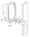
- FIG. 1 a is an exploded perspective view of a conventional flange apparatus
- FIG. 1 b is a perspective view of the flange apparatus shown in FIG. 1 a;
- FIG. 2 is an exploded view of another conventional flange apparatus
- FIG. 3 a is a perspective view of one embodiment of a flexible flange apparatus according to the present disclosure
- FIG. 3 b is a cut-away view of the flexible flange apparatus shown in FIG. 3 a according to the present disclosure
- FIG. 3 c is a cross-sectional view of the flexible flange apparatus shown in FIG. 3 a according to the present disclosure
- FIG. 4 a is a side view of an embodiment of the flange apparatus according to the present disclosure.
- FIG. 4 b is a perspective view of the flange apparatus shown in FIG. 4 a , according to the present disclosure
- FIG. 5 a is a perspective view of another embodiment of the flange apparatus according to the present disclosure.
- FIG. 5 b is a cut-away perspective view of the flange apparatus shown in FIG. 5 a;
- FIG. 6 a is an exploded view of a plumbing fixture installation comprising the flange apparatus of the present disclosure
- FIG. 6 b is an exploded view of another plumbing fixture installation comprising the flange apparatus of the present disclosure.
- FIG. 7 is a cross-section view of a flange apparatus coupled to a plumbing fixture, in accordance with the present disclosure.
- FIG. 1 a is an exploded perspective view of a conventional flange apparatus 100 and FIG. 1 b is a perspective view of the conventional flange apparatus shown in FIG. 1 a .
- Conventional rigid flange apparatus 100 is operable to connect the discharge of a urinal (not shown) to the drainage system (not shown) of a building.
- the conventional rigid flange apparatus 100 includes a flange 102 that is made of a rigid material.
- the flange 102 may be made of brass or rigid polymeric materials.
- Coupled to a first side of the flange 102 is a rigid connector 104 made of a rigid material.
- the rigid connector 104 has a first externally-threaded end portion 106 for coupling to the flange 102 and a second end portion 108 for providing a connection to the drain pipe.
- a gasket 110 is disposed on a second side of the flange 102 to provide a seal between discharge of the urinal and the flange 102 .
- the flange 102 includes arm portions 112 that extend outwardly, and the arm portions 112 each have at least one threaded bore 114 . To install the rigid flange apparatus 100 onto the urinal, screws 116 are inserted through openings (not shown) in the urinal and received by the threaded bores 114 .
- FIG. 2 illustrates another conventional rigid flange apparatus 200 , which includes a flange 202 and a gasket 203 .
- the flange 202 comprises outwardly extending arm portions 204 and a rigid body portion 212 .
- Arm portions 204 of the flange 202 each comprise a slit 206 instead of a threaded bore, and screws 208 are inserted through the slits 206 .
- the gasket 203 is first disposed on a top surface of the flange 202 , and the screws 208 are then inserted through both the slits 206 and the corresponding bores (not shown) in the urinal from a first side of the urinal.
- Nuts 210 are disposed over the screws 208 on a second side of the urinal to tightly secure the flange 202 to the urinal. Washers may be disposed between the head of the screws 208 and the flange 202 and between the nuts 210 and the urinal. Nuts 210 are used to secure the screws 208 because the slits 206 are not threaded.
- the installation of the urinal requires precise alignment of the urinal, the flange apparatus, and the drainage pipe in the drainage system. But the precision required is impractical due to various sources of misalignment.
- the drainage pipe in the drainage system could have various degrees of inclination, or there may be height adjustment errors inherent in the fixing of the urinal to the wall.
- the flange apparatus 100 comprises threaded bores 114 for receiving screws 116 that are disposed through corresponding openings in the urinal.
- the threaded bores 114 are spaced apart by a fixed distance.
- the flange apparatus 100 can only accommodate urinals whose corresponding openings are spaced apart by the same distance.
- a different flange apparatus of a different size would have to be obtained for urinals not having matching dimensions.
- the flange apparatus 200 is configured to have slits 206 to provide some accommodation for the different distances between the openings in the urinal for receiving the screws 208 , the use of washers and nuts 210 is cumbersome and increases the difficulty of installation.
- FIGS. 1( a ), 1 ( b ) Another disadvantage of the conventional rigid flange apparatus 100 and 200 is the additional sources of leakage that may result from connecting multiple parts to form a conduit between the urinal and the drainage system.
- FIGS. 1( a ), 1 ( b ) connecting a gasket 110 , a flange 102 , and a connector 104 presents two additional sources of leakage between the urinal and the drainage system.
- Connecting the gasket 203 and the flange 202 as shown in FIG. 2 presents an additional source of leakage.
- FIG. 3 a is a perspective view of one embodiment of a flexible flange apparatus 300 .
- FIG. 3 b is a cut-away view of the flexible flange apparatus 300
- FIG. 3 c is a cross-sectional view of the flexible flange apparatus 300 .
- the flexible flange apparatus 300 includes a flange 302 comprising a central opening and a flexible sleeve 304 mounted on the flange 302 , in which the body 306 of the flexible sleeve 304 extends through the central opening of the flange 302 .
- the flange 302 and the flexible sleeve 304 may be integrally formed or removably coupled.
- the flexible sleeve is seated on a recessed area defined in the flange 302 .
- the recess area may be defined, in part, by a central portion 316 and arm portions 318 of the flange 302 , with the upper surface of the arm portions 318 being elevated relative to an upper surface of the central portion 316 .
- Such a recessed area allows the flexible sleeve 304 to be securely mounted on the flange 302 . Additional descriptions of the central and arm portions 316 and 318 are provided in a later portion of the present disclosure.
- the diameter of the recessed area may be substantially the same as the outer diameter of a first end portion 308 of the flexible sleeve 304 .
- the sleeve 304 includes a first end portion 308 comprising at least one concentric ring 310 .
- the sleeve 304 comprises a plurality of concentric rings 310 .
- the concentric rings 310 may include members protruding upwardly from the top surface of the end portion 308 and forming a plurality of concentric rings operable to provide a substantially sealed connection between the discharge of a urinal and the sleeve 304 . It will be appreciated that the substantially sealed connection may also be provided in other ways, such as by providing a gasket (e.g., the gasket 110 ) at the surface 311 .
- a gasket e.g., the gasket 110
- An inner wall of the sleeve 304 in a longitudinal direction may be generally linear (i.e., without corrugations).
- the sleeve 304 further includes a second end portion 312 having a sealing element 314 on the outer surface of the sleeve 304 , and the sealing element 314 is operable to substantially seal the connection between the sleeve 304 and the drain pipe of the drainage system.
- FIG. 4 a is a side view of an embodiment of a flexible flange apparatus 400 , showing a perspective view of the flexible sleeve 304 , which is made of a substantially flexible material that allows it to be distorted during installation.
- the flexible sleeve 304 may in some installations have a non-distorted longitudinal axis 360 , and in other installations, have be angularly distorted, such that the flexible sleeve 304 has a distorted longitudinal axis 362 .
- the body 306 of the sleeve 304 is sufficiently flexible to achieve non-negligible angles of deflection ⁇ relative to a non-distorted longitudinal axis 360 .
- a non-negligible angle of deflection ⁇ may be ten degrees or more of deflection of one end of the sleeve 304 relative to an opposing end of the sleeve 304 as illustrated in FIG. 4( a ).
- FIG. 4( b ) is a perspective view of the distorted sleeve 304 shown in FIG. 4( a ).
- the sleeve 304 may be formed of various materials to permit non-negligible flexibility.
- the sleeve 304 may be formed of materials having a hardness ranging from 35 shore A to 90 shore A, or from 35 shore A to 65 shore A, or more specifically about 50 shore A.
- the sleeve 304 may be formed of uniform material that would lead to a reduction in manufacturing costs and the likelihood of error during installation.
- the sleeve 304 may be of any suitable length. In a preferred embodiment, the sleeve 304 is 2-4 inches in length.
- the flange 302 of the flexible flange apparatus 300 includes a central portion 316 and arm portions 318 extending from the central portion 316 .
- the arm portions 318 include apertures 320 that are operable to receive fasteners (not shown).
- the surfaces of the apertures 320 are substantially smooth and are not threaded, and the fasteners can be received anywhere along the apertures 320 .
- the apertures 320 comprise elongated apertures extending along the length of the arm portions 318 .
- the width 322 of the apertures 320 is smaller than the diameter of the fasteners, but the arm portions 318 are made of a material that can be deformed to accommodate the fasteners being inserted into the aperture 320 .
- the arm portions 318 are made of a threadable material that can be threaded with a thread-forming fastener without the use of a drill bit.
- a suitable threadable material include thermoplastic materials (e.g., polyvinyl chloride (“PVC”) or acrylonitrile butadiene styrene (“ABS”)), and arm portions 318 may be made of the same or different materials.
- Suitable fasteners include various threaded screws known in the art, and the insertion of the threaded screws may be accomplished by drilling the threaded screws through the apertures 320 .
- the fasteners may comprise unthreaded nails, and the insertion of the nails may be accomplished by forcibly punching the nail into the narrower aperture 320 using a hammer.
- apertures 320 guide and facilitate the drilling of the screws, and the fasteners can be inserted anywhere along the apertures 320 .
- the nails and the arm portions may be modified to include a lock-and-release mechanism to prevent the nails from loosening over time and still allow the removal of the nails when the urinal needs to be removed from the wall.
- the nails and the arm portions may cooperate to form a releasable ratchet mechanism that will allow the nails to be inserted but not loosen unless the ratchet is released.
- the flexible flange apparatus 300 can be modified according to the principles disclosed herein to achieve various desired design needs. For instance, another exemplary embodiment of the flexible flange apparatus of the present disclosure is provided with reference to FIGS. 5( a ) and ( b ).
- the illustrated embodiment comprises a flexible flange apparatus 450 , which includes a flange 402 comprising a central opening and a flexible sleeve 404 mounted on the flange 402 , in which the body 406 of the flexible sleeve 404 extends through the central opening of the flange 402 .
- the flexible sleeve 404 may be made of any flexible material discussed in the present disclosure, and additionally, the body 406 may include a corrugated portion 452 to improve the flexibility of the sleeve 404 .
- the sleeve 404 may include a first end portion 408 having at least one concentric ring 410 .
- the sleeve 404 may include a plurality of concentric rings 410 comprising a member protruding upwardly from the top surface of the end portion 408 and forming a plurality of concentric rings.
- the sleeve 404 may further include a second end portion 412 having a sealing element 414 on the outer surface of the sleeve 404 .
- the flange 402 of the flexible flange apparatus 450 may include a central portion 416 and arm portions 418 extending from the central portion 416 .
- the arm portions 418 may include apertures 420 that are operable to receive fasteners, such as nails or threaded screws (not shown).
- the installation of the urinal 330 generally involves connecting the second end portion 312 of the flexible flange apparatus 300 or 400 to the drain pipe 338 , mounting the urinal 330 on the wall 336 , and connecting the first end portion 308 of the flange apparatus 300 to the urinal 330 .
- the discharge of urinal 330 and the drain pipe 338 often do not align properly due to human errors in the mounting of the urinal 330 and the inclination of the drain pipe 338 .
- the flexibility of the sleeve 304 allows the second end portion 312 to be adjusted to a variety of orientations relative to the first end portion 308 to accommodate for the misalignment of the urinal 330 and drain pipe 338 .
- the sleeve 304 can be bent at an angle to accommodate for the inclination of the drain pipe 338 as illustrated in FIG. 6( b ). It is also to be appreciated that the flexibility of the sleeve 304 reduces the number of potential sources of leakage by eliminating the need for additional connectors to accommodate the misalignment between a flange apparatus and the drain pipe.
- the flexible sleeve 304 provides one continuous leak-proof conduit from the urinal to the plumbing system of the building. It should also be appreciated that the flexibility of the sleeve 304 also allows for some freedom of movement caused by the varying and unequal expansion and contraction of different materials through a range of temperatures.
- the screws 334 may be thread-forming screws known in the art that are operable to be drilled through a medium.
- the screws 334 each have a pointed tip as shown in FIGS. 6( a ), 6 ( b ), and 7 to facilitate the drilling.
- the urinal 330 has two bores 332 that allow the screws 334 to be inserted through the urinal 330 and drilled through the apertures 320 into the arm portions of the flange 302 . As the screws are tightened, the flange 302 presses the concentric rings 310 tightly against the discharge of the urinal, thereby forming a substantially sealed connection.
- the concentric rings 310 thus eliminate the need for an additional part—a gasket—to seal the flange-urinal connection, which would be a source of leakage if present. It is also to be appreciated that since the screws 334 can be received anywhere along the apertures 320 , the flexible flange apparatus 300 can be connected to urinals that were made by different manufacturers and have different separations between the bores 332 .
Landscapes
- Engineering & Computer Science (AREA)
- General Engineering & Computer Science (AREA)
- Mechanical Engineering (AREA)
- Health & Medical Sciences (AREA)
- Life Sciences & Earth Sciences (AREA)
- Hydrology & Water Resources (AREA)
- Public Health (AREA)
- Water Supply & Treatment (AREA)
- Sanitary Device For Flush Toilet (AREA)
- Sink And Installation For Waste Water (AREA)
- Branch Pipes, Bends, And The Like (AREA)
- Gasket Seals (AREA)
Priority Applications (1)
| Application Number | Priority Date | Filing Date | Title |
|---|---|---|---|
| US12/574,566 US8910321B2 (en) | 2008-10-06 | 2009-10-06 | Universal flange apparatus for plumbing fixtures |
Applications Claiming Priority (2)
| Application Number | Priority Date | Filing Date | Title |
|---|---|---|---|
| US10313108P | 2008-10-06 | 2008-10-06 | |
| US12/574,566 US8910321B2 (en) | 2008-10-06 | 2009-10-06 | Universal flange apparatus for plumbing fixtures |
Publications (2)
| Publication Number | Publication Date |
|---|---|
| US20100088811A1 US20100088811A1 (en) | 2010-04-15 |
| US8910321B2 true US8910321B2 (en) | 2014-12-16 |
Family
ID=42097538
Family Applications (1)
| Application Number | Title | Priority Date | Filing Date |
|---|---|---|---|
| US12/574,566 Active 2032-05-13 US8910321B2 (en) | 2008-10-06 | 2009-10-06 | Universal flange apparatus for plumbing fixtures |
Country Status (7)
| Country | Link |
|---|---|
| US (1) | US8910321B2 (pt) |
| AR (1) | AR074256A1 (pt) |
| BR (1) | BRPI0920017A2 (pt) |
| CA (1) | CA2739785C (pt) |
| MX (1) | MX2011003645A (pt) |
| PE (1) | PE20120134A1 (pt) |
| WO (1) | WO2010041142A1 (pt) |
Cited By (8)
| Publication number | Priority date | Publication date | Assignee | Title |
|---|---|---|---|---|
| USD728759S1 (en) * | 2014-07-07 | 2015-05-05 | Coflex S.A. De C.V. | Universal height absorbing toilet seal |
| USD730498S1 (en) * | 2014-07-07 | 2015-05-26 | Coflex S.A. De C.V. | Universal height absorbing toilet seal with sleeve |
| USD792563S1 (en) * | 2015-12-10 | 2017-07-18 | Coflex S.A. De C.V. | Universal height absorbing toilet seal with tapered sleeve |
| US10774515B1 (en) | 2019-02-26 | 2020-09-15 | Kenny Esquivel | Elongated toilet flange |
| USD927655S1 (en) | 2019-05-09 | 2021-08-10 | Coflex S.A. De C.V. | Universal height absorbing toilet seal |
| US11111663B2 (en) | 2017-09-15 | 2021-09-07 | Kohler Co. | Urinal with trapway connection system |
| US20210300564A1 (en) * | 2020-03-31 | 2021-09-30 | Airbus Operations Gmbh | Wastewater tank arrangement for an aircraft |
| US20250129589A1 (en) * | 2023-10-21 | 2025-04-24 | Carlos Castaneda | Offset piping device |
Families Citing this family (11)
| Publication number | Priority date | Publication date | Assignee | Title |
|---|---|---|---|---|
| US7814580B2 (en) | 2003-02-20 | 2010-10-19 | Coflex S.A. De C.V. | Flexible flange apparatus for connecting conduits and methods for connecting same |
| US9695787B2 (en) * | 2013-05-28 | 2017-07-04 | Ford Global Technologies, Llc | Sealing solution for reduced diameter intake manifold post |
| USD798422S1 (en) * | 2013-11-07 | 2017-09-26 | Samuel D. Yarborough | Drain flange |
| US20150143622A1 (en) * | 2013-11-25 | 2015-05-28 | Andrew Scott Lacy | Urinal Repair Apparatus |
| US9783976B2 (en) * | 2014-04-15 | 2017-10-10 | Coflex S.A. De C.V. | Universal height absorbing toilet seal |
| US11268270B2 (en) | 2014-04-15 | 2022-03-08 | Coflex S.A. De C.V. | Universal height absorbing toilet seal |
| US10294647B2 (en) | 2014-04-15 | 2019-05-21 | Coflex S.A. De C.V. | Universal height absorbing toilet seal |
| USD794760S1 (en) * | 2015-12-10 | 2017-08-15 | Coflex S.A. De C.V. | Dual use plumbing handle with curved wings |
| USD795399S1 (en) * | 2015-12-11 | 2017-08-22 | Coflex S.A. De C.V. | Dual use plumbing handle with straight wings |
| USD1041621S1 (en) * | 2022-08-22 | 2024-09-10 | Scatter, LLC | Connector for transfer of fluid |
| CN219753394U (zh) * | 2023-05-30 | 2023-09-26 | 科勒(中国)投资有限公司 | 一种排污结构及小便器 |
Citations (13)
| Publication number | Priority date | Publication date | Assignee | Title |
|---|---|---|---|---|
| US961685A (en) * | 1909-09-10 | 1910-06-14 | Joseph J Cosgrove | Water-closet connection. |
| US2743460A (en) | 1953-08-03 | 1956-05-01 | Leonard W Youngstrom | Adjustable connector for tank and bowl of a close coupled water-closet combination |
| US3727955A (en) * | 1972-03-22 | 1973-04-17 | E Carter | Semiflexible fluid-tight tube coupling |
| US3891007A (en) * | 1972-07-03 | 1975-06-24 | Dayco Corp | Exteriorly corrugated hose of composite materials |
| US4185334A (en) * | 1978-11-21 | 1980-01-29 | Izzi Lewis B | Wall urinal mounting flange |
| US4355828A (en) * | 1976-09-27 | 1982-10-26 | Taunton Raymond F | Universal plastic flange for connecting urinals to drain pipes |
| US4445237A (en) | 1982-08-30 | 1984-05-01 | Partnership Of Robert M. Paul | Close coupled water-closet combination and adapter |
| US4516278A (en) * | 1980-03-03 | 1985-05-14 | Lamond Lee T | Flexible plumbing trap |
| US6719294B2 (en) * | 2000-02-04 | 2004-04-13 | Fluidmaster, Inc. | Bathroom fixture gasket apparatus and method |
| US6764263B2 (en) * | 2000-01-11 | 2004-07-20 | Sala Carlo | Self-threading screw provided with a point and apparatus to produce it |
| US20050278841A1 (en) * | 2003-02-20 | 2005-12-22 | Coflex S.A. De C.V. | Flexible flange apparatus for connecting conduits and methods for connecting same |
| US20060145428A1 (en) * | 2004-12-30 | 2006-07-06 | Dudman Richard L | Gasket ring with sharp peaks |
| US7188376B2 (en) * | 2003-02-20 | 2007-03-13 | Coflex S.A. De C.V. | Flexible sleeve for connection to a plumbing fixture |
Family Cites Families (4)
| Publication number | Priority date | Publication date | Assignee | Title |
|---|---|---|---|---|
| US2985291A (en) * | 1958-04-28 | 1961-05-23 | Schoepe Adolf | Composite seal construction |
| US4197889A (en) * | 1978-10-20 | 1980-04-15 | C. Hager & Sons Hinge Manufacturing Company | Security screw, driver therefor, and process |
| US4823527A (en) * | 1985-12-12 | 1989-04-25 | Harbeke Gerold J | Plumbing concrete form accessory |
| US5304018A (en) * | 1992-03-20 | 1994-04-19 | Lavanchy Wayne N | Plunge cutting device and method for plastic pipe members such as pipe couplings, flanges, hubs, and the like |
-
2009
- 2009-10-06 AR ARP090103846A patent/AR074256A1/es unknown
- 2009-10-06 CA CA2739785A patent/CA2739785C/en active Active
- 2009-10-06 BR BRPI0920017A patent/BRPI0920017A2/pt not_active IP Right Cessation
- 2009-10-06 US US12/574,566 patent/US8910321B2/en active Active
- 2009-10-06 PE PE2011000854A patent/PE20120134A1/es active IP Right Grant
- 2009-10-06 WO PCT/IB2009/007185 patent/WO2010041142A1/en not_active Ceased
- 2009-10-06 MX MX2011003645A patent/MX2011003645A/es active IP Right Grant
Patent Citations (14)
| Publication number | Priority date | Publication date | Assignee | Title |
|---|---|---|---|---|
| US961685A (en) * | 1909-09-10 | 1910-06-14 | Joseph J Cosgrove | Water-closet connection. |
| US2743460A (en) | 1953-08-03 | 1956-05-01 | Leonard W Youngstrom | Adjustable connector for tank and bowl of a close coupled water-closet combination |
| US3727955A (en) * | 1972-03-22 | 1973-04-17 | E Carter | Semiflexible fluid-tight tube coupling |
| US3891007A (en) * | 1972-07-03 | 1975-06-24 | Dayco Corp | Exteriorly corrugated hose of composite materials |
| US4355828A (en) * | 1976-09-27 | 1982-10-26 | Taunton Raymond F | Universal plastic flange for connecting urinals to drain pipes |
| US4185334A (en) * | 1978-11-21 | 1980-01-29 | Izzi Lewis B | Wall urinal mounting flange |
| US4516278A (en) * | 1980-03-03 | 1985-05-14 | Lamond Lee T | Flexible plumbing trap |
| US4445237A (en) | 1982-08-30 | 1984-05-01 | Partnership Of Robert M. Paul | Close coupled water-closet combination and adapter |
| US6764263B2 (en) * | 2000-01-11 | 2004-07-20 | Sala Carlo | Self-threading screw provided with a point and apparatus to produce it |
| US6719294B2 (en) * | 2000-02-04 | 2004-04-13 | Fluidmaster, Inc. | Bathroom fixture gasket apparatus and method |
| US20050278841A1 (en) * | 2003-02-20 | 2005-12-22 | Coflex S.A. De C.V. | Flexible flange apparatus for connecting conduits and methods for connecting same |
| US7188376B2 (en) * | 2003-02-20 | 2007-03-13 | Coflex S.A. De C.V. | Flexible sleeve for connection to a plumbing fixture |
| US7814580B2 (en) * | 2003-02-20 | 2010-10-19 | Coflex S.A. De C.V. | Flexible flange apparatus for connecting conduits and methods for connecting same |
| US20060145428A1 (en) * | 2004-12-30 | 2006-07-06 | Dudman Richard L | Gasket ring with sharp peaks |
Non-Patent Citations (1)
| Title |
|---|
| Applicants Admitted prior art, Fig. 1a of the instant application. * |
Cited By (12)
| Publication number | Priority date | Publication date | Assignee | Title |
|---|---|---|---|---|
| USD728759S1 (en) * | 2014-07-07 | 2015-05-05 | Coflex S.A. De C.V. | Universal height absorbing toilet seal |
| USD730498S1 (en) * | 2014-07-07 | 2015-05-26 | Coflex S.A. De C.V. | Universal height absorbing toilet seal with sleeve |
| USD792563S1 (en) * | 2015-12-10 | 2017-07-18 | Coflex S.A. De C.V. | Universal height absorbing toilet seal with tapered sleeve |
| USD857860S1 (en) * | 2015-12-10 | 2019-08-27 | Coflex S.A. De C.V. | Universal height absorbing toilet seal with tapered sleeve |
| US11111663B2 (en) | 2017-09-15 | 2021-09-07 | Kohler Co. | Urinal with trapway connection system |
| US10774515B1 (en) | 2019-02-26 | 2020-09-15 | Kenny Esquivel | Elongated toilet flange |
| USD927655S1 (en) | 2019-05-09 | 2021-08-10 | Coflex S.A. De C.V. | Universal height absorbing toilet seal |
| USD1089569S1 (en) | 2019-05-09 | 2025-08-19 | Coflex S.A. De C.V. | Toilet seal |
| US20210300564A1 (en) * | 2020-03-31 | 2021-09-30 | Airbus Operations Gmbh | Wastewater tank arrangement for an aircraft |
| US11691734B2 (en) * | 2020-03-31 | 2023-07-04 | Airbus Operations Gmbh | Wastewater tank arrangement for an aircraft |
| US20250129589A1 (en) * | 2023-10-21 | 2025-04-24 | Carlos Castaneda | Offset piping device |
| US12492543B2 (en) * | 2023-10-21 | 2025-12-09 | Carlos Castaneda | Offset piping device |
Also Published As
| Publication number | Publication date |
|---|---|
| US20100088811A1 (en) | 2010-04-15 |
| WO2010041142A1 (en) | 2010-04-15 |
| CA2739785C (en) | 2015-03-31 |
| PE20120134A1 (es) | 2012-02-20 |
| BRPI0920017A2 (pt) | 2016-08-30 |
| CA2739785A1 (en) | 2010-04-15 |
| AR074256A1 (es) | 2011-01-05 |
| MX2011003645A (es) | 2011-05-25 |
Similar Documents
| Publication | Publication Date | Title |
|---|---|---|
| US8910321B2 (en) | Universal flange apparatus for plumbing fixtures | |
| US10633850B2 (en) | Flexible flange apparatus for connecting conduits and methods for connecting same | |
| US12454819B2 (en) | Pipe connector | |
| US20190106870A1 (en) | Flexible drainage trap | |
| US9145665B2 (en) | Adjustable locking spout shank | |
| US10851534B2 (en) | Wall hung toilet assembly with a sloped gasket | |
| US6840267B1 (en) | Connection kit for a bath spout | |
| US20240376697A1 (en) | Systems and methods for coupling of a tub spout | |
| US20100306968A1 (en) | Hose joint clamp | |
| KR100486920B1 (ko) | 용수관 설치용 분기구 | |
| EP2459810B1 (en) | Toilet pan connector | |
| KR101051082B1 (ko) | 파이프 연결장치 | |
| CN205877534U (zh) | 便捷式卡扣连接装置 | |
| KR100555145B1 (ko) | 상수도관 연결구조 | |
| JPH09105482A (ja) | 管継手 | |
| KR20010067996A (ko) | 가요관 연결용 조인트 | |
| KR100779702B1 (ko) | 길이 조정가능한 배관 연결장치 | |
| JP6177716B2 (ja) | マンホールに接続する下水道本管の取付装置 | |
| JP2008151323A (ja) | 樹脂管組込型バルブ、及びバルブと樹脂管との接続構造 | |
| KR100891151B1 (ko) | 이중벽관의 관 이음장치 및 이를 이용한 관 이음방법 | |
| JP2003003506A (ja) | リブパイプとマンホールの接続構造及び拡径バンド | |
| JPH02248791A (ja) | 水栓・ガス栓の配管・取付工法 | |
| JP2006283357A (ja) | 流体管の中継接続具 | |
| KR20100009165U (ko) | 고정력이 향상된 관 연결구 및 이를 위한 고정장치 | |
| JPH02248789A (ja) | 水栓・ガス栓継手 |
Legal Events
| Date | Code | Title | Description |
|---|---|---|---|
| AS | Assignment |
Owner name: COFLEX S.A. DE C.V.,MEXICO Free format text: ASSIGNMENT OF ASSIGNORS INTEREST;ASSIGNORS:CORONADO, EDUARDO;FLORES-VILLARREAL, HUMBERTO;SADA, JORGE;AND OTHERS;SIGNING DATES FROM 20081007 TO 20081009;REEL/FRAME:023867/0920 Owner name: COFLEX S.A. DE C.V., MEXICO Free format text: ASSIGNMENT OF ASSIGNORS INTEREST;ASSIGNORS:CORONADO, EDUARDO;FLORES-VILLARREAL, HUMBERTO;SADA, JORGE;AND OTHERS;SIGNING DATES FROM 20081007 TO 20081009;REEL/FRAME:023867/0920 |
|
| STCF | Information on status: patent grant |
Free format text: PATENTED CASE |
|
| FEPP | Fee payment procedure |
Free format text: PAT HOLDER NO LONGER CLAIMS SMALL ENTITY STATUS, ENTITY STATUS SET TO UNDISCOUNTED (ORIGINAL EVENT CODE: STOL); ENTITY STATUS OF PATENT OWNER: LARGE ENTITY |
|
| MAFP | Maintenance fee payment |
Free format text: PAYMENT OF MAINTENANCE FEE, 4TH YEAR, LARGE ENTITY (ORIGINAL EVENT CODE: M1551) Year of fee payment: 4 |
|
| MAFP | Maintenance fee payment |
Free format text: PAYMENT OF MAINTENANCE FEE, 8TH YEAR, LARGE ENTITY (ORIGINAL EVENT CODE: M1552); ENTITY STATUS OF PATENT OWNER: LARGE ENTITY Year of fee payment: 8 |