US8931962B2 - Dual orientation connector with side contacts - Google Patents
Dual orientation connector with side contacts Download PDFInfo
- Publication number
- US8931962B2 US8931962B2 US13/704,236 US201113704236A US8931962B2 US 8931962 B2 US8931962 B2 US 8931962B2 US 201113704236 A US201113704236 A US 201113704236A US 8931962 B2 US8931962 B2 US 8931962B2
- Authority
- US
- United States
- Prior art keywords
- connector
- tab
- contacts
- plug connector
- plug
- Prior art date
- Legal status (The legal status is an assumption and is not a legal conclusion. Google has not performed a legal analysis and makes no representation as to the accuracy of the status listed.)
- Expired - Fee Related, expires
Links
Images




Classifications
-
- H—ELECTRICITY
- H01—ELECTRIC ELEMENTS
- H01R—ELECTRICALLY-CONDUCTIVE CONNECTIONS; STRUCTURAL ASSOCIATIONS OF A PLURALITY OF MUTUALLY-INSULATED ELECTRICAL CONNECTING ELEMENTS; COUPLING DEVICES; CURRENT COLLECTORS
- H01R24/00—Two-part coupling devices, or either of their cooperating parts, characterised by their overall structure
- H01R24/58—Contacts spaced along longitudinal axis of engagement
-
- H—ELECTRICITY
- H01—ELECTRIC ELEMENTS
- H01R—ELECTRICALLY-CONDUCTIVE CONNECTIONS; STRUCTURAL ASSOCIATIONS OF A PLURALITY OF MUTUALLY-INSULATED ELECTRICAL CONNECTING ELEMENTS; COUPLING DEVICES; CURRENT COLLECTORS
- H01R24/00—Two-part coupling devices, or either of their cooperating parts, characterised by their overall structure
-
- G—PHYSICS
- G02—OPTICS
- G02B—OPTICAL ELEMENTS, SYSTEMS OR APPARATUS
- G02B6/00—Light guides; Structural details of arrangements comprising light guides and other optical elements, e.g. couplings
- G02B6/24—Coupling light guides
- G02B6/36—Mechanical coupling means
-
- G—PHYSICS
- G02—OPTICS
- G02B—OPTICAL ELEMENTS, SYSTEMS OR APPARATUS
- G02B6/00—Light guides; Structural details of arrangements comprising light guides and other optical elements, e.g. couplings
- G02B6/24—Coupling light guides
- G02B6/36—Mechanical coupling means
- G02B6/38—Mechanical coupling means having fibre to fibre mating means
- G02B6/3807—Dismountable connectors, i.e. comprising plugs
- G02B6/381—Dismountable connectors, i.e. comprising plugs of the ferrule type, e.g. fibre ends embedded in ferrules, connecting a pair of fibres
- G02B6/3817—Dismountable connectors, i.e. comprising plugs of the ferrule type, e.g. fibre ends embedded in ferrules, connecting a pair of fibres containing optical and electrical conductors
-
- H—ELECTRICITY
- H01—ELECTRIC ELEMENTS
- H01R—ELECTRICALLY-CONDUCTIVE CONNECTIONS; STRUCTURAL ASSOCIATIONS OF A PLURALITY OF MUTUALLY-INSULATED ELECTRICAL CONNECTING ELEMENTS; COUPLING DEVICES; CURRENT COLLECTORS
- H01R13/00—Details of coupling devices of the kinds covered by groups H01R12/70 or H01R24/00 - H01R33/00
- H01R13/40—Securing contact members in or to a base or case; Insulating of contact members
- H01R13/405—Securing in non-demountable manner, e.g. moulding, riveting
-
- H—ELECTRICITY
- H01—ELECTRIC ELEMENTS
- H01R—ELECTRICALLY-CONDUCTIVE CONNECTIONS; STRUCTURAL ASSOCIATIONS OF A PLURALITY OF MUTUALLY-INSULATED ELECTRICAL CONNECTING ELEMENTS; COUPLING DEVICES; CURRENT COLLECTORS
- H01R13/00—Details of coupling devices of the kinds covered by groups H01R12/70 or H01R24/00 - H01R33/00
- H01R13/62—Means for facilitating engagement or disengagement of coupling parts or for holding them in engagement
- H01R13/627—Snap or like fastening
- H01R13/6271—Latching means integral with the housing
-
- H—ELECTRICITY
- H01—ELECTRIC ELEMENTS
- H01R—ELECTRICALLY-CONDUCTIVE CONNECTIONS; STRUCTURAL ASSOCIATIONS OF A PLURALITY OF MUTUALLY-INSULATED ELECTRICAL CONNECTING ELEMENTS; COUPLING DEVICES; CURRENT COLLECTORS
- H01R13/00—Details of coupling devices of the kinds covered by groups H01R12/70 or H01R24/00 - H01R33/00
- H01R13/646—Details of coupling devices of the kinds covered by groups H01R12/70 or H01R24/00 - H01R33/00 specially adapted for high-frequency, e.g. structures providing an impedance match or phase match
- H01R13/6461—Means for preventing cross-talk
- H01R13/6471—Means for preventing cross-talk by special arrangement of ground and signal conductors, e.g. GSGS [Ground-Signal-Ground-Signal]
-
- H—ELECTRICITY
- H01—ELECTRIC ELEMENTS
- H01R—ELECTRICALLY-CONDUCTIVE CONNECTIONS; STRUCTURAL ASSOCIATIONS OF A PLURALITY OF MUTUALLY-INSULATED ELECTRICAL CONNECTING ELEMENTS; COUPLING DEVICES; CURRENT COLLECTORS
- H01R4/00—Electrically-conductive connections between two or more conductive members in direct contact, i.e. touching one another; Means for effecting or maintaining such contact; Electrically-conductive connections having two or more spaced connecting locations for conductors and using contact members penetrating insulation
- H01R4/58—Electrically-conductive connections between two or more conductive members in direct contact, i.e. touching one another; Means for effecting or maintaining such contact; Electrically-conductive connections having two or more spaced connecting locations for conductors and using contact members penetrating insulation characterised by the form or material of the contacting members
-
- H—ELECTRICITY
- H01—ELECTRIC ELEMENTS
- H01R—ELECTRICALLY-CONDUCTIVE CONNECTIONS; STRUCTURAL ASSOCIATIONS OF A PLURALITY OF MUTUALLY-INSULATED ELECTRICAL CONNECTING ELEMENTS; COUPLING DEVICES; CURRENT COLLECTORS
- H01R13/00—Details of coupling devices of the kinds covered by groups H01R12/70 or H01R24/00 - H01R33/00
- H01R13/64—Means for preventing incorrect coupling
- H01R13/642—Means for preventing incorrect coupling by position or shape of contact members
-
- H—ELECTRICITY
- H01—ELECTRIC ELEMENTS
- H01R—ELECTRICALLY-CONDUCTIVE CONNECTIONS; STRUCTURAL ASSOCIATIONS OF A PLURALITY OF MUTUALLY-INSULATED ELECTRICAL CONNECTING ELEMENTS; COUPLING DEVICES; CURRENT COLLECTORS
- H01R2107/00—Four or more poles
-
- H—ELECTRICITY
- H01—ELECTRIC ELEMENTS
- H01R—ELECTRICALLY-CONDUCTIVE CONNECTIONS; STRUCTURAL ASSOCIATIONS OF A PLURALITY OF MUTUALLY-INSULATED ELECTRICAL CONNECTING ELEMENTS; COUPLING DEVICES; CURRENT COLLECTORS
- H01R24/00—Two-part coupling devices, or either of their cooperating parts, characterised by their overall structure
- H01R24/60—Contacts spaced along planar side wall transverse to longitudinal axis of engagement
Definitions
- the present invention relates generally to connectors such as audio connectors and in particular to a dual orientation audio connector with external side audio contacts that can be used in place of standard audio connectors currently used.
- Standard audio connectors or plugs are available in three sizes according to the outside diameter of the plug: a 6.35 mm (1 ⁇ 4′′) plug, a 3.5 mm (1 ⁇ 8′′) miniature plug and a 2.5 mm ( 3/32′′) subminiature plug.
- the plugs include multiple conductive regions that extend along the length of the connectors in distinct portions of the plug such as the tip, sleeve and one or more middle portions between the tip and sleeve resulting in the connectors often being referred to as TRS (tip, ring and sleeve) connectors.
- FIGS. 1A and 1B illustrate examples of audio plugs 10 and 20 having three and four conductive portions, respectfully.
- plug 10 includes a conductive tip 12 , a conductive sleeve 14 and a conductive ring 16 electrically isolated from the tip 12 and the sleeve 14 by insulating rings 17 and 18 .
- the three conductive portions 12 , 14 , 16 are for left and right audio channels and a ground connection.
- Plug 20 shown in FIG. 1B , includes four conductive portions: a conductive tip 22 , a conductive sleeve 24 and two conductive rings 25 , 26 and is thus sometimes referred to as a TRRS (tip, ring, ring, sleeve) connector.
- the four conductive portions are electrically isolated by insulating rings 27 , 28 and 29 and are typically used for left and right audio, microphone and ground signals.
- the outer diameter of conductive sleeve 14 , 24 and conductive rings 16 , 25 , 26 is 3.5 mm and the insertion length of the connector is 14 mm.
- the outer diameter of the conductive sleeve is 2.5 mm and the insertion length of the connector is 11 mm long.
- Such TRS and TRRS connectors are used in many commercially available MP3 players and smart phones as well as other electronic devices. Electronic devices such as MP3 players and smart phones are continuously being designed to be thinner and smaller and/or to include video displays with screens that are pushed out as close to the outer edge of the devices as possible.
- the diameter and length of current 3.5 mm and even 2.5 mm audio connectors are limiting factors in making such devices smaller and thinner and in allowing the displays to be larger for a given form factor.
- FIG. 2 is an example of a micro-USB connector 30 , the smallest of the USB connectors.
- Connector 30 includes an outer housing 32 and a metallic shell 34 that is inserted into a corresponding receptacle connector.
- Shell 34 defines an interior cavity 38 and includes five contacts 36 formed within the cavity.
- the insertable shell portion 34 of connector 30 is both thinner and shorter than even the 2.5 mm subminiature version of connectors 10 and 20 .
- Connector 30 suffers from other drawbacks that detract from the overall user experience.
- connector 30 must be inserted into its respective receptacle connector in a particular orientation, yet it is difficult for the user to determine when connector 30 is oriented in the correct insertion position. Also, even when connector 30 is properly aligned, the insertion and extraction of the connector is not precise, has an inconsistent feel and, even when the connector is fully inserted, has an undesirable degree of wobble that may result in either a faulty connection or breakage. Additionally, cavity 38 is prone to collecting and trapping debris within the cavity which may interfere with the signal connections.
- the present invention provides a dual orientation plug connector with ground contacts on first and second major opposing sides and side signal contacts.
- Some embodiments of the connector have a reduced plug length, an intuitive insertion orientation and a smooth, consistent feel when inserted and extracted from its corresponding receptacle connector.
- plug connectors according to the present invention have external contacts instead of internal contacts and thus do not include a cavity that is prone to collecting and trapping debris.
- a plug connector in one embodiment, includes a body and a connector tab connected to and extending longitudinally away from the body.
- the connector tab has first and second major opposing sides and third and fourth opposing sides that extend between the first and second major sides.
- a centrally located ground contact is formed on at least one of the first or second major sides of the connector tab and a plurality of signal contacts are carried by the connector tab including a first signal contact formed on the third side and a second signal contact formed on the fourth side.
- the connector tab and contacts have 180 degree symmetry so that the plug connector can be inserted and operatively coupled to a corresponding receptacle connector in either of two orientations.
- a receptacle connector in other embodiments, includes a housing with an interior cavity having a tabular cross section.
- the interior cavity has a plurality of contacts arranged around a periphery of the interior cavity and a plurality of ground contacts arranged within the interior cavity.
- the cavity may also contain a retention feature that is part of a retention mechanism that interacts with another retention feature on a corresponding connector.
- sensors are included within the cavity to detect the orientation of a corresponding connector upon insertion into the connector receptacle that communicate with software and hardware to switch at least one of the pluralities of contacts of the receptacle connector based on the orientation of the corresponding connector upon insertion.
- FIGS. 1A and 1B show perspective views of previously known TRS audio plug connectors
- FIG. 2A shows a perspective view of a previously known micro-USB plug connector while FIG. 2B shows a front plan view of the micro-USB connector shown in FIG. 2A ;
- FIG. 3 is a simplified illustrative block diagram of an electronic media device suitable for use with embodiments of the present invention
- FIG. 4 depicts an illustrative rendering of one particular embodiment of an electronic media device suitable for use with embodiments of the present invention
- FIGS. 5A and 5B are simplified top and front views, respectively, of connector 190 according to one embodiment of the present invention.
- FIGS. 5C and 5D are simplified top views of connector 190 according additional embodiments of the present invention.
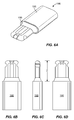
- FIGS. 6A-6D are simplified perspective and plan views of connector 190 with chamfered edges at its base;
- FIG. 7A is a simplified perspective view of a connector jack 400 corresponding to plug connectors 190 while FIG. 7B is a front view of connector jack 400 ;
- FIG. 7C is a bottom plan view of connector jack 400 shown in FIG. 7A while FIG. 7D is a simplified perspective view showing plug connector 190 inserted into connector jack 400 ;
- FIGS. 8A and 8B illustrate the alignment of the contacts of plug connector 190 against that of connector jack 400 when mated according to two different insertion orientations
- FIGS. 9A and 9B are simplified top and front views of connector 500 according to another embodiment of the present invention.
- FIG. 10 is a simplified cross-sectional view of connector 600 according to yet another embodiment of the present invention that is inserted into a corresponding connector jack;
- FIG. 11 illustrates one example of a connector 700 according to another embodiment of the present invention having a fiber optic cable that runs through the center of the connector;
- FIGS. 12 and 13 are simplified top views of connectors according to additional embodiments of the invention.
- Embodiments of the present invention pertain to connectors, such as dual orientation audio connectors with side audio contacts that can be used in place of the standard TRS or TRRS connectors.
- These connectors may be suitable for a multiplicity of electronic devices, including any device with audio out signals (e.g., radio, landline phone, stereo).
- the invention is particularly well suited for portable electronic media devices.
- an electronic media device includes any device with at least one electronic component that may be used to present human-perceivable media.
- Such devices may include, for example, portable music players (e.g., Apple's iPod devices), portable video players (e.g., portable DVD players), cellular telephones (e.g., Apple's iPhone devices), video cameras, digital still cameras, projection systems (e.g., holographic projection systems), gaming systems, PDAs, desktop computers, as well as tablet or other mobile computers (e.g., Apple's iPad devices).
- portable music players e.g., Apple's iPod devices
- portable video players e.g., portable DVD players
- cellular telephones e.g., Apple's iPhone devices
- video cameras digital still cameras
- projection systems e.g., holographic projection systems
- gaming systems e.g., PDAs, desktop computers, as well as tablet or other mobile computers (e.g., Apple's iPad devices).
- Some of these devices may be configured to provide audio, video or
- FIG. 3 is a simplified illustrative block diagram representing an electronic media device 100 that includes an audio plug receptacle 105 according to embodiments of the present invention.
- Electronic media device 100 may also include, among other components, connector receptacle 110 , one or more user input components 120 , one or more output components 125 , control circuitry 130 , graphics circuitry 135 , a bus 140 , a memory 145 , a storage device 150 , communications circuitry 155 and POM (position, orientation or movement sensor) sensors 160 .
- Control circuitry 130 may communicate with the other components of electronic media device 100 (e.g., via bus 140 ) to control the operation of electronic media device 100 .
- control circuitry 130 may execute instructions stored in a memory 145 .
- Control circuitry 130 may also be operative to control the performance of electronic media device 100 .
- Control circuitry 130 may include, for example, a processor, a microcontroller and a bus (e.g., for sending instructions to the other components of electronic media device 100 ).
- control circuitry 130 may also drive the display and process inputs received from input component 120 .
- Memory 145 may include one or more different types of memory that may be used to perform device functions.
- memory 145 may include cache, flash memory, ROM, RAM and hybrid types of memory.
- Memory 145 may also store firmware for the device and its applications (e.g., operating system, user interface functions and processor functions).
- Storage device 150 may include one or more suitable storage mediums or mechanisms, such as a magnetic hard drive, flash drive, tape drive, optical drive, permanent memory (such as ROM), semi-permanent memory (such as RAM) or cache.
- Storage device 150 may be used for storing media (e.g., audio and video files), text, pictures, graphics, advertising or any suitable user-specific or global information that may be used by electronic media device 100 .
- Storage device 150 may also store programs or applications that may run on control circuitry 130 , may maintain files formatted to be read and edited by one or more of the applications and may store any additional files that may aid the operation of one or more applications (e.g., files with metadata). It should be understood that any of the information stored on storage device 150 may instead be stored in memory 145 .
- Electronic media device 100 may also include input component 120 and output component 125 for providing a user with the ability to interact with electronic media device 100 .
- input component 120 and output component 125 may provide an interface for a user to interact with an application running on control circuitry 130 .
- Input component 120 may take a variety of forms, such as a keyboard/keypad, trackpad, mouse, click wheel, button, stylus or touch screen.
- Input component 120 may also include one or more devices for user authentication (e.g., smart card reader, fingerprint reader or iris scanner) as well as an audio input device (e.g., a microphone) or a video input device (e.g., a camera or a web cam) for recording video or still frames.
- Output component 125 may include any suitable display, such as a liquid crystal display (LCD) or a touch screen display, a projection device, a speaker or any other suitable system for presenting information or media to a user. Output component 125 may be controlled by graphics circuitry 135 . Graphics circuitry 135 may include a video card, such as a video card with 2D, 3D or vector graphics capabilities. In some embodiments, output component 125 may also include an audio component that is remotely coupled to electronic media device 100 . For example, output component 125 may include a headset, headphones or ear buds that may be coupled to electronic media device 100 with a wire or wirelessly (e.g., Bluetooth headphones or a Bluetooth headset).
- a headset headphones or ear buds that may be coupled to electronic media device 100 with a wire or wirelessly (e.g., Bluetooth headphones or a Bluetooth headset).
- Electronic media device 100 may have one or more applications (e.g., software applications) stored on storage device 150 or in memory 145 .
- Control circuitry 130 may be configured to execute instructions of the applications from memory 145 .
- control circuitry 130 may be configured to execute a media player application that causes full-motion video or audio to be presented or displayed on output component 125 .
- Other applications resident on electronic media device 100 may include, for example, a telephony application, a GPS navigator application, a web browser application and a calendar or organizer application.
- Electronic media device 100 may also execute any suitable operating system, such as a Mac OS, Apple iOS, Linux or Windows and can include a set of applications stored on storage device 150 or memory 145 that is compatible with the particular operating system.
- electronic media device 100 may also include communications circuitry 155 to connect to one or more communications networks.
- Communications circuitry 155 may be any suitable communications circuitry operative to connect to a communications network and to transmit communications (e.g., voice or data) from electronic media device 100 to other devices within the communications network.
- Communications circuitry 155 may be operative to interface with the communications network using any suitable communications protocol such as, for example, Wi-Fi (e.g., a 802.11 protocol), Bluetooth, high frequency systems (e.g., 900 MHz, 2.4 GHz and 5.6 GHz communication systems), infrared, GSM, GSM plus EDGE, CDMA, quadband and other cellular protocols, VoIP or any other suitable protocol.
- Wi-Fi e.g., a 802.11 protocol
- Bluetooth high frequency systems
- high frequency systems e.g., 900 MHz, 2.4 GHz and 5.6 GHz communication systems
- infrared GSM, GSM plus EDGE, CDMA, quadband and other cellular protocols, VoIP
- communications circuitry 155 may be operative to create a communications network using any suitable communications protocol.
- Communications circuitry 155 may create a short-range communications network using a short-range communications protocol to connect to other devices.
- communications circuitry 155 may be operative to create a local communications network using the Bluetooth protocol to couple with a Bluetooth headset (or any other Bluetooth device).
- Communications circuitry 155 may also include a wired or wireless network interface card (NIC) configured to connect to the Internet or any other public or private network.
- NIC network interface card
- electronic media device 100 may be configured to connect to the Internet via a wireless network, such as a packet radio network, an RF network, a cellular network or any other suitable type of network.
- Communication circuitry 145 may be used to initiate and conduct communications with other communications devices or media devices within a communications network.
- Electronic media device 100 may also include any other component suitable for performing a communications operation.
- electronic media device 100 may include a power supply, an antenna, ports or interfaces for coupling to a host device, a secondary input mechanism (e.g., an ON/OFF switch) or any other suitable component.
- a secondary input mechanism e.g., an ON/OFF switch
- Electronic media device 100 may also include POM sensors 160 .
- POM sensors 160 may be used to determine the approximate geographical or physical location of electronic media device 100 .
- the location of electronic media device 100 may be derived from any suitable trilateration or triangulation technique, in which case POM sensors 160 may include an RF triangulation detector or sensor or any other location circuitry configured to determine the location of electronic media device 100 .
- POM sensors 160 may also include one or more sensors or circuitry for detecting the position orientation or movement of electronic media device 100 .
- sensors and circuitry may include, for example, single-axis or multi-axis accelerometers, angular rate or inertial sensors (e.g., optical gyroscopes, vibrating gyroscopes, gas rate gyroscopes or ring gyroscopes), magnetometers (e.g., scalar or vector magnetometers), ambient light sensors, proximity sensors, motion sensor (e.g., a passive infrared (PIR) sensor, active ultrasonic sensor or active microwave sensor) and linear velocity sensors.
- PIR passive infrared
- control circuitry 130 may be configured to read data from one or more of POM sensors 160 in order to determine the location orientation or velocity of electronic media device 100 .
- POM sensors 160 may be positioned near output component 125 (e.g., above, below or on either side of the display screen of electronic media device 100 ).
- FIG. 4 depicts an illustrative rendering of one particular electronic media device 180 .
- Device 180 includes a click wheel 182 as an input component and an LED display 184 as an output component.
- Device 180 also includes connector receptacle 186 and audio plug receptacle 188 .
- various internal components such as the control circuitry, graphics circuitry, bus, memory, storage device and other components are not shown in FIG. 4 .
- Some embodiments of the invention are directed towards an audio connector and are particularly suitable for mating with receptacle connector 188 .
- Other embodiments of the invention are directed towards data connectors and may be particularly useful for mating with receptacle connector 186 .
- FIGS. 5A and 5B depict various views of a first embodiment of an audio plug connector 190 according to the present invention.
- FIGS. 5A and 5B are simplified top and front views, respectively, of connector 190 according to an embodiment of the present invention.
- connector 190 includes a connector tab or tongue 193 that extends out of and longitudinally away from a body 198 .
- Tab 193 includes two symmetrical and electrically isolated conductive sections 192 a , 192 b around its outer periphery which can function as signal contacts (as opposed to ground or power contacts) in one embodiment.
- contact 192 a is a left audio out contact and contact 192 b is a right audio out contact.
- a microphone contact 192 c is positioned at the distal tip of the connector and ground contacts 192 d , one on each of the two major opposing sides, are positioned between the left and right audio contacts 192 a and 192 b .
- An overmolded dielectric fill 195 separates the electrical contacts and retention features 194 a and 194 b , shown as notches in FIG. 5A , formed on the sides of contacts 192 a , 192 b which can be used as part of a retention mechanism. All the aforementioned elements make up the connector tab, which is connected to body 198 at the base of the connector tab as shown in FIGS. 5A and 5B .
- body 198 may be thicker than the connector tab (e.g., as shown in FIGS. 5A and 5B ), while in other embodiments the tab and body may have substantially the same thickness.
- contacts 192 a - 192 d are external contacts and connector 190 does not include an exposed cavity in which particles and debris may collect.
- connector 190 is fully sealed and includes no moving parts.
- connector 190 has a considerably reduced insertion depth as compared to commonly available TRS and TRRS connectors described above.
- the connector tab of connector 190 has a width, X, of about 4.1 mm; a thickness, Y, of about 1.5 mm; and an insertion depth, Z, of about 5.5 mm.
- the connector tab of connector 190 has a width, X, of about 4.1 mm; a thickness, Y, of about 1.5 mm; and an insertion depth, Z, of about 5.75 mm.
- Contacts 192 a - 192 d can be made from a copper, nickel, brass, a metal alloy or any other appropriate conductive material. Contacts 192 a - 192 d are spaced and tab 193 is shaped so as to provide 180 degree symmetry so that plug connector 190 can be inserted into a corresponding receptacle connector (shown in FIGS. 7A-7D ) in either of two orientations as discussed below. In some embodiments, contacts 192 a and 192 b may be a fraction of their relative sizes shown in FIG. 5A , while still positioned so as to provide 180 degree symmetry for plug connector 190 (e.g., contacts 192 a and 192 b as shown in FIG. 5D ).
- contacts 192 a and 192 b may be formed to include and surround a small region about retention features 194 a and 194 b and are positioned so as to provide 180 degree symmetry for plug connector 190 (e.g., contacts 192 a and 192 b as shown in FIG. 5C ).
- each of contacts 192 a - 192 d is in electrical contact with a corresponding contact in the receptacle connector.
- Connector 190 has a 180 degree symmetrical, dual orientation design which enables the connector to be inserted into a connector jack with either of the two major opposing sides on top.
- the two audio contacts 192 a and 192 b are located on opposite sides of the connector. In this manner, an audio contact is always on the right and left side of the connector, microphone contact 192 c is always positioned at the distal tip of the connector, and ground contacts 192 d , one on each of the two major opposing sides, are always in the same position regardless of the orientation.
- a sensing circuit in the receptacle connector or the electronic device in which the receptacle connector is housed may detect the orientation of connector 190 and switch internal connections to the contacts corresponding to contacts 192 a and 192 b in the connector jack as described below with respect to FIGS. 8A and 8B .
- Two retention features 194 a and 194 b are formed in contacts 192 a and 192 b , respectively, and located on opposing sides of the connector tab near its distal end.
- connector 190 is inserted into a receptacle connector (shown in FIG. 7A ) until retention features 194 a and 194 b , e.g., notches, operatively engage with a retention mechanism, such as a cantilevered spring or detent as described with respect to FIGS. 7A-7D .
- a retention mechanism such as a cantilevered spring or detent as described with respect to FIGS. 7A-7D .
- the depth and position of retention features 194 a and 194 b are selected to provide specific insertion and extraction forces such that the retention force required to insert connector 190 into a connector jack (shown in FIG. 7A ) is higher than the extraction force required to remove the connector from the connector jack.
- the inventors have determined that positioning the retention features 194 a and 194 b and corresponding latching mechanism (shown in FIGS. 7B-7D ) near the distal end of connector 190 helps to better secure the connector 190 sideways when it is in an engaged position within a connector jack (shown in FIG. 7C ).
- the retention features or notches may be located on the distal third of the connector tab.
- other retention mechanisms can be used such as mechanical or magnetic latches or orthogonal insertion mechanisms, which may or may not require the presence of retention features 194 a and 194 b (e.g., notches).
- FIGS. 6A-6D are simplified perspective and plan views of connector 190 with chamfered edges at its base.
- Chamfered edge 199 connects body 195 to the tab portion of connector 190 .
- Body 195 may also be stiffened to increase its strength in a side-load condition.
- body 195 may have a thicker base portion underneath its outer surface.
- each of contacts 192 a , 192 b and 192 d shown in FIG. 6A may have a reduced length as compared to how they are shown in FIG. 5A .
- FIG. 7A is a simplified perspective view of a receptacle connector 400 that can be used in conjunction with certain plug connectors of the present invention
- FIG. 7B is a front view of receptacle connector 400
- Connector jack 400 includes a housing 402 that defines an interior cavity 404 into which connector 190 can be inserted. Also shown in FIG. 7A are contacts 406 d that may be electrically coupled to ground contacts 192 d (shown in FIG. 5A ) regardless of the insertion orientation of connector 190 .
- Contacts 406 a - 406 b are also present at the sides of cavity 404 and correspond to plug connector contacts 192 a - 192 b , respectively, while a contact 406 c is present at the back of cavity 400 and positioned to couple to contact 192 c .
- Connector jack 400 is designed to be waterproof so as to not allow ingress of moisture into whatever electronic device the connector is housed within.
- FIG. 7C which is a bottom plan view of connector jack 400
- retention mechanism 408 includes a spring 410 positioned in a cut-out section 412 of housing 402 .
- Spring 410 is pre-loaded so that tip 414 extends through an opening between cut-out section 412 and cavity 404 .
- a second retention mechanism 408 can also be positioned within housing 402 so that there is a retention mechanism 408 on the left and right side of connector 190 (tip 414 of both retention mechanisms 408 are shown in FIG. 7B ).
- retention features 194 a , 194 b are located near the distal end of connectors 190 to better secure the connector sideways when it is in an engaged position within connector jack 400 .
- the rounded bulbous shape of retention features 194 a , 194 b may match the rounded shape of tip 414 of spring 410 to provide a comfortable click feel when the spring engages with the retention features.
- FIGS. 8A-8B illustrate the alignment of the contacts of plug connector 190 against that of connector jack 400 when mated according to both insertion orientations.
- connector 190 has two symmetrical and electrically isolated halves which may function as left and right audio contacts 192 a , 192 b .
- a microphone contact 192 c is positioned at the distal tip of the connector and ground contacts 192 d , one on each of the two major opposing sides, are positioned between the left and right audio contacts.
- connector jack 400 detects the orientation of connector 190 (orientations shown in FIG. 8A and FIG.
- a software switch can be used to switch the connector jack's left and right audio contacts depending on the insertion orientation or a hardware switch can be used to switch the left and right audio contacts of the connector jack to match the contacts of connector 190 .
- This may be implemented for use with either corresponding connector 190 .
- a software switch can be used to switch the receptacle jack's contacts for left and right audio depending on the insertion orientation while a hardware switch can be used to switch the connector jacks microphone and ground contacts to match the contacts of connector 190 .
- the host device flips the signals to correspond to the second possible orientation (i.e., flips the signals 180 degrees) and repeats the Acknowledgement/Response signal routine.
- a physical orientation key e.g., a unique notch or other physical features
- a hardware or software switch can set the receptacle connector contacts as appropriate for left and right audio or other data contacts to correspond to the plug connector contacts.
- FIGS. 9A and 9B are simplified top and front views, respectively, of another embodiment of a dual-orientation connector according to the present invention. As shown in FIGS. 9A and 9B , the entirety of dual-orientation connector 500 is substantially flat. That is, body 505 of the connector has the same thickness and width as the connector tab of connector 500 .
- connector 600 is similar to connector 190 (shown in FIG. 5A ) except for the differences discussed above. Accordingly, connector 600 includes a dielectric body and other contacts as found in connector 190 .
- Lens 710 can be made from a chemically strengthened aluminosilicate glass or a similar material that is highly resistant to scratching and is flush with the external surface of connector 710 (as shown in FIG. 11 ) to prevent debris build-up and abstraction of light.
- FIG. 12 illustrates a connector 800 according to another embodiment of the invention that includes contacts 192 e and 192 f on each side of ground contact 192 d , along with similarly positioned contacts 192 g and 192 h on each side of the opposite side ground contact.
- connector 800 includes a total of seven signal contacts in addition to the two ground contacts.
- the extra four contacts 192 e - 192 f can be two pairs of differential data contacts for high speed data transfer.
- the extra four contacts can be used for video signals.
- the invention also includes many other signal transfer variations of the embodiments previously mentioned which may be accomplish by similar modifications.
- FIG. 13 shows a plug connector 810 that includes twice the number of signal contacts as connector 800 by doubling the number of contacts along the length of the connector. That is, additional insulation separates contacts that are spaced apart from each other along the length of the connector just as insulation separates contacts spaced apart along the width of the connector.
Landscapes
- Physics & Mathematics (AREA)
- General Physics & Mathematics (AREA)
- Optics & Photonics (AREA)
- Details Of Connecting Devices For Male And Female Coupling (AREA)
- Coupling Device And Connection With Printed Circuit (AREA)
Priority Applications (1)
| Application Number | Priority Date | Filing Date | Title |
|---|---|---|---|
| US13/704,236 US8931962B2 (en) | 2010-06-18 | 2011-06-20 | Dual orientation connector with side contacts |
Applications Claiming Priority (3)
| Application Number | Priority Date | Filing Date | Title |
|---|---|---|---|
| US35649910P | 2010-06-18 | 2010-06-18 | |
| US13/704,236 US8931962B2 (en) | 2010-06-18 | 2011-06-20 | Dual orientation connector with side contacts |
| PCT/US2011/041127 WO2011160138A2 (en) | 2010-06-18 | 2011-06-20 | Dual orientation connector with side contacts |
Publications (2)
| Publication Number | Publication Date |
|---|---|
| US20130089291A1 US20130089291A1 (en) | 2013-04-11 |
| US8931962B2 true US8931962B2 (en) | 2015-01-13 |
Family
ID=45348932
Family Applications (1)
| Application Number | Title | Priority Date | Filing Date |
|---|---|---|---|
| US13/704,236 Expired - Fee Related US8931962B2 (en) | 2010-06-18 | 2011-06-20 | Dual orientation connector with side contacts |
Country Status (5)
| Country | Link |
|---|---|
| US (1) | US8931962B2 (de) |
| EP (1) | EP2583356A4 (de) |
| KR (1) | KR20130031893A (de) |
| CN (1) | CN103069654A (de) |
| WO (1) | WO2011160138A2 (de) |
Cited By (11)
| Publication number | Priority date | Publication date | Assignee | Title |
|---|---|---|---|---|
| US20150155657A1 (en) * | 2010-05-28 | 2015-06-04 | Apple Inc. | Dual orientation connector with external contacts |
| US9054477B2 (en) | 2012-09-11 | 2015-06-09 | Apple Inc. | Connectors and methods for manufacturing connectors |
| US9059531B2 (en) | 2012-09-11 | 2015-06-16 | Apple Inc. | Connectors and methods for manufacturing connectors |
| US9093803B2 (en) | 2012-09-07 | 2015-07-28 | Apple Inc. | Plug connector |
| US9106031B2 (en) | 2011-11-07 | 2015-08-11 | Apple Inc. | Dual orientation electronic connector |
| US9112327B2 (en) | 2011-11-30 | 2015-08-18 | Apple Inc. | Audio/video connector for an electronic device |
| US9160129B2 (en) | 2012-09-11 | 2015-10-13 | Apple Inc. | Connectors and methods for manufacturing connectors |
| US9325097B2 (en) | 2012-11-16 | 2016-04-26 | Apple Inc. | Connector contacts with thermally conductive polymer |
| US9350125B2 (en) | 2013-01-24 | 2016-05-24 | Apple Inc. | Reversible USB connector with compliant member to spread stress and increase contact normal force |
| DE102015001637A1 (de) | 2015-02-07 | 2016-08-25 | Gorilla Electronics GmbH | Elektrischer Steck-Verbinder und elektronischer Schlüssel und Verfahren zur besitzbasierenden Authentifizierung mit schaltbaren Authentifizierungs-Sicherheitsstufen und zuschaltbarer wissenbasierter oder eigenschaftbasierter Authentifizierung zur Authentifizierung einer Aktion, einer Person oder einer über den Steckverbinder erfolgenden Datenübertragung |
| US10909060B2 (en) | 2018-12-11 | 2021-02-02 | Ati Technologies Ulc | Data transmission using flippable cable |
Families Citing this family (31)
| Publication number | Priority date | Publication date | Assignee | Title |
|---|---|---|---|---|
| US7589536B2 (en) | 2007-01-05 | 2009-09-15 | Apple Inc. | Systems and methods for determining the configuration of electronic connections |
| US8882524B2 (en) * | 2010-06-21 | 2014-11-11 | Apple Inc. | External contact plug connector |
| CN103004035A (zh) * | 2010-06-21 | 2013-03-27 | 苹果公司 | 外部接触插塞连接器 |
| US9293876B2 (en) | 2011-11-07 | 2016-03-22 | Apple Inc. | Techniques for configuring contacts of a connector |
| USD960106S1 (en) | 2012-07-06 | 2022-08-09 | Apple Inc. | Connector |
| USD684539S1 (en) | 2012-07-06 | 2013-06-18 | Apple Inc. | Connector |
| USD731434S1 (en) | 2012-07-06 | 2015-06-09 | Apple Inc. | Connector |
| USD684976S1 (en) | 2012-09-07 | 2013-06-25 | Jody Akana | Adapter |
| US8777666B2 (en) | 2012-09-07 | 2014-07-15 | Apple Inc. | Plug connector modules |
| USD699188S1 (en) | 2012-09-11 | 2014-02-11 | Apple Inc. | Adapter |
| US8804353B2 (en) | 2012-09-11 | 2014-08-12 | Apple Inc. | Trim for input/output architecture in an electronic device |
| US8804355B2 (en) * | 2012-09-11 | 2014-08-12 | Apple Inc. | Connector bracket |
| US8804354B2 (en) | 2012-09-11 | 2014-08-12 | Apple Inc. | Load sharing device and I/O architecture against imparted abuse loads |
| USD781785S1 (en) | 2012-09-11 | 2017-03-21 | Apple Inc. | Adapter |
| USD716234S1 (en) * | 2013-04-03 | 2014-10-28 | Hon Hai Precision Industry Co., Ltd. | Electrical adapter |
| TWM504381U (zh) * | 2013-05-09 | 2015-07-01 | Foxconn Interconnect Technology Ltd | 電連接器 |
| US9490579B2 (en) | 2013-07-19 | 2016-11-08 | Foxconn Interconnect Technology Limited | Flippable Electrical Connector |
| US9578401B2 (en) * | 2013-07-24 | 2017-02-21 | Commscope Technologies Llc | Systems and methods for detecting component rotation within a communication assembly |
| CN203826627U (zh) * | 2014-05-14 | 2014-09-10 | 杭州纳雄科技有限公司 | 一种音频插座机构 |
| US9709757B2 (en) * | 2014-10-17 | 2017-07-18 | Commscope Technologies Llc | Systems and methods for port mapping |
| GB2553875B (en) | 2015-02-25 | 2018-09-05 | Cirrus Logic Int Semiconductor Ltd | Connectors for audio data transfer |
| USD826157S1 (en) | 2015-12-16 | 2018-08-21 | Futurewei Technologies, Inc. | Combined audio jack and plug |
| EP3349151B1 (de) * | 2017-01-11 | 2019-11-06 | Mohammad Khaled Asef | Doppelseitiger taster mit touchfunktion |
| US10931072B2 (en) | 2017-01-23 | 2021-02-23 | Sony Corporation | Transmitting device, reception device, and optical-electrical composite cable |
| US10904032B2 (en) * | 2018-05-15 | 2021-01-26 | The Boeing Company | Multi-use optical data, powerline data, and ground power interface for an airplane |
| US12504586B2 (en) * | 2018-08-03 | 2025-12-23 | Ppc Broadband, Inc. | Fiber optical connectors |
| US11047925B2 (en) * | 2018-11-29 | 2021-06-29 | Sony Interactive Entertainment Inc. | Split ground connector |
| US11435534B2 (en) * | 2019-06-11 | 2022-09-06 | Clearfield, Inc. | Flexible optical fiber connectors and assemblies |
| CN112440778A (zh) * | 2019-08-29 | 2021-03-05 | 深圳市瑞能实业股份有限公司 | 一种充电枪和充电系统 |
| USD1078658S1 (en) * | 2023-06-04 | 2025-06-10 | Apple Inc. | Cable |
| TWI877757B (zh) * | 2023-08-31 | 2025-03-21 | 大陸商美律電子(深圳)有限公司 | 音訊裝置及其控制方法 |
Citations (153)
| Publication number | Priority date | Publication date | Assignee | Title |
|---|---|---|---|---|
| US2792557A (en) | 1954-11-10 | 1957-05-14 | Dowick Benjamin | Heavy duty electric adapters for two and three wire systems |
| US2892990A (en) * | 1953-10-19 | 1959-06-30 | Land Air Inc | Electrical connector |
| US3760335A (en) | 1971-05-27 | 1973-09-18 | Amp Inc | Pre-loaded electric connector |
| US3793614A (en) | 1971-08-02 | 1974-02-19 | Gen Electric | Elastomeric shield for an electrical conductor connector module and method of making same |
| US3795037A (en) | 1970-05-05 | 1974-03-05 | Int Computers Ltd | Electrical connector devices |
| US4361375A (en) | 1980-09-15 | 1982-11-30 | Switchcraft, Inc. | Miniature audio connector |
| EP0081372A3 (de) | 1981-12-07 | 1984-07-18 | RAYCHEM CORPORATION (a California corporation) | Verbindungsvorrichtung |
| US4558912A (en) | 1983-12-14 | 1985-12-17 | Amp Incorporated | Edge connector for chip carrier |
| US4621882A (en) | 1984-05-14 | 1986-11-11 | Beta Phase, Inc. | Thermally responsive electrical connector |
| US4711506A (en) | 1985-05-28 | 1987-12-08 | Hosiden Electronics Co., Ltd. | Socket of electrostatic protection type |
| JPH0278171A (ja) | 1988-09-13 | 1990-03-19 | Fujitsu Ltd | 雄コネクタ |
| US5040994A (en) | 1988-12-23 | 1991-08-20 | Sanyo Electric Co., Ltd. | Connector structure for hybrid integrated circuit |
| US5256074A (en) | 1992-05-20 | 1993-10-26 | Foxconn International, Inc. | Connector having improved electrostatic discharge protection |
| US5295843A (en) | 1993-01-19 | 1994-03-22 | The Whitaker Corporation | Electrical connector for power and signal contacts |
| US5380225A (en) | 1992-07-24 | 1995-01-10 | Minnesota Mining And Manufacturing Company | Electrical connector |
| US5387110A (en) | 1993-11-12 | 1995-02-07 | International Business Machines Corporation | Reversible dual media adapter cable |
| US5442243A (en) | 1993-02-16 | 1995-08-15 | Electro Lock, Inc. | Electrical key and lock system |
| US5554042A (en) | 1995-02-28 | 1996-09-10 | Trimble Navigation, Limited | Resilient body electrical connector system |
| US5594284A (en) | 1994-10-06 | 1997-01-14 | George Hill | Vehicle security device using key device which completes interrupted circuits |
| DE19609571A1 (de) | 1995-11-20 | 1997-05-22 | Sihn Jr Kg Wilhelm | Koaxialer Steckverbinder für die Kommunikationstechnik in Automobilen |
| US5959848A (en) | 1997-03-17 | 1999-09-28 | Astec International Limited | Low inductance high current connector for improved power supply system |
| US5967833A (en) | 1996-08-20 | 1999-10-19 | North American Specialties Corporation | Circuit connector with multiple contacts and built in strain relief |
| US6074225A (en) | 1999-04-13 | 2000-06-13 | Hon Hai Precision Ind. Co., Ltd. | Electrical connector for input/output port connections |
| US6086421A (en) | 1998-07-14 | 2000-07-11 | Hon Hai Precision Inc. Co., Ltd. | Electrical connector with one-piece shield |
| US6113427A (en) | 1998-10-30 | 2000-09-05 | Hon Hai Precision Ind. Co., Ltd. | Electrical connector having improved shielding structure |
| US6179627B1 (en) | 1998-04-22 | 2001-01-30 | Stratos Lightwave, Inc. | High speed interface converter module |
| US6231396B1 (en) | 1999-12-29 | 2001-05-15 | Hon Hai Precision Ind. Co., Ltd. | Jack connector |
| US6322394B1 (en) | 1999-03-04 | 2001-11-27 | Fujitsu Takamisawa Component Limited | Electrical connector having a fixing mechanism and method for manufacturing said electrical connector |
| US20010046809A1 (en) | 2000-05-24 | 2001-11-29 | Kiyohiko Chiran | Receptacle type intermediate connector |
| US6364699B1 (en) | 2000-05-18 | 2002-04-02 | Hon Hai Precision Ind. Co., Ltd. | Cable connector assembly device with improved latching means |
| US6410857B1 (en) | 2001-03-01 | 2002-06-25 | Lockheed Martin Corporation | Signal cross-over interconnect for a double-sided circuit card assembly |
| US6482045B2 (en) | 1998-09-11 | 2002-11-19 | Hosiden Corporation | Connector socket, connector plug and connector assembly |
| US20030016509A1 (en) | 2001-07-18 | 2003-01-23 | Masashi Tsukamoto | Flat circuit device and method of manufacturing |
| CN1397804A (zh) | 2001-07-18 | 2003-02-19 | 株式会社鼎新 | 具有接触块的接触结构 |
| US6530793B2 (en) | 1999-08-24 | 2003-03-11 | Braun Gmbh | Multipole connector assembly for low-voltage appliances |
| JP2003217728A (ja) | 2002-01-22 | 2003-07-31 | Fujitsu Ltd | Usbコネクタ |
| US20030207606A1 (en) | 2001-02-22 | 2003-11-06 | Ho Su Yueh | Locking and releasable electrical receptacle/connector |
| US6692311B1 (en) | 1999-10-25 | 2004-02-17 | Omron Corporation | Sensor system and connector used therefor |
| JP2004079491A (ja) | 2002-08-14 | 2004-03-11 | Hiroshi Akutsu | プラグとレセプタクルの接続 |
| US6786763B2 (en) | 2003-01-28 | 2004-09-07 | Hon Hai Precision Ind. Co., Ltd. | Cable end connector assembly having relatively simple structure and improved terminal structure |
| WO2004097995A1 (de) | 2003-05-02 | 2004-11-11 | Hirdes Ruediger | Elektrische steckkupplung |
| US20040229515A1 (en) | 2003-02-07 | 2004-11-18 | Atsushi Kaneda | Plug attaching mechanism |
| US6846202B1 (en) | 1999-08-20 | 2005-01-25 | Tyco Electronics Logistics Ag | Electrical connector assembly with moveable contact elements |
| WO2005013436A1 (en) | 2003-07-28 | 2005-02-10 | Sandisk Secure Content Solutions, Inc. | Electrical connector |
| US6869320B2 (en) | 2003-04-23 | 2005-03-22 | Hewlett-Packard Development Company, L.P. | Portable modular electronic system with symmetrical connections |
| US20050079738A1 (en) | 2003-09-01 | 2005-04-14 | Sts Semiconductor And Telecommunications Co., Ltd. | USB storage device including USB plug with top and bottom terminals |
| US20050085136A1 (en) | 2003-10-17 | 2005-04-21 | Hongbo Zhang | Electrical connector having reliable contacts |
| US6902432B2 (en) | 2002-02-21 | 2005-06-07 | Yazaki Corporation | USB connector |
| US20050124219A1 (en) | 2003-12-06 | 2005-06-09 | Wei-Xing Chen | Power connector with improved contact structure |
| US20050124217A1 (en) | 2003-12-06 | 2005-06-09 | Quan Zhuang | Electrical connector |
| US20050124218A1 (en) | 2003-12-03 | 2005-06-09 | Wei-Xing Chen | Electrical connector |
| US20050202727A1 (en) | 2004-03-12 | 2005-09-15 | Apple Computer, Inc., A California Corporation | DC connector assembly |
| US6948965B2 (en) | 2004-02-13 | 2005-09-27 | Fujitsu Component Limited | Balanced transmission cable connector |
| US6948983B1 (en) | 2004-08-10 | 2005-09-27 | Megaforce Company Limited | Slim USB male connector with anti-disorientation design |
| US6962510B1 (en) | 2004-08-05 | 2005-11-08 | Hon Hai Precision Ind. Co., Ltd. | Electrical connector having improved structure regarding terminals |
| WO2005124932A2 (en) | 2004-06-17 | 2005-12-29 | Walletex Microelectronics Ltd. | Improved connector and device for flexibly connectable computer systems |
| US6981887B1 (en) | 2004-08-26 | 2006-01-03 | Lenovo (Singapore) Pte. Ltd. | Universal fit USB connector |
| US20060019545A1 (en) | 2004-07-26 | 2006-01-26 | Fujitsu Component Limited | Connector unit for differential transmission |
| US20060024997A1 (en) | 2004-08-02 | 2006-02-02 | M-Systems Flash Disk Pioneers Ltd. | Reversible universal serial bus (USB) device and connector |
| US20060040549A1 (en) | 2004-08-18 | 2006-02-23 | Li-Ho Yao | Usb plug with two sides alternately connectable to a usb port |
| US7021971B2 (en) | 2003-09-11 | 2006-04-04 | Super Talent Electronics, Inc. | Dual-personality extended-USB plug and receptacle with PCI-Express or Serial-At-Attachment extensions |
| US20060148300A1 (en) | 2004-06-18 | 2006-07-06 | Advanced Connectek Inc. | USB connector with latching arrangement |
| US7074052B1 (en) | 2005-05-11 | 2006-07-11 | Super Talent Electronics, Inc. | USB device with case having integrated plug shell |
| WO2006074348A1 (en) | 2005-01-07 | 2006-07-13 | Apple Inc. | Universal serial bus connector and socket coupling arrangements |
| EP1684391A2 (de) | 2005-01-20 | 2006-07-26 | Kabushiki Kaisha Tokai-Rika-Denki-Seisakusho | Herstellungsverfahren eines Verbindungsendstückes und Verbindungsendstück |
| US20060216991A1 (en) | 2005-03-23 | 2006-09-28 | Boutros Kamal S | Electrical connector with positive lock |
| EP1717910A2 (de) | 2005-04-27 | 2006-11-02 | LG Electronics, Inc. | Mobiles Kommunikationsendgerät mit Multifunktionsanschlussdose und entsprechendes Verfahren |
| US20060289201A1 (en) | 2005-06-22 | 2006-12-28 | Gi-Cherl Kim | Backlight assembly, display device having the same, and method thereof |
| US7175444B2 (en) | 2005-02-23 | 2007-02-13 | Molex Incorporated | Plug connector and construction therefor |
| US20070037452A1 (en) * | 2005-08-09 | 2007-02-15 | Tyco Electronics Corporation | Electrical connector adapter and method for making |
| US20070049100A1 (en) | 2005-08-26 | 2007-03-01 | Advanced Connectek Inc. | Electrical connector with a spring push button for disengagement with jack |
| US20070072442A1 (en) | 2005-09-26 | 2007-03-29 | Apple Computer, Inc. | Electromagnetic connector for electronic device |
| US7198522B1 (en) | 2006-10-24 | 2007-04-03 | Cheng Uei Precision Industry Co., Ltd. | Plug connector |
| US20070082701A1 (en) | 2005-10-11 | 2007-04-12 | Belkin Corporation | System for interfacing with an audio player, and method of manufacturing same |
| US7249978B1 (en) | 2005-10-24 | 2007-07-31 | Super Talent Electronics, Inc. | Reduced-length, low-profile USB device and card-like carrier |
| US20070178771A1 (en) | 2006-01-27 | 2007-08-02 | David Robert Goetz | Releasable plug connector system |
| DE202004021354U1 (de) | 2003-08-11 | 2007-09-06 | Hirschmann Electronics Gmbh & Co. Kg | Elastische Kontaktelemente |
| TWM318831U (en) | 2007-02-16 | 2007-09-11 | Inventec Appliances Corp | Universal series bus structure |
| US20070243726A1 (en) | 2006-04-14 | 2007-10-18 | Trenne Rodney J | Reversible universal serial bus connection interface for USB connectors and universal serial bus ports |
| US20080032562A1 (en) | 2006-07-24 | 2008-02-07 | Hon Hai Precision Ind. Co., Ltd. | Miniature audio jack connector |
| US20080067248A1 (en) | 2005-04-21 | 2008-03-20 | Super Talent Electronics, Inc. | Extended USB Dual-Personality Card Reader |
| US20080090465A1 (en) | 2006-09-08 | 2008-04-17 | Sony Corporation | Plug |
| US7364445B1 (en) | 2007-04-13 | 2008-04-29 | Super Talent Electronics, Inc. | USB flash device with rubber cover |
| US20080119291A1 (en) | 2006-11-17 | 2008-05-22 | Nintendo Co., Ltd. | Secure and/or lockable connecting arrangement for video game system |
| US20080119076A1 (en) | 2006-11-22 | 2008-05-22 | Sandisk Il Ltd. | Systems of reliably interconnectable reversible usb connectors |
| WO2008065659A2 (en) | 2006-11-29 | 2008-06-05 | Walletex Microelectronics Ltd. | Male data communication connector having contacts of different height |
| US7396257B2 (en) | 2005-05-26 | 2008-07-08 | Itt Manufacturing Enterprises, Inc. | Computer input/output (I/O) connector assembly having a security circuit disposed therein |
| US20080167828A1 (en) * | 2007-01-05 | 2008-07-10 | Terlizzi Jeffrey J | Systems and methods for determining the configuration of electronic connections |
| US7407416B1 (en) | 2006-09-27 | 2008-08-05 | Sprint Communications Company L.P. | Multi-stage multi-pole connector |
| US7435107B2 (en) | 2006-02-20 | 2008-10-14 | Japan Aviation Electronics Industry, Limited | Electrical connector with signal paired contacts and ground contacts arranged to minimize occurance of crosstalk |
| US7442091B2 (en) | 2006-12-07 | 2008-10-28 | Sandisk Il Ltd. | Back-to-back PCB double-sided USB connector |
| US20080309313A1 (en) | 2007-06-15 | 2008-12-18 | Apple Inc. | Systems and methods for providing device-to-device handshaking through a power supply signal |
| US20090004923A1 (en) | 2007-06-28 | 2009-01-01 | Apple Inc. | Apparatus and methods for connecting two electrical devices together |
| TWM350153U (de) | 2008-08-22 | 2009-02-01 | Taiwin Electronics Co Ltd | |
| US20090108848A1 (en) | 2007-10-31 | 2009-04-30 | Sony Ericsson Mobile Communications Ab | Additional pins on a usb connector |
| US20090117768A1 (en) | 2007-11-05 | 2009-05-07 | Sheng-Hsin Liao | Adapter having connecting arms |
| WO2009069969A2 (en) | 2007-11-30 | 2009-06-04 | Moon Key Lee | A type symmetric usb receptacle |
| US20090156027A1 (en) | 2007-11-16 | 2009-06-18 | Wan-Tien Chen | Electrical Connector |
| US7549896B2 (en) | 2007-06-13 | 2009-06-23 | Hon Hai Precision Ind. Co., Ltd. | Low profile receptacle connector straddle-mounted on the PCB |
| US7559805B1 (en) | 2008-06-24 | 2009-07-14 | Hon Hai Precision Ind. Co., Ltd. | Electrical connector with power contacts |
| US20090180243A1 (en) | 2008-01-13 | 2009-07-16 | Apple Inc. | Connector assembly |
| WO2009140992A1 (en) | 2008-05-23 | 2009-11-26 | Sony Ericsson Mobile Communications Ab | Connector |
| US20100009575A1 (en) | 2008-07-14 | 2010-01-14 | Apple Inc. | Audio plug with cosmetic hard shell |
| CN201402871Y (zh) | 2009-04-24 | 2010-02-10 | 北京爱国者存储科技有限责任公司 | 一种电连接器的插头和带有该连接器插头的移动存储装置 |
| US20100062656A1 (en) * | 2008-09-05 | 2010-03-11 | Apple Inc. | Low Profile Plug Receptacle |
| EP2169774A1 (de) | 2008-09-30 | 2010-03-31 | Apple Inc. | Mehrstiftsteckverbinder mit reduzierter Größe |
| US7695318B1 (en) | 2008-12-09 | 2010-04-13 | Advanced Connectek Inc. | Plug connector |
| US20100104126A1 (en) | 2008-10-24 | 2010-04-29 | Andrea Martina Greene | Tangle resistant audio cord and earphones |
| US7716400B2 (en) | 2006-05-14 | 2010-05-11 | Sandisk Il Ltd. | Dual mode digital multimedia connector |
| US7717717B1 (en) | 2009-06-26 | 2010-05-18 | Joseph Lai | User-friendly USB connector |
| US7727027B2 (en) | 2008-10-08 | 2010-06-01 | Taiwin Electronics Co., Ltd. | Dual-purpose socket |
| US7740498B1 (en) | 2002-06-07 | 2010-06-22 | Seagate Technology Llc | Advanced backward compatible connector assembly for electrically connecting computer subsystems |
| US20100171465A1 (en) | 2005-06-08 | 2010-07-08 | Belkin International, Inc. | Charging Station Configured To Provide Electrical Power to Electronic Devices And Method Therefor |
| CN101783466A (zh) | 2009-01-21 | 2010-07-21 | 北京爱国者存储科技有限责任公司 | 一种eSATA插座 |
| CN201533091U (zh) | 2009-09-29 | 2010-07-21 | 北京爱国者存储科技有限责任公司 | 一种三合一的插座 |
| US20100221936A1 (en) | 2008-02-26 | 2010-09-02 | Huawei Device Co., Ltd. | USB connector and USB device |
| US20100248544A1 (en) | 2009-03-26 | 2010-09-30 | Hon Hai Precision Industry Co., Ltd. | Cable assembly wth emi protection |
| US20100254662A1 (en) | 2009-04-02 | 2010-10-07 | Hon Hai Precision Industry Co., Ltd. | Connector with improved contacts |
| US20100254602A1 (en) | 2009-04-07 | 2010-10-07 | Dai Nippon Printing Co., Ltd. | Image processing apparatus and method and a computer-readable recording medium on which an image processing program is stored |
| US20100267262A1 (en) | 2009-04-20 | 2010-10-21 | Hon Hai Precision Industry Co., Ltd. | Electrical connector featured with usb/esata interfaces |
| US20100267261A1 (en) | 2009-04-20 | 2010-10-21 | Hon Hai Precision Industry Co., Ltd. | Usb/esata combo receptable featured with ground layer retarding interfaces therebetween |
| US7841894B2 (en) | 2008-04-28 | 2010-11-30 | Hon Hai Precision Ind. Co., Ltd. | Stacked electronical connector |
| US7872873B2 (en) | 2003-12-02 | 2011-01-18 | Super Talent Electronics, Inc. | Extended COB-USB with dual-personality contacts |
| US7892014B2 (en) | 2007-04-04 | 2011-02-22 | John Mezzalingua Associates, Inc. | Releasably engaging high definition multimedia interface plug |
| US7918685B1 (en) | 2010-04-01 | 2011-04-05 | CableJive LLC | Cable assembly for mobile media devices |
| WO2011043488A1 (en) | 2009-10-05 | 2011-04-14 | Yazaki Corporation | Connector |
| US20110136381A1 (en) | 2008-05-19 | 2011-06-09 | Clear Electronics, Inc | Bidirectional plug having short circuit prevention circuit |
| US20110159719A1 (en) | 2009-12-24 | 2011-06-30 | Fujitsu Component Limited | Flat-cable connector, production process thereof, and locking device |
| US20110201213A1 (en) | 2010-02-18 | 2011-08-18 | Apple Inc. | Low profile connector system |
| US8007309B2 (en) | 2009-07-09 | 2011-08-30 | Hon Hai Precision Industry Co., Ltd. | Swayable electronic connector with aligning structure and electronic apparatus employing the same |
| EP2373131A1 (de) | 2010-03-31 | 2011-10-05 | Hosiden Corporation | Steckverbinder und Leiterplattenfußstruktur für einen Verbinder |
| US20110250786A1 (en) | 2010-04-07 | 2011-10-13 | Apple Inc. | Extensible memory card-compatible receptacle and port expansion device |
| US8062073B1 (en) | 2010-09-02 | 2011-11-22 | Tyco Electronics Corporation | Receptacle connector |
| WO2011150403A1 (en) | 2010-05-28 | 2011-12-01 | Zenith Investments Llc | Dual orientation connector with external contacts |
| US20110294354A1 (en) | 2010-05-25 | 2011-12-01 | I/O Interconnect, Ltd. | Usb port, usb plug, and connection structure thereof |
| US20110312200A1 (en) | 2010-06-21 | 2011-12-22 | Hon Hai Precision Industry Co., Ltd. | Electrical connector adapted for plural different mating connectors |
| WO2011163256A1 (en) | 2010-06-21 | 2011-12-29 | Zenith Investments Llc | External contact plug connector |
| US20120028495A1 (en) | 2010-07-30 | 2012-02-02 | Hon Hai Precision Industry Co., Ltd. | Cable assembly |
| US8162696B2 (en) | 2001-09-24 | 2012-04-24 | Gemalto Sa | Dongle which is intended to be connected to a port of a telecommunications device |
| US8277258B1 (en) | 2011-03-11 | 2012-10-02 | Cheng Uei Precision Industry Co., Ltd. | Electrical connector |
| US8282417B2 (en) | 2009-11-20 | 2012-10-09 | Hon Hai Precision Ind. Co., Ltd. | Electrical connector with cooperating upper and lower shield wings |
| US8287299B2 (en) | 2010-10-13 | 2012-10-16 | All Systems Broadband, Inc. | HDMI plug and cable assembly with improved retention features |
| US20130078869A1 (en) | 2010-05-28 | 2013-03-28 | Apple Inc. | D-shaped connector |
| US20130095701A1 (en) | 2010-06-21 | 2013-04-18 | Apple Inc. | External contact plug connector |
| US20130115821A1 (en) | 2011-11-07 | 2013-05-09 | Apple Inc | Dual orientation connector with external contacts and conductive frame |
| WO2013082175A2 (en) | 2011-11-30 | 2013-06-06 | Apple Inc. | Audio/video connector for an electronic device |
| US8545269B2 (en) | 2010-08-13 | 2013-10-01 | Acrox Technology Corporation LTD. | USB wireless connection port for keyboard, mouse and presenter |
| US8561879B2 (en) | 2012-01-09 | 2013-10-22 | Apple Inc. | Hotbar device and methods for assembling electrical contacts to ensure co-planarity |
| US20140073193A1 (en) | 2012-09-07 | 2014-03-13 | Eric T. SooHoo | Plug connector |
| US20140073183A1 (en) | 2012-09-07 | 2014-03-13 | Apple Inc. | Plug connector modules |
| US20140068933A1 (en) | 2012-09-11 | 2014-03-13 | Apple Inc. | Connectors and methods for manufacturing connectors |
| US20140069709A1 (en) | 2012-09-11 | 2014-03-13 | Apple Inc. | Connectors and methods for manufacturing connectors |
| US20140206209A1 (en) | 2013-01-24 | 2014-07-24 | Apple Inc. | Reversible usb connector |
Family Cites Families (3)
| Publication number | Priority date | Publication date | Assignee | Title |
|---|---|---|---|---|
| JP4030120B2 (ja) * | 2003-07-30 | 2008-01-09 | 日本航空電子工業株式会社 | コネクタ |
| JP2007059300A (ja) * | 2005-08-26 | 2007-03-08 | Tyco Electronics Amp Kk | 電気コネクタ |
| US7572071B1 (en) * | 2008-08-01 | 2009-08-11 | Hon Hai Precision Ind. Co., Ltd. | Cable assembly utilized for different kinds of signal transmission |
-
2011
- 2011-06-20 US US13/704,236 patent/US8931962B2/en not_active Expired - Fee Related
- 2011-06-20 WO PCT/US2011/041127 patent/WO2011160138A2/en not_active Ceased
- 2011-06-20 KR KR1020137001302A patent/KR20130031893A/ko not_active Ceased
- 2011-06-20 EP EP11796594.7A patent/EP2583356A4/de not_active Withdrawn
- 2011-06-20 CN CN201180036170XA patent/CN103069654A/zh active Pending
Patent Citations (196)
| Publication number | Priority date | Publication date | Assignee | Title |
|---|---|---|---|---|
| US2892990A (en) * | 1953-10-19 | 1959-06-30 | Land Air Inc | Electrical connector |
| US2792557A (en) | 1954-11-10 | 1957-05-14 | Dowick Benjamin | Heavy duty electric adapters for two and three wire systems |
| US3795037A (en) | 1970-05-05 | 1974-03-05 | Int Computers Ltd | Electrical connector devices |
| US3760335A (en) | 1971-05-27 | 1973-09-18 | Amp Inc | Pre-loaded electric connector |
| FR2138961B1 (de) | 1971-05-27 | 1980-03-14 | Amp Inc | |
| US3793614A (en) | 1971-08-02 | 1974-02-19 | Gen Electric | Elastomeric shield for an electrical conductor connector module and method of making same |
| US4361375A (en) | 1980-09-15 | 1982-11-30 | Switchcraft, Inc. | Miniature audio connector |
| EP0081372A3 (de) | 1981-12-07 | 1984-07-18 | RAYCHEM CORPORATION (a California corporation) | Verbindungsvorrichtung |
| US4558912A (en) | 1983-12-14 | 1985-12-17 | Amp Incorporated | Edge connector for chip carrier |
| US4621882A (en) | 1984-05-14 | 1986-11-11 | Beta Phase, Inc. | Thermally responsive electrical connector |
| US4711506A (en) | 1985-05-28 | 1987-12-08 | Hosiden Electronics Co., Ltd. | Socket of electrostatic protection type |
| JPH0278171A (ja) | 1988-09-13 | 1990-03-19 | Fujitsu Ltd | 雄コネクタ |
| US5040994A (en) | 1988-12-23 | 1991-08-20 | Sanyo Electric Co., Ltd. | Connector structure for hybrid integrated circuit |
| US5256074A (en) | 1992-05-20 | 1993-10-26 | Foxconn International, Inc. | Connector having improved electrostatic discharge protection |
| US5380225A (en) | 1992-07-24 | 1995-01-10 | Minnesota Mining And Manufacturing Company | Electrical connector |
| US5295843A (en) | 1993-01-19 | 1994-03-22 | The Whitaker Corporation | Electrical connector for power and signal contacts |
| US5785557A (en) | 1993-01-19 | 1998-07-28 | The Whitaker Corporation | Electrical connector with protection for electrical contacts |
| US5442243A (en) | 1993-02-16 | 1995-08-15 | Electro Lock, Inc. | Electrical key and lock system |
| US5387110A (en) | 1993-11-12 | 1995-02-07 | International Business Machines Corporation | Reversible dual media adapter cable |
| US5594284A (en) | 1994-10-06 | 1997-01-14 | George Hill | Vehicle security device using key device which completes interrupted circuits |
| US5554042A (en) | 1995-02-28 | 1996-09-10 | Trimble Navigation, Limited | Resilient body electrical connector system |
| DE19609571A1 (de) | 1995-11-20 | 1997-05-22 | Sihn Jr Kg Wilhelm | Koaxialer Steckverbinder für die Kommunikationstechnik in Automobilen |
| US5967833A (en) | 1996-08-20 | 1999-10-19 | North American Specialties Corporation | Circuit connector with multiple contacts and built in strain relief |
| US5959848A (en) | 1997-03-17 | 1999-09-28 | Astec International Limited | Low inductance high current connector for improved power supply system |
| US6179627B1 (en) | 1998-04-22 | 2001-01-30 | Stratos Lightwave, Inc. | High speed interface converter module |
| US6086421A (en) | 1998-07-14 | 2000-07-11 | Hon Hai Precision Inc. Co., Ltd. | Electrical connector with one-piece shield |
| US6482045B2 (en) | 1998-09-11 | 2002-11-19 | Hosiden Corporation | Connector socket, connector plug and connector assembly |
| US6113427A (en) | 1998-10-30 | 2000-09-05 | Hon Hai Precision Ind. Co., Ltd. | Electrical connector having improved shielding structure |
| US6322394B1 (en) | 1999-03-04 | 2001-11-27 | Fujitsu Takamisawa Component Limited | Electrical connector having a fixing mechanism and method for manufacturing said electrical connector |
| US6074225A (en) | 1999-04-13 | 2000-06-13 | Hon Hai Precision Ind. Co., Ltd. | Electrical connector for input/output port connections |
| US6846202B1 (en) | 1999-08-20 | 2005-01-25 | Tyco Electronics Logistics Ag | Electrical connector assembly with moveable contact elements |
| US6530793B2 (en) | 1999-08-24 | 2003-03-11 | Braun Gmbh | Multipole connector assembly for low-voltage appliances |
| US6692311B1 (en) | 1999-10-25 | 2004-02-17 | Omron Corporation | Sensor system and connector used therefor |
| US6231396B1 (en) | 1999-12-29 | 2001-05-15 | Hon Hai Precision Ind. Co., Ltd. | Jack connector |
| US6364699B1 (en) | 2000-05-18 | 2002-04-02 | Hon Hai Precision Ind. Co., Ltd. | Cable connector assembly device with improved latching means |
| US20010046809A1 (en) | 2000-05-24 | 2001-11-29 | Kiyohiko Chiran | Receptacle type intermediate connector |
| US20030207606A1 (en) | 2001-02-22 | 2003-11-06 | Ho Su Yueh | Locking and releasable electrical receptacle/connector |
| US6410857B1 (en) | 2001-03-01 | 2002-06-25 | Lockheed Martin Corporation | Signal cross-over interconnect for a double-sided circuit card assembly |
| CN1397804A (zh) | 2001-07-18 | 2003-02-19 | 株式会社鼎新 | 具有接触块的接触结构 |
| US20030016509A1 (en) | 2001-07-18 | 2003-01-23 | Masashi Tsukamoto | Flat circuit device and method of manufacturing |
| US8162696B2 (en) | 2001-09-24 | 2012-04-24 | Gemalto Sa | Dongle which is intended to be connected to a port of a telecommunications device |
| JP2003217728A (ja) | 2002-01-22 | 2003-07-31 | Fujitsu Ltd | Usbコネクタ |
| US6902432B2 (en) | 2002-02-21 | 2005-06-07 | Yazaki Corporation | USB connector |
| US7740498B1 (en) | 2002-06-07 | 2010-06-22 | Seagate Technology Llc | Advanced backward compatible connector assembly for electrically connecting computer subsystems |
| JP2004079491A (ja) | 2002-08-14 | 2004-03-11 | Hiroshi Akutsu | プラグとレセプタクルの接続 |
| US6786763B2 (en) | 2003-01-28 | 2004-09-07 | Hon Hai Precision Ind. Co., Ltd. | Cable end connector assembly having relatively simple structure and improved terminal structure |
| US20040229515A1 (en) | 2003-02-07 | 2004-11-18 | Atsushi Kaneda | Plug attaching mechanism |
| US6869320B2 (en) | 2003-04-23 | 2005-03-22 | Hewlett-Packard Development Company, L.P. | Portable modular electronic system with symmetrical connections |
| WO2004097995A1 (de) | 2003-05-02 | 2004-11-11 | Hirdes Ruediger | Elektrische steckkupplung |
| WO2005013436A1 (en) | 2003-07-28 | 2005-02-10 | Sandisk Secure Content Solutions, Inc. | Electrical connector |
| US20050042930A1 (en) | 2003-07-28 | 2005-02-24 | Dan Harkabi | Electrical connector |
| CN1830122A (zh) | 2003-07-28 | 2006-09-06 | 桑迪士克防护内容解决公司 | 电连接器 |
| US7500861B2 (en) | 2003-07-28 | 2009-03-10 | Sandisk Secure Content Solutions, Inc | Electrical connector |
| US7361059B2 (en) | 2003-07-28 | 2008-04-22 | Sandisk Secure Content Solutions, Inc | Electrical connector |
| DE202004021354U1 (de) | 2003-08-11 | 2007-09-06 | Hirschmann Electronics Gmbh & Co. Kg | Elastische Kontaktelemente |
| US20050079738A1 (en) | 2003-09-01 | 2005-04-14 | Sts Semiconductor And Telecommunications Co., Ltd. | USB storage device including USB plug with top and bottom terminals |
| US7021971B2 (en) | 2003-09-11 | 2006-04-04 | Super Talent Electronics, Inc. | Dual-personality extended-USB plug and receptacle with PCI-Express or Serial-At-Attachment extensions |
| US20050085136A1 (en) | 2003-10-17 | 2005-04-21 | Hongbo Zhang | Electrical connector having reliable contacts |
| US7872873B2 (en) | 2003-12-02 | 2011-01-18 | Super Talent Electronics, Inc. | Extended COB-USB with dual-personality contacts |
| US20050124218A1 (en) | 2003-12-03 | 2005-06-09 | Wei-Xing Chen | Electrical connector |
| US6964582B2 (en) | 2003-12-06 | 2005-11-15 | Hon Hai Precision Ind. Co., Ltd. | Electrical connector |
| US6948984B2 (en) | 2003-12-06 | 2005-09-27 | Hon Hai Precision Ind. Co., Ltd. | Power connector with improved contact structure |
| US20050124217A1 (en) | 2003-12-06 | 2005-06-09 | Quan Zhuang | Electrical connector |
| US20050124219A1 (en) | 2003-12-06 | 2005-06-09 | Wei-Xing Chen | Power connector with improved contact structure |
| US6948965B2 (en) | 2004-02-13 | 2005-09-27 | Fujitsu Component Limited | Balanced transmission cable connector |
| US7094089B2 (en) | 2004-03-12 | 2006-08-22 | Apple Computer, Inc. | DC connector assembly |
| US20050202727A1 (en) | 2004-03-12 | 2005-09-15 | Apple Computer, Inc., A California Corporation | DC connector assembly |
| WO2005124932A2 (en) | 2004-06-17 | 2005-12-29 | Walletex Microelectronics Ltd. | Improved connector and device for flexibly connectable computer systems |
| US7458825B2 (en) | 2004-06-17 | 2008-12-02 | Walletex Microelectronics Ltd. | Double-sided USB-compatible plug connector adapted for insertion in either orientation into a USB-compatible receptacle |
| US20060148300A1 (en) | 2004-06-18 | 2006-07-06 | Advanced Connectek Inc. | USB connector with latching arrangement |
| US20060019545A1 (en) | 2004-07-26 | 2006-01-26 | Fujitsu Component Limited | Connector unit for differential transmission |
| US20070010115A1 (en) | 2004-08-02 | 2007-01-11 | Msystems Ltd. | Reversible universal serial bus (usb) device and connector |
| US20070202725A1 (en) | 2004-08-02 | 2007-08-30 | Mordechai Teicher | Reversible Universal Serial Bus (USB) plug and device |
| US7094086B2 (en) | 2004-08-02 | 2006-08-22 | Msystems Ltd. | Reversible universal serial bus (USB) device and connector |
| US20060024997A1 (en) | 2004-08-02 | 2006-02-02 | M-Systems Flash Disk Pioneers Ltd. | Reversible universal serial bus (USB) device and connector |
| US7363947B2 (en) | 2004-08-02 | 2008-04-29 | Sandisk Il Ltd. | Appliance and receptacle for receiving a Universal Serial Bus (USB) plug in two orientations |
| WO2006013553A2 (en) | 2004-08-02 | 2006-02-09 | M-Systems Flash Disk Pioneers Ltd. | Reversible universal serial bus (usb) device and connector |
| US20080274633A1 (en) | 2004-08-02 | 2008-11-06 | Sandisk Il Ltd. | Reversible universal serial bus (usb) connector |
| US7160125B1 (en) | 2004-08-02 | 2007-01-09 | Msystems Ltd. | Reversible universal serial bus (USB) device and connector |
| US20070010116A1 (en) | 2004-08-02 | 2007-01-11 | Msystems Ltd. | Appliance and receptacle for receiving a Universal Serial Bus (USB) plug in two orientations |
| US7591657B2 (en) | 2004-08-02 | 2009-09-22 | Sandisk Il Ltd. | Reversible universal serial bus (USB) connector |
| US6962510B1 (en) | 2004-08-05 | 2005-11-08 | Hon Hai Precision Ind. Co., Ltd. | Electrical connector having improved structure regarding terminals |
| US6948983B1 (en) | 2004-08-10 | 2005-09-27 | Megaforce Company Limited | Slim USB male connector with anti-disorientation design |
| US7040919B2 (en) | 2004-08-18 | 2006-05-09 | Li-Ho Yao | USB plug with two sides alternately connectable to a USB port |
| US20060040549A1 (en) | 2004-08-18 | 2006-02-23 | Li-Ho Yao | Usb plug with two sides alternately connectable to a usb port |
| US6981887B1 (en) | 2004-08-26 | 2006-01-03 | Lenovo (Singapore) Pte. Ltd. | Universal fit USB connector |
| WO2006074348A1 (en) | 2005-01-07 | 2006-07-13 | Apple Inc. | Universal serial bus connector and socket coupling arrangements |
| EP1684391A2 (de) | 2005-01-20 | 2006-07-26 | Kabushiki Kaisha Tokai-Rika-Denki-Seisakusho | Herstellungsverfahren eines Verbindungsendstückes und Verbindungsendstück |
| US7175444B2 (en) | 2005-02-23 | 2007-02-13 | Molex Incorporated | Plug connector and construction therefor |
| US20060216991A1 (en) | 2005-03-23 | 2006-09-28 | Boutros Kamal S | Electrical connector with positive lock |
| US7440286B2 (en) | 2005-04-21 | 2008-10-21 | Super Talent Electronics, Inc. | Extended USB dual-personality card reader |
| US20080067248A1 (en) | 2005-04-21 | 2008-03-20 | Super Talent Electronics, Inc. | Extended USB Dual-Personality Card Reader |
| EP1717910A2 (de) | 2005-04-27 | 2006-11-02 | LG Electronics, Inc. | Mobiles Kommunikationsendgerät mit Multifunktionsanschlussdose und entsprechendes Verfahren |
| US7074052B1 (en) | 2005-05-11 | 2006-07-11 | Super Talent Electronics, Inc. | USB device with case having integrated plug shell |
| US7396257B2 (en) | 2005-05-26 | 2008-07-08 | Itt Manufacturing Enterprises, Inc. | Computer input/output (I/O) connector assembly having a security circuit disposed therein |
| US20100171465A1 (en) | 2005-06-08 | 2010-07-08 | Belkin International, Inc. | Charging Station Configured To Provide Electrical Power to Electronic Devices And Method Therefor |
| US20060289201A1 (en) | 2005-06-22 | 2006-12-28 | Gi-Cherl Kim | Backlight assembly, display device having the same, and method thereof |
| US20070037452A1 (en) * | 2005-08-09 | 2007-02-15 | Tyco Electronics Corporation | Electrical connector adapter and method for making |
| US20070049100A1 (en) | 2005-08-26 | 2007-03-01 | Advanced Connectek Inc. | Electrical connector with a spring push button for disengagement with jack |
| US20070072442A1 (en) | 2005-09-26 | 2007-03-29 | Apple Computer, Inc. | Electromagnetic connector for electronic device |
| US20070082701A1 (en) | 2005-10-11 | 2007-04-12 | Belkin Corporation | System for interfacing with an audio player, and method of manufacturing same |
| US7249978B1 (en) | 2005-10-24 | 2007-07-31 | Super Talent Electronics, Inc. | Reduced-length, low-profile USB device and card-like carrier |
| US20070178771A1 (en) | 2006-01-27 | 2007-08-02 | David Robert Goetz | Releasable plug connector system |
| US7435107B2 (en) | 2006-02-20 | 2008-10-14 | Japan Aviation Electronics Industry, Limited | Electrical connector with signal paired contacts and ground contacts arranged to minimize occurance of crosstalk |
| US7387539B2 (en) | 2006-04-14 | 2008-06-17 | Rodney J. Trenne | Reversible universal serial bus connection interface for USB connectors and universal serial bus ports |
| US20070243726A1 (en) | 2006-04-14 | 2007-10-18 | Trenne Rodney J | Reversible universal serial bus connection interface for USB connectors and universal serial bus ports |
| US7572153B2 (en) | 2006-04-14 | 2009-08-11 | Rodney J Trenne | Reversible universal serial bus connection interface for USB connectors and universal serial bus ports |
| US7716400B2 (en) | 2006-05-14 | 2010-05-11 | Sandisk Il Ltd. | Dual mode digital multimedia connector |
| US20080032562A1 (en) | 2006-07-24 | 2008-02-07 | Hon Hai Precision Ind. Co., Ltd. | Miniature audio jack connector |
| US20080090465A1 (en) | 2006-09-08 | 2008-04-17 | Sony Corporation | Plug |
| US7407416B1 (en) | 2006-09-27 | 2008-08-05 | Sprint Communications Company L.P. | Multi-stage multi-pole connector |
| US7198522B1 (en) | 2006-10-24 | 2007-04-03 | Cheng Uei Precision Industry Co., Ltd. | Plug connector |
| US20080119291A1 (en) | 2006-11-17 | 2008-05-22 | Nintendo Co., Ltd. | Secure and/or lockable connecting arrangement for video game system |
| US7722409B2 (en) | 2006-11-17 | 2010-05-25 | Junji Takamoto | Secure and/or lockable connecting arrangement for video game system |
| US7594827B2 (en) | 2006-11-17 | 2009-09-29 | Nintendo Co., Ltd. | Secure and/or lockable connecting arrangement for video game system |
| US7537471B2 (en) | 2006-11-22 | 2009-05-26 | Sandisk Il, Ltd. | Systems of reliably interconnectable reversible USB connectors |
| US20080119076A1 (en) | 2006-11-22 | 2008-05-22 | Sandisk Il Ltd. | Systems of reliably interconnectable reversible usb connectors |
| WO2008065659A2 (en) | 2006-11-29 | 2008-06-05 | Walletex Microelectronics Ltd. | Male data communication connector having contacts of different height |
| US7442091B2 (en) | 2006-12-07 | 2008-10-28 | Sandisk Il Ltd. | Back-to-back PCB double-sided USB connector |
| US20080167828A1 (en) * | 2007-01-05 | 2008-07-10 | Terlizzi Jeffrey J | Systems and methods for determining the configuration of electronic connections |
| TWM318831U (en) | 2007-02-16 | 2007-09-11 | Inventec Appliances Corp | Universal series bus structure |
| US7892014B2 (en) | 2007-04-04 | 2011-02-22 | John Mezzalingua Associates, Inc. | Releasably engaging high definition multimedia interface plug |
| US7364445B1 (en) | 2007-04-13 | 2008-04-29 | Super Talent Electronics, Inc. | USB flash device with rubber cover |
| US7549896B2 (en) | 2007-06-13 | 2009-06-23 | Hon Hai Precision Ind. Co., Ltd. | Low profile receptacle connector straddle-mounted on the PCB |
| US20080309313A1 (en) | 2007-06-15 | 2008-12-18 | Apple Inc. | Systems and methods for providing device-to-device handshaking through a power supply signal |
| US20090004923A1 (en) | 2007-06-28 | 2009-01-01 | Apple Inc. | Apparatus and methods for connecting two electrical devices together |
| US20090108848A1 (en) | 2007-10-31 | 2009-04-30 | Sony Ericsson Mobile Communications Ab | Additional pins on a usb connector |
| US20090117768A1 (en) | 2007-11-05 | 2009-05-07 | Sheng-Hsin Liao | Adapter having connecting arms |
| US20090156027A1 (en) | 2007-11-16 | 2009-06-18 | Wan-Tien Chen | Electrical Connector |
| WO2009069969A2 (en) | 2007-11-30 | 2009-06-04 | Moon Key Lee | A type symmetric usb receptacle |
| US20090180243A1 (en) | 2008-01-13 | 2009-07-16 | Apple Inc. | Connector assembly |
| US20100221936A1 (en) | 2008-02-26 | 2010-09-02 | Huawei Device Co., Ltd. | USB connector and USB device |
| US7841894B2 (en) | 2008-04-28 | 2010-11-30 | Hon Hai Precision Ind. Co., Ltd. | Stacked electronical connector |
| US20110136381A1 (en) | 2008-05-19 | 2011-06-09 | Clear Electronics, Inc | Bidirectional plug having short circuit prevention circuit |
| WO2009140992A1 (en) | 2008-05-23 | 2009-11-26 | Sony Ericsson Mobile Communications Ab | Connector |
| US7559805B1 (en) | 2008-06-24 | 2009-07-14 | Hon Hai Precision Ind. Co., Ltd. | Electrical connector with power contacts |
| US20100009575A1 (en) | 2008-07-14 | 2010-01-14 | Apple Inc. | Audio plug with cosmetic hard shell |
| TWM350153U (de) | 2008-08-22 | 2009-02-01 | Taiwin Electronics Co Ltd | |
| US20100062656A1 (en) * | 2008-09-05 | 2010-03-11 | Apple Inc. | Low Profile Plug Receptacle |
| EP2169774A1 (de) | 2008-09-30 | 2010-03-31 | Apple Inc. | Mehrstiftsteckverbinder mit reduzierter Größe |
| US7727027B2 (en) | 2008-10-08 | 2010-06-01 | Taiwin Electronics Co., Ltd. | Dual-purpose socket |
| US20100104126A1 (en) | 2008-10-24 | 2010-04-29 | Andrea Martina Greene | Tangle resistant audio cord and earphones |
| US7695318B1 (en) | 2008-12-09 | 2010-04-13 | Advanced Connectek Inc. | Plug connector |
| CN101783466A (zh) | 2009-01-21 | 2010-07-21 | 北京爱国者存储科技有限责任公司 | 一种eSATA插座 |
| US20100248544A1 (en) | 2009-03-26 | 2010-09-30 | Hon Hai Precision Industry Co., Ltd. | Cable assembly wth emi protection |
| US20100254662A1 (en) | 2009-04-02 | 2010-10-07 | Hon Hai Precision Industry Co., Ltd. | Connector with improved contacts |
| US20100254602A1 (en) | 2009-04-07 | 2010-10-07 | Dai Nippon Printing Co., Ltd. | Image processing apparatus and method and a computer-readable recording medium on which an image processing program is stored |
| US20100267262A1 (en) | 2009-04-20 | 2010-10-21 | Hon Hai Precision Industry Co., Ltd. | Electrical connector featured with usb/esata interfaces |
| US20100267261A1 (en) | 2009-04-20 | 2010-10-21 | Hon Hai Precision Industry Co., Ltd. | Usb/esata combo receptable featured with ground layer retarding interfaces therebetween |
| CN201402871Y (zh) | 2009-04-24 | 2010-02-10 | 北京爱国者存储科技有限责任公司 | 一种电连接器的插头和带有该连接器插头的移动存储装置 |
| US7717717B1 (en) | 2009-06-26 | 2010-05-18 | Joseph Lai | User-friendly USB connector |
| US8007309B2 (en) | 2009-07-09 | 2011-08-30 | Hon Hai Precision Industry Co., Ltd. | Swayable electronic connector with aligning structure and electronic apparatus employing the same |
| CN201533091U (zh) | 2009-09-29 | 2010-07-21 | 北京爱国者存储科技有限责任公司 | 一种三合一的插座 |
| WO2011043488A1 (en) | 2009-10-05 | 2011-04-14 | Yazaki Corporation | Connector |
| US8282417B2 (en) | 2009-11-20 | 2012-10-09 | Hon Hai Precision Ind. Co., Ltd. | Electrical connector with cooperating upper and lower shield wings |
| US20110159719A1 (en) | 2009-12-24 | 2011-06-30 | Fujitsu Component Limited | Flat-cable connector, production process thereof, and locking device |
| US20110201213A1 (en) | 2010-02-18 | 2011-08-18 | Apple Inc. | Low profile connector system |
| EP2373131A1 (de) | 2010-03-31 | 2011-10-05 | Hosiden Corporation | Steckverbinder und Leiterplattenfußstruktur für einen Verbinder |
| US7918685B1 (en) | 2010-04-01 | 2011-04-05 | CableJive LLC | Cable assembly for mobile media devices |
| US20110250786A1 (en) | 2010-04-07 | 2011-10-13 | Apple Inc. | Extensible memory card-compatible receptacle and port expansion device |
| US20110294354A1 (en) | 2010-05-25 | 2011-12-01 | I/O Interconnect, Ltd. | Usb port, usb plug, and connection structure thereof |
| US8246388B2 (en) | 2010-05-25 | 2012-08-21 | I/O Interconnect, Ltd. | USB port, USB plug, and connection structure thereof |
| US20130078869A1 (en) | 2010-05-28 | 2013-03-28 | Apple Inc. | D-shaped connector |
| US20130217253A1 (en) | 2010-05-28 | 2013-08-22 | Apple Inc. | Dual orientation connector with external contacts |
| WO2011150403A1 (en) | 2010-05-28 | 2011-12-01 | Zenith Investments Llc | Dual orientation connector with external contacts |
| US8517751B1 (en) | 2010-05-28 | 2013-08-27 | Apple Inc. | Dual orientation connector with external contacts and conductive frame |
| US8461465B2 (en) | 2010-05-28 | 2013-06-11 | Apple Inc. | Conductive frame for an electrical connector |
| US20130075149A1 (en) | 2010-05-28 | 2013-03-28 | Apple Inc. | Conductive frame for an electrical connector |
| US20130095702A1 (en) | 2010-06-21 | 2013-04-18 | Apple Inc. | External contact plug connector |
| US20130095701A1 (en) | 2010-06-21 | 2013-04-18 | Apple Inc. | External contact plug connector |
| WO2011163256A1 (en) | 2010-06-21 | 2011-12-29 | Zenith Investments Llc | External contact plug connector |
| US20110312200A1 (en) | 2010-06-21 | 2011-12-22 | Hon Hai Precision Industry Co., Ltd. | Electrical connector adapted for plural different mating connectors |
| US20120028495A1 (en) | 2010-07-30 | 2012-02-02 | Hon Hai Precision Industry Co., Ltd. | Cable assembly |
| US8545269B2 (en) | 2010-08-13 | 2013-10-01 | Acrox Technology Corporation LTD. | USB wireless connection port for keyboard, mouse and presenter |
| US8062073B1 (en) | 2010-09-02 | 2011-11-22 | Tyco Electronics Corporation | Receptacle connector |
| US8287299B2 (en) | 2010-10-13 | 2012-10-16 | All Systems Broadband, Inc. | HDMI plug and cable assembly with improved retention features |
| US8277258B1 (en) | 2011-03-11 | 2012-10-02 | Cheng Uei Precision Industry Co., Ltd. | Electrical connector |
| US8573995B2 (en) | 2011-11-07 | 2013-11-05 | Apple Inc. | Dual orientation connector with external contacts and conductive frame |
| US20130115821A1 (en) | 2011-11-07 | 2013-05-09 | Apple Inc | Dual orientation connector with external contacts and conductive frame |
| US20140170907A1 (en) | 2011-11-07 | 2014-06-19 | Apple Inc. | Dual orientation electronic connector |
| US8517766B2 (en) | 2011-11-07 | 2013-08-27 | Apple Inc. | Plug connector with external contacts |
| WO2013070767A1 (en) | 2011-11-07 | 2013-05-16 | Apple Inc. | Dual orientation electronic connector with external contacts |
| US20130244492A1 (en) | 2011-11-07 | 2013-09-19 | Apple Inc. | Dual orientation electronic connector |
| US8708745B2 (en) | 2011-11-07 | 2014-04-29 | Apple Inc. | Dual orientation electronic connector |
| US20130122754A1 (en) | 2011-11-07 | 2013-05-16 | Apple Inc. | Plug connector with external contacts |
| US8647156B2 (en) | 2011-11-07 | 2014-02-11 | Apple Inc. | Plug connector with external contacts |
| US20130149911A1 (en) | 2011-11-07 | 2013-06-13 | Apple Inc. | Plug connector with external contacts |
| US20130244491A1 (en) | 2011-11-30 | 2013-09-19 | Apple Inc. | Audio/video connector for an electronic device |
| WO2013082175A2 (en) | 2011-11-30 | 2013-06-06 | Apple Inc. | Audio/video connector for an electronic device |
| US8561879B2 (en) | 2012-01-09 | 2013-10-22 | Apple Inc. | Hotbar device and methods for assembling electrical contacts to ensure co-planarity |
| US20140073193A1 (en) | 2012-09-07 | 2014-03-13 | Eric T. SooHoo | Plug connector |
| US20140073183A1 (en) | 2012-09-07 | 2014-03-13 | Apple Inc. | Plug connector modules |
| US8777666B2 (en) | 2012-09-07 | 2014-07-15 | Apple Inc. | Plug connector modules |
| US20140068933A1 (en) | 2012-09-11 | 2014-03-13 | Apple Inc. | Connectors and methods for manufacturing connectors |
| US20140069709A1 (en) | 2012-09-11 | 2014-03-13 | Apple Inc. | Connectors and methods for manufacturing connectors |
| US20140206209A1 (en) | 2013-01-24 | 2014-07-24 | Apple Inc. | Reversible usb connector |
Non-Patent Citations (69)
| Title |
|---|
| European Search Report, EP App. No. 13195854.8, mailed Mar. 12, 2014, 7 pages. |
| Ex Parte Quayle Office Action for U.S. Appl. No. 13/761,001, mailed Jul. 17, 2013, 10 pages. |
| Extended European Search Report, EP App. No. 12191619.1, Mailed Jul. 10, 2013, 13 pages. |
| Extended European Search Report, EP App. No. 13165892.4, mailed Dec. 20, 2013, 6 pages. |
| Extended European Search Report, EP App. No. 14152776.2, mailed Mar. 11, 2014, 9 pages. |
| Final Office Action for U.S. Appl. No. 13/700,441, mailed Aug. 21, 2014, 9 pages. |
| First Office Action, Australian Patent Application No. 2012101657; Mailed Dec. 14, 2012, 4 pages. |
| Flipper Press Release (Jun. 25, 2012) and Data Sheet: http://www.flipperusb.com/images/flipperUSB-brochure.pdf, http://www.flipperusb.com/images/flipperUSB-brochure.pdf. |
| International Preliminary Report on Patentability for International PCT Application No. PCT/US2011/038452, mailed Dec. 13, 2012, 19 pages. |
| International Preliminary Report on Patentability for International PCT Application No. PCT/US2011/041127, mailed Jan. 3, 2013, 8 pages. |
| International Preliminary Report on Patentability for International PCT Application No. PCT/US2011/041286, mailed Jan. 10, 2013, 12 pages. |
| International Preliminary Report on Patentability for International PCT Application No. PCT/US2011/041290, mailed Jan. 10, 2013, 15 pages. |
| International Preliminary Report on Patentability for International PCT Application No. PCT/US2012/054318, mailed Jun. 12, 2014, 8 pages. |
| International Preliminary Report on Patentability for International PCT Application No. PCT/US2012/063944, mailed May 22, 2014, 15 pages. |
| International Preliminary Report on Patentability for International PCT Application No. PCT/US2012/066881, mailed Jun. 12, 2014, 14 pages. |
| International Search Report and Written Opinion for International PCT Application No. PCT/CN2012/081257, mailed on Jun. 20, 2013, 11 pages. |
| International Search Report and Written Opinion for International PCT Application No. PCT/US2011/041127, mailed on Dec. 29, 2011, 17 pages. |
| International Search Report and Written Opinion for International PCT Application No. PCT/US2011/041286, mailed on Oct. 20, 2011, 18 pages. |
| International Search Report and Written Opinion for International PCT Application No. PCT/US2011/041290, mailed on Nov. 21, 2011, 21 pages. |
| International Search Report and Written Opinion for International PCT Application No. PCT/US2012/054318, mailed on Oct. 25, 2012, 47 pages. |
| International Search Report and Written Opinion for International PCT Application No. PCT/US2012/063944, mailed Apr. 18, 2013, 23 pages. |
| International Search Report and Written Opinion for International PCT Application No. PCT/US2012/066881, mailed Jun. 12, 2014, 14 pages. |
| International Search Report and Written Opinion for International PCT Application No. PCT/US2012/066881, mailed Sep. 9, 2013, 19 pages. |
| International Search Report and Written Opinion for International PCT Application No. PCT/US2013/037233, mailed on Oct. 1, 2013, 14 pages. |
| International Search Report and Written Opinion for International PCT Application No. PCT/US2013/038008, mailed Aug. 15, 2013, 12 pages. |
| International Search Report for International PCT Application No. PCT/US2011/038452, mailed on Oct. 26, 2011, 7 pages. |
| Non-Final Office Action for U.S. Appl. No. 13/607,366, mailed Jul. 11, 2013, 23 pages. |
| Non-Final Office Action for U.S. Appl. No. 13/607,566, mailed Dec. 6, 2013, 20 pages. |
| Non-Final Office Action for U.S. Appl. No. 13/610,631, mailed Sep. 16, 2014, 28 pages. |
| Non-Final Office Action for U.S. Appl. No. 13/679,991, mailed Apr. 5, 2013, 19 pages. |
| Non-Final Office Action for U.S. Appl. No. 13/679,992, mailed Apr. 9, 2013, 18 pages. |
| Non-Final Office Action for U.S. Appl. No. 13/700,441, mailed Apr. 10, 2014, 36 pages. |
| Non-Final Office Action for U.S. Appl. No. 13/703,893, mailed May 9, 2014, 10 pages. |
| Non-Final Office Action for U.S. Appl. No. 13/704,234, mailed Jul. 11, 2014, 6 pages. |
| Notice of Allowance for U.S. Appl. No. 13/607,366, mailed Oct. 31, 2013, 14 pages. |
| Notice of Allowance for U.S. Appl. No. 13/607,566, mailed Mar. 11, 2014, 8 pages. |
| Notice of Allowance for U.S. Appl. No. 13/679,991, mailed Jul. 10, 2013, 22 pages. |
| Notice of Allowance for U.S. Appl. No. 13/679,992, mailed Jun. 11, 2013, 17 pages. |
| Notice of Allowance for U.S. Appl. No. 13/679,996, mailed Apr. 12, 2013, 30 pages. |
| Notice of Allowance for U.S. Appl. No. 13/703,893, mailed Sep. 16, 2014, 8 pages. |
| Notice of Allowance for U.S. Appl. No. 13/720,822, mailed Apr. 8, 2013, 30 pages. |
| Notice of Allowance for U.S. Appl. No. 13/761,001 , mailed Sep. 10, 2013, 9 pages. |
| Office Action and Search Report for Taiwanese Application No. 100118944, mailed Sep. 16, 2013, 24 pages. |
| Office Action for Australian Application No. 2011257975, mailed Dec. 16, 2013, 6 pages. |
| Office Action for Australian Application No. 2012245184, mailed Apr. 28, 2014, 3 pages. |
| Office Action for Australian Application No. 2012245184, mailed Nov. 6, 2013, 3 pages. |
| Office Action for Australian Application No. 2013204685, mailed Jul. 17, 2014, 2 pages. |
| Office Action for Australian Patent Application No. 2013205161, mailed Aug. 18, 2014, 4 pages. |
| Office Action for Chinese Patent Application No. 201180030576.7, mailed Sep. 2, 2014, with English translation, 23 pages. |
| Office Action for Chinese Patent Application No. 201310711187.1, mailed Jul. 14, 2014, 5 pages. |
| Office Action for Korean Patent Application No. 10-2012-0125751, mailed Jan. 22, 2014, 6 pages. |
| Office Action for Korean Patent Application No. 10-2012-7034333, mailed Apr. 29, 2014, 6 pages. |
| Office Action for Korean Patent Application No. 10-2013-7001302, mailed Jun. 13, 2014, 9 pages. |
| Office Action for Korean Patent Application No. 10-2014-0048365, mailed Aug. 11, 2014, 4 pages. |
| Office Action for Malaysian Patent Application No. PI2012005119, mailed on May 15, 2014, 4 pages. |
| Office Action for Mexican Patent Application No. MX/a/2012/013857, mailed Feb. 6, 2014, 3 pages. |
| Office Action for Mexican Patent Application No. MX/a/2012/013857, mailed Jul. 23, 2014, 4 pages. |
| Office Action for Russian Application No. 2012157740, mailed Mar. 21, 2014, 5 pages. |
| Office Action for Taiwanese Patent Application No. 100121725, mailed May 1, 2014, 8 pages. |
| Office Action for United Kingdom Application No. 1400243.0, mailed Mar. 12, 2014, 4 pages. |
| Office Action for United Kingdom Patent Application No. 1220045.7, mailed on Mar. 7, 2014, 3 pages. |
| Office Action, Canadian Patent Application No. 2,794,906; Mailed Mar. 4, 2014, 2 pages. |
| Office Action, Canadian Patent Application No. 2,800,738, mailed May 8, 2014, 2 pages. |
| Partial Search Report for International PCT Application No. PCT/US2012/063944 (mailed with Invitation to Pay Fees), mailed Feb. 20, 2013, 59 pages. |
| Partial Search Report for International PCT Application No. PCT/US2012/066881 (mailed with Invitation to Pay Fees), mailed Mar. 25, 2013, 8 pages. |
| Partial Search Report for International PCT Application No. PCT/US2014/012535 (mailed with Invitation to Pay Fees), mailed Apr. 4, 2014, 7 pages. |
| Partial Search Report, EP App. No. 12191619.1, Mailed Feb. 20, 2013, 6 pages. |
| Search and Examination Report for United Kingdom Patent Application No. 1220045.7, mailed on Mar. 15, 2013, 7 pages. |
| Written Opinion for International PCT Application No. PCT/US2011/038452, mailed on Oct. 26, 2011, 17 pages. |
Cited By (18)
| Publication number | Priority date | Publication date | Assignee | Title |
|---|---|---|---|---|
| US9478905B2 (en) * | 2010-05-28 | 2016-10-25 | Apple Inc. | Dual orientation connector with external contacts |
| US10637192B2 (en) | 2010-05-28 | 2020-04-28 | Apple Inc. | Dual orientation connector with external contacts |
| US10090619B2 (en) | 2010-05-28 | 2018-10-02 | Apple Inc. | Dual orientation connector with external contacts |
| US9871319B2 (en) | 2010-05-28 | 2018-01-16 | Apple Inc. | Dual orientation connector with external contacts |
| US20150155657A1 (en) * | 2010-05-28 | 2015-06-04 | Apple Inc. | Dual orientation connector with external contacts |
| US9647398B2 (en) | 2011-11-07 | 2017-05-09 | Apple Inc. | Dual orientation electronic connector |
| US9437984B2 (en) | 2011-11-07 | 2016-09-06 | Apple Inc. | Dual orientation electronic connector |
| US9106031B2 (en) | 2011-11-07 | 2015-08-11 | Apple Inc. | Dual orientation electronic connector |
| US9979139B2 (en) | 2011-11-07 | 2018-05-22 | Apple Inc. | Dual orientation electronic connector |
| US9112327B2 (en) | 2011-11-30 | 2015-08-18 | Apple Inc. | Audio/video connector for an electronic device |
| US9093803B2 (en) | 2012-09-07 | 2015-07-28 | Apple Inc. | Plug connector |
| US9160129B2 (en) | 2012-09-11 | 2015-10-13 | Apple Inc. | Connectors and methods for manufacturing connectors |
| US9059531B2 (en) | 2012-09-11 | 2015-06-16 | Apple Inc. | Connectors and methods for manufacturing connectors |
| US9054477B2 (en) | 2012-09-11 | 2015-06-09 | Apple Inc. | Connectors and methods for manufacturing connectors |
| US9325097B2 (en) | 2012-11-16 | 2016-04-26 | Apple Inc. | Connector contacts with thermally conductive polymer |
| US9350125B2 (en) | 2013-01-24 | 2016-05-24 | Apple Inc. | Reversible USB connector with compliant member to spread stress and increase contact normal force |
| DE102015001637A1 (de) | 2015-02-07 | 2016-08-25 | Gorilla Electronics GmbH | Elektrischer Steck-Verbinder und elektronischer Schlüssel und Verfahren zur besitzbasierenden Authentifizierung mit schaltbaren Authentifizierungs-Sicherheitsstufen und zuschaltbarer wissenbasierter oder eigenschaftbasierter Authentifizierung zur Authentifizierung einer Aktion, einer Person oder einer über den Steckverbinder erfolgenden Datenübertragung |
| US10909060B2 (en) | 2018-12-11 | 2021-02-02 | Ati Technologies Ulc | Data transmission using flippable cable |
Also Published As
| Publication number | Publication date |
|---|---|
| EP2583356A2 (de) | 2013-04-24 |
| WO2011160138A3 (en) | 2012-03-15 |
| CN103069654A (zh) | 2013-04-24 |
| WO2011160138A2 (en) | 2011-12-22 |
| KR20130031893A (ko) | 2013-03-29 |
| US20130089291A1 (en) | 2013-04-11 |
| EP2583356A4 (de) | 2015-04-22 |
Similar Documents
| Publication | Publication Date | Title |
|---|---|---|
| US8931962B2 (en) | Dual orientation connector with side contacts | |
| US10637192B2 (en) | Dual orientation connector with external contacts | |
| US9142925B2 (en) | D-shaped connector | |
| US20140329416A1 (en) | Connectors for electronic devices | |
| AU2014256357B2 (en) | Dual orientation connector with external contacts | |
| HK1180837B (en) | Dual orientation connector with external contacts | |
| HK1180837A (en) | Dual orientation connector with external contacts |
Legal Events
| Date | Code | Title | Description |
|---|---|---|---|
| AS | Assignment |
Owner name: APPLE INC., CALIFORNIA Free format text: ASSIGNMENT OF ASSIGNORS INTEREST;ASSIGNORS:JOL, ERIC S.;GOLKO, ALBERT J.;SCHMIDT, MATHIAS;SIGNING DATES FROM 20120926 TO 20121008;REEL/FRAME:031011/0424 |
|
| FEPP | Fee payment procedure |
Free format text: PAYOR NUMBER ASSIGNED (ORIGINAL EVENT CODE: ASPN); ENTITY STATUS OF PATENT OWNER: LARGE ENTITY |
|
| STCF | Information on status: patent grant |
Free format text: PATENTED CASE |
|
| MAFP | Maintenance fee payment |
Free format text: PAYMENT OF MAINTENANCE FEE, 4TH YEAR, LARGE ENTITY (ORIGINAL EVENT CODE: M1551) Year of fee payment: 4 |
|
| FEPP | Fee payment procedure |
Free format text: MAINTENANCE FEE REMINDER MAILED (ORIGINAL EVENT CODE: REM.); ENTITY STATUS OF PATENT OWNER: LARGE ENTITY |
|
| LAPS | Lapse for failure to pay maintenance fees |
Free format text: PATENT EXPIRED FOR FAILURE TO PAY MAINTENANCE FEES (ORIGINAL EVENT CODE: EXP.); ENTITY STATUS OF PATENT OWNER: LARGE ENTITY |
|
| STCH | Information on status: patent discontinuation |
Free format text: PATENT EXPIRED DUE TO NONPAYMENT OF MAINTENANCE FEES UNDER 37 CFR 1.362 |
|
| FP | Lapsed due to failure to pay maintenance fee |
Effective date: 20230113 |