US8979691B2 - Silent chain - Google Patents
Silent chain Download PDFInfo
- Publication number
- US8979691B2 US8979691B2 US12/997,308 US99730809A US8979691B2 US 8979691 B2 US8979691 B2 US 8979691B2 US 99730809 A US99730809 A US 99730809A US 8979691 B2 US8979691 B2 US 8979691B2
- Authority
- US
- United States
- Prior art keywords
- guide
- chain
- plates
- link plates
- silent chain
- Prior art date
- Legal status (The legal status is an assumption and is not a legal conclusion. Google has not performed a legal analysis and makes no representation as to the accuracy of the status listed.)
- Expired - Fee Related, expires
Links
Images



Classifications
-
- F—MECHANICAL ENGINEERING; LIGHTING; HEATING; WEAPONS; BLASTING
- F16—ENGINEERING ELEMENTS AND UNITS; GENERAL MEASURES FOR PRODUCING AND MAINTAINING EFFECTIVE FUNCTIONING OF MACHINES OR INSTALLATIONS; THERMAL INSULATION IN GENERAL
- F16G—BELTS, CABLES, OR ROPES, PREDOMINANTLY USED FOR DRIVING PURPOSES; CHAINS; FITTINGS PREDOMINANTLY USED THEREFOR
- F16G13/00—Chains
- F16G13/02—Driving-chains
- F16G13/06—Driving-chains with links connected by parallel driving-pins with or without rollers so-called open links
-
- F—MECHANICAL ENGINEERING; LIGHTING; HEATING; WEAPONS; BLASTING
- F16—ENGINEERING ELEMENTS AND UNITS; GENERAL MEASURES FOR PRODUCING AND MAINTAINING EFFECTIVE FUNCTIONING OF MACHINES OR INSTALLATIONS; THERMAL INSULATION IN GENERAL
- F16G—BELTS, CABLES, OR ROPES, PREDOMINANTLY USED FOR DRIVING PURPOSES; CHAINS; FITTINGS PREDOMINANTLY USED THEREFOR
- F16G13/00—Chains
- F16G13/02—Driving-chains
- F16G13/04—Toothed chains
-
- F—MECHANICAL ENGINEERING; LIGHTING; HEATING; WEAPONS; BLASTING
- F16—ENGINEERING ELEMENTS AND UNITS; GENERAL MEASURES FOR PRODUCING AND MAINTAINING EFFECTIVE FUNCTIONING OF MACHINES OR INSTALLATIONS; THERMAL INSULATION IN GENERAL
- F16G—BELTS, CABLES, OR ROPES, PREDOMINANTLY USED FOR DRIVING PURPOSES; CHAINS; FITTINGS PREDOMINANTLY USED THEREFOR
- F16G13/00—Chains
- F16G13/02—Driving-chains
Definitions
- the present invention relates to a silent chain in which a large number of link plates comprising a pair of tooth parts and pin holes are stacked in the thickness direction and the length direction and are linked by linking pins.
- a silent chain is used as a timing chain in motor vehicles and motorcycles etc.
- the silent chain generally has a configuration in which a large number of link plates comprising respective pairs of tooth parts and pin holes are respectively linked in a pivotable manner by linking pins which are inserted into each pin hole, with guide plates being arranged outside the outermost link plates and fixed to the ends of the linking pins.
- the guide plates are designed to position the silent chain with respect to sprockets when the silent chain is wound onto the sprockets, and they do not have tooth parts which mesh with the sprockets.
- silent chains generally have a configuration in which guide rows which include guide plates and comprise a plurality of link plates in the chain width direction, and non-guide rows which do not include guide plates and comprise a plurality of link plates in the chain width direction, are alternately arranged in the chain length direction.
- the whole of the silent chain is subjected to an excessive tensile load in what is known as a prestressing operation, in order to reduce pitch variations between the link plates of the silent chain and to improve the fatigue strength of the silent chain.
- the guide plates of the silent chain which do not have tooth parts are more rigid than the link plates which do have tooth parts, and therefore when the chain is subjected to the excessive tensile load during the prestressing operation, the pitch of the guide plates is largely unchanged, even if the pitch of the link plates changes. Furthermore, in such cases, there is a large change in the pitch of the link plates close to the centre of the linking pins, but there is little change in the pitch of the link plates towards the ends of the linking pins, like the guide plates, and the pitch balance is uneven. As a result, a phenomenon in which the linking pins flex arises after the prestressing operation.
- the portions of the silent chain on the back face slide over the chain sliding surfaces of the tensioner arm and chain guide during travel, whereby the slackness of the slack side span of the chain is eliminated, while the travel of the tension side span is guided.
- the silent chain disclosed in Japanese Unexamined Patent Application Publication H10-122308 has a configuration in which link plates with a high back part and link plates with a low back part are combined, and when there is contact with the tensioner arm and chain guide, only the link plates with a high back part are designed to come into contact with the chain sliding surfaces of the tensioner arm and chain guide, and this makes it possible to reduce the sliding friction when the chain is travelling. Furthermore, in this case, the link plates with a low back part are made to be thicker than the link plates with a high back part so as to endow both sets of link plates with the same degree of rigidity.
- the height of the back parts of the link plates in the link rows is increased, or the height of the back parts of the link plates and guide plates in the guide rows is increased, by means of which the sliding resistance with the chain sliding surfaces of the tensioner arm and chain guide is reduced.
- the height of the back parts of some of the link plates (and guide plates) is increased relative to the other parts, from the point of view of reducing the sliding resistance when the back parts of the silent chain make contact with the tensioner arm and chain guide.
- increasing the height of the back parts of some of the link plates (and guide plates) causes the pitch balance after the prestressing operation to become uneven.
- the thickness of the link plates having a low back part is made to be greater than the thickness of the link plates having a high back part so that both sets of link plates have the same degree of rigidity, but such cases lead back to a conventional silent chain in which highly rigid guide plates are placed at both ends of the linking pins and the pitch balance after the prestressing operation is uneven.
- the rigidity of the link plates in the guide rows is relatively low when the height of the back parts of the link plates in the link rows is increased, and therefore there is a relatively large change in the pitch of the link plates in the guide rows after the prestressing operation, making the pitch balance uneven. Furthermore, the rigidity of the link plates in the link rows is relatively low when the height of the back parts of the link plates and guide plates in the guide rows is increased, and therefore there is a relatively large change in the pitch of the link plates in the link rows after the prestressing operation, likewise making the pitch balance uneven.
- the present invention has been devised in view of the situation that has existed until now, and the issue which the present invention aims to resolve is that of providing a silent chain with which the pitch balance after the prestressing operation can be made even, while the sliding resistance with the tensioner arm and chain guide can be reduced during travel.
- the silent chain in accordance with a preferred embodiment of the invention is provided with: a plurality of link plates each comprising a pair of tooth parts and pin holes which are stacked in the thickness direction and the length direction and are respectively linked in a pivotable manner by linking pins; and guide plates which are mounted on the linking pins for positioning the silent chain with respect to sprockets when the silent chain is wound on the sprockets.
- the silent chain has a configuration in which guide rows including guide plates and comprising a plurality of link plates in the chain width direction, and non-guide rows not including guide plates and comprising a plurality of link plates in the chain width direction are alternately arranged in the chain length direction.
- the guide plates are arranged in the guide rows at positions at both ends in the chain width direction and at a central position in the chain width direction, and the height of the back part of each guide plate is greater than the height of the back parts of the link plates within the guide rows and non-guide rows.
- the invention provides an improved structure for making the pitch balance after a prestressing operation even, and for reducing sliding resistance with the tensioner arm and chain guide during travel of the chain.
- the guide plates are arranged in the guide rows not only at positions at both ends in the chain width direction, but also at a central position in the chain width direction.
- changes in pitch of the link plates close to the centre of the linking pins are suppressed by means of the guide plates in the central position in the chain width direction, whereby the pitch balance of each link plate can be made even.
- the height of the back part of each guide plate is greater than the height of the back part of the link plates within the guide rows and non-guide rows, and therefore only the back parts of the guide plates slide over the chain sliding surfaces of the tensioner arm and chain guide when the silent chain is in contact with the tensioner arm and chain guide, thus making it possible to reduce the sliding resistance when the chain is travelling.
- the thickness of the guide plates is smaller than the thickness of the link plates.
- the guide plates are necessary for positioning the silent chain with respect to the sprockets, and therefore they are more rigid in terms of shape than the link plates.
- the thickness of the guide plates is smaller than the thickness of the link plates, and therefore the overall rigidity of the guide plates are reduced, thereby making it possible to improve the pitch balance after the prestressing operation.
- the thickness of the guide plates can be 60-70% of the thickness of the link plates.
- the guide plates can be endowed with the same degree of rigidity as the link plates, whereby the pitch balance after the prestressing operation can be further improved.
- the guide plates are generally rectangular plates which do not have tooth parts.
- at least the back parts of the guide plates are finished, but the back parts of the link plates are not finished. Only the back parts of the guide plates which come into contact with the chain sliding surfaces of the tensioner arm and chain guide undergo finishing, and therefore the friction on each chain sliding surface can be reduced and production costs can be reduced.
- the guide plates are arranged in the guide rows not only at positions at both ends in the chain width direction, but also at a central position in the chain width direction, and therefore changes in pitch of the link plates close to the centre of the linking pins are suppressed by means of the guide plates in the central position in the chain width direction, whereby the pitch balance of each link plate can be made even.
- the height of the back part of each guide plate is greater than the height of the back part of the link plates within the guide rows and non-guide rows, and therefore only the back parts of the guide plates slide over the chain sliding surfaces of the tensioner arm and chain guide when the silent chain is in contact with the tensioner arm and chain guide, thus making it possible to reduce the sliding resistance when the chain is travelling.
- FIG. 1 is a schematic of the structure of a camshaft timing system in an engine which employs the silent chain according to an exemplary embodiment of the present invention
- FIG. 2 is a partial oblique view seen from the back part side of the silent chain according to an exemplary embodiment of the present invention
- FIG. 3 is a partial oblique view seen from the bottom side of the silent chain ( FIG. 2 );
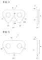
- FIG. 4( a ) is an enlarged front view of a link plate making up part of the silent chain, and ( b ) is an enlarged side view thereof;
- FIG. 5( a ) is an enlarged front view of a guide plate making up part of the silent chain, and ( b ) is an enlarged side view thereof;
- FIG. 6 is a view corresponding to a cross section along the line VI-VI in FIG. 1 , illustrating the state of contact between the silent chain and the chain guide.
- FIGS. 1 to 6 are figures for illustrating the silent chain according to an exemplary embodiment of the present invention, where FIG. 1 is a schematic of the structure of a camshaft timing system in an engine which employs the silent chain according to this exemplary embodiment; FIGS. 2 and 3 are partial oblique views of the silent chain; FIG. 4( a ) is a front view of a link plate, and (b) is a side view thereof; FIG. 5( a ) is a front view of a guide plate, and (b) is a side view thereof; and FIG. 6 is a view in cross section along the line VI-VI in FIG. 1 .
- a camshaft timing system 100 in an engine which employs the silent chain according to this exemplary embodiment is provided with a crank sprocket 51 mounted on a crankshaft 50 , cam sprockets 54 , 55 mounted on two camshafts 52 , 53 , respectively, and a silent chain 1 which is wound around these sprockets 51 , 54 , 55 .
- the clockwise arrows denote the direction of rotation of each of the sprockets 51 , 54 , 55 .
- a chain guide 56 for guiding the travel of the chain 1 is arranged at the tension side span of the silent chain 1 .
- the chain guide 56 is fixed to a member on the engine side by way of fixing bolts 56 a , 56 b which are provided at both ends thereof.
- the chain guide 56 has a chain sliding surface 56 A on which the travelling chain 1 slides, and a pair of guide walls 56 B which are arranged at the left and right edges of the chain sliding surface 56 A and stand upright therefrom.
- a tensioner arm 57 for maintaining the tension of the chain 1 is arranged at the slack side span of the silent chain 1 .
- the tensioner arm 57 is mounted so as to be able to swine on the engine side member by way of a pivot bolt 57 a which is provided at the pivoting end thereof.
- a tensioner 58 for exerting a pressing force on the tensioner arm 57 is provided at the free end of the tensioner arm 57 .
- the tip end of a piston rod 58 a of the tensioner 58 abuts the free end of the tensioner arm 57 .
- the tensioner arm 57 has a chain sliding surface 57 A on which the travelling chain 1 slides, and a pair of guide walls 57 B which are arranged at the left and right edges of the chain sliding surface 57 A and stand upright therefrom.
- this silent chain 1 has a configuration in which a large number of link plates 2 are stacked in the thickness direction (the direction of the arrow A in FIG. 2 ) and the length direction (the direction of the arrow B in this figure), and these link plates 2 are pivotably linked to one another by linking pins 3 , while guide plates 4 are arranged at the outermost side thereof and in the centre in the chain width direction (the direction of the arrow A in this figure) and mounted on the linking pins 3 .
- the outermost guide plates 4 are fixedly attached to both ends of the linking pins 3 by means of riveting or the like.
- the silent chain 1 has a plurality of guide rows G which are arranged at the same positions in the chain length direction as the guide plates 4 (the direction of the arrow B in FIG. 2 ) and consist of link plates 2 and guide plates 4 , and a plurality of non-guide rows L which are arranged between each of the adjoining guide rows G in the chain length direction and consist of link plates 2 only, without any guide plates 4 .
- the guide rows G and non-guide rows L are alternately arranged in the chain length direction.
- the link plates 2 have a pair of pin holes 21 and tooth parts 22 .
- a linking pin 3 is inserted into each pin hole 21 .
- Each tooth part 22 consists of inner flank surfaces 22 a and outer flank surfaces 22 b which mesh with the sprocket teeth (not depicted), and each inner flank surface 22 a is linked by way of a crotch part 23 .
- the height of the back part 24 of the link plate 2 is h, and the thickness is t.
- the guide plates 4 are roughly rectangular plates having a pair of pin holes 41 ; they do not have tooth parts, and a guide part 43 for positioning the silent chain 1 with respect to the sprockets when the silent chain 1 is wound on the sprockets is formed at the bottom thereof.
- the height of the back part 44 of the guide plate 4 is H, this height H being greater than the height h of the back part 24 of the link plate 2 (i.e. H>h).
- the thickness of the guide plate 4 is T, this thickness T being smaller than the thickness t of the link plate 2 (i.e. T ⁇ t).
- FIG. 6 shows a cross section in the chain width direction passing through the centre of the guide plates 4 in conjunction with the chain guide 56 .
- the link plates 2 and guide plates 4 in the guide row G are shown with diagonal lines, and the link plates 2 of the non-guide row L adjoining these in the chain length direction are shown in outline.
- the guide plates 4 in the guide row G are provided in two places at the outermost sides and in one place at a central position, making a total of three places. Furthermore, only the back parts 44 of the guide plates 4 come into contact with the chain sliding surface 56 A of the chain guide 56 .
- the guide plates 4 of the guide row G are arranged not only in positions at both ends in the chain width direction, but also in a central position in the chain width direction.
- the thickness T of the guide plates 4 in this case is smaller than the thickness t of the link plates 2 , and therefore the rigidity of the guide plates 4 can be reduced (the guide plates 4 can be endowed with the same degree of rigidity as the link plates 2 especially when the thickness T is 60-70% of the thickness t), and the pitch balance during the prestressing operation can be further improved.
- the silent chain 1 slides over the chain guide 56 and tensioner arm 57 as it travels.
- the height of the back parts 44 of the guide plates 4 is greater than the height of the back parts 24 of the link plates 2 in the guide rows G and non-guide rows L, and therefore when the silent chain 1 is in contact with the chain guide 56 , only the back parts 44 of the guide plates 4 slide over the chain sliding surface 56 A of the chain guide 56 , and by means of this the sliding resistance of the chain as it travels can be reduced, and friction losses can be reduced.
- the back parts 24 of the link plates 2 need not undergo finishing, and at least the back parts 44 only of the guide plates 4 may undergo finishing (punching by means of fine blanking, for example).
- a space C (see FIG. 6 ) is formed between the back parts 24 of the link plates 2 of the silent chain 1 and the chain sliding surfaces 56 A, 57 A, and therefore the heat which is generated between the back face parts of the silent chain and the chain sliding surfaces 56 A, 57 A can be released outside the chain sliding surfaces 56 A, 57 A because of this space C, which makes it possible to suppress the generation of heat and makes it possible to prevent oxidation of the oil. Furthermore, fresh oil can be supplied into the space C, making it possible to prevent deterioration of the oil.
Landscapes
- Engineering & Computer Science (AREA)
- General Engineering & Computer Science (AREA)
- Mechanical Engineering (AREA)
- Devices For Conveying Motion By Means Of Endless Flexible Members (AREA)
Applications Claiming Priority (3)
| Application Number | Priority Date | Filing Date | Title |
|---|---|---|---|
| JP2008-161656 | 2008-06-20 | ||
| JP2008161656A JP5386116B2 (ja) | 2008-06-20 | 2008-06-20 | サイレントチェーン |
| PCT/US2009/047358 WO2009155238A2 (en) | 2008-06-20 | 2009-06-15 | Silent chain |
Publications (2)
| Publication Number | Publication Date |
|---|---|
| US20110224041A1 US20110224041A1 (en) | 2011-09-15 |
| US8979691B2 true US8979691B2 (en) | 2015-03-17 |
Family
ID=41434676
Family Applications (1)
| Application Number | Title | Priority Date | Filing Date |
|---|---|---|---|
| US12/997,308 Expired - Fee Related US8979691B2 (en) | 2008-06-20 | 2009-06-15 | Silent chain |
Country Status (6)
| Country | Link |
|---|---|
| US (1) | US8979691B2 (de) |
| EP (1) | EP2300733B1 (de) |
| JP (1) | JP5386116B2 (de) |
| KR (1) | KR101541703B1 (de) |
| CN (1) | CN102057181B (de) |
| WO (1) | WO2009155238A2 (de) |
Cited By (4)
| Publication number | Priority date | Publication date | Assignee | Title |
|---|---|---|---|---|
| US10359097B2 (en) * | 2016-06-07 | 2019-07-23 | Hall Labs Llc | Silent chain profile for linear movement |
| US10400857B2 (en) | 2016-12-29 | 2019-09-03 | Yushin Precision Industrial Co., Ltd. | Silent chain |
| US20220003295A1 (en) * | 2019-03-22 | 2022-01-06 | Daido Kogyo Co., Ltd. | Chain transmission device |
| US20250052301A1 (en) * | 2023-08-07 | 2025-02-13 | Honda Motor Co., Ltd. | Power transmission device |
Families Citing this family (7)
| Publication number | Priority date | Publication date | Assignee | Title |
|---|---|---|---|---|
| JP5520428B2 (ja) * | 2009-08-31 | 2014-06-11 | ボーグワーナー インコーポレーテッド | サイレントチェーン |
| JP5614223B2 (ja) * | 2010-10-14 | 2014-10-29 | 日産自動車株式会社 | 無段変速伝動機構 |
| JP5944200B2 (ja) | 2012-04-04 | 2016-07-05 | 株式会社椿本チエイン | サイレントチェーン |
| JP5421448B1 (ja) * | 2012-11-22 | 2014-02-19 | 大同工業株式会社 | サイレントチェーン及びサイレントチェーン伝動装置 |
| DE112015003844T5 (de) * | 2014-08-22 | 2017-07-27 | Schaeffler Technologies AG & Co. KG | Hochfeste umgekehrte Zahnradkette mit einer durch einen Presssitz montierten Mittelplatte |
| DE202015003932U1 (de) * | 2015-05-29 | 2015-06-19 | Iwis Motorsysteme Gmbh & Co. Kg | Gelenkkette mit Dehnungs-Außenlasche |
| DE102017116245A1 (de) * | 2017-07-19 | 2019-01-24 | Schaeffler Technologies AG & Co. KG | Kette eines Kettentriebs, die über Mittellaschen geführt ist |
Citations (34)
| Publication number | Priority date | Publication date | Assignee | Title |
|---|---|---|---|---|
| US1840081A (en) * | 1926-10-14 | 1932-01-05 | Chrysler Corp | Chain |
| US1956942A (en) * | 1929-08-17 | 1934-05-01 | Whitney Mfg Co | Chain drive and chain for use thereon |
| US2525561A (en) * | 1946-09-05 | 1950-10-10 | Link Belt Co | Drive chain |
| US2718153A (en) * | 1953-06-02 | 1955-09-20 | George A Dean | Drive mechanism |
| US2770977A (en) * | 1953-11-27 | 1956-11-20 | Continental Gummi Werke Ag | Belt transmissions |
| US3120409A (en) * | 1962-04-23 | 1964-02-04 | Charles T Beall | Belt drive for track type tractor |
| US3597985A (en) * | 1970-02-05 | 1971-08-10 | Borg Warner | Flexible power transmission drive |
| US3656361A (en) * | 1969-07-29 | 1972-04-18 | Honda Motor Co Ltd | Silent chain-transmission apparatus |
| US5006096A (en) * | 1989-03-25 | 1991-04-09 | Breco Kunststoffverarbeitungs-Gmbh & Co. Kg | Belt drive comprising a toothed belt and a toothed pulley |
| US5013286A (en) * | 1989-03-25 | 1991-05-07 | Breco Kunststoffverarbeitungs-Gmbh & Co. Kg | Belt drive comprising a toothed belt and a toothed pulley |
| US5170883A (en) * | 1990-05-29 | 1992-12-15 | The Laitram Corporation | Laminated metal sprocket for plastic modular conveyor belts and methods of operating belt systems |
| US5456638A (en) * | 1994-07-21 | 1995-10-10 | Osborn; Merritt A. | Composite gear with restraining member |
| US5470282A (en) * | 1992-05-19 | 1995-11-28 | Borg-Warner Automotive, Inc. | Phased chain assemblies having links with a single toe |
| JPH10122308A (ja) | 1996-09-30 | 1998-05-15 | Borg Warner Automot Inc | サイレントチェーン |
| JPH11182634A (ja) | 1997-12-16 | 1999-07-06 | Tsubakimoto Chain Co | サイレントチェーン |
| US6106425A (en) * | 1998-09-18 | 2000-08-22 | Borg-Warner Automotive, Inc. | Single assembly phased chain |
| US20020006237A1 (en) * | 2000-06-14 | 2002-01-17 | Takashi Nakamura | Bearing structure |
| US20020025870A1 (en) * | 2000-08-29 | 2002-02-28 | Nobuto Kozakura | Double-sided meshing type silent chain |
| US6364800B1 (en) * | 1998-09-21 | 2002-04-02 | Borgwarner Inc. | Interior guided chain system for lateral chain control |
| US6379278B1 (en) * | 1999-07-14 | 2002-04-30 | Honda Giken Kogyo Kabushiki Kaisha | Vehicular transmission stop control system |
| US6419604B2 (en) * | 1998-12-24 | 2002-07-16 | Tsubakimoto Chain Co. | Double-meshing-type silent chain drive and sprocket used therein |
| US20020111238A1 (en) * | 2001-02-09 | 2002-08-15 | Isamu Okabe | Silent chain, sprocket for silent chain and silent chain transmission device |
| US6440022B1 (en) * | 1997-12-25 | 2002-08-27 | Tsubakimoto Chain Co. | Double-meshing type silent chain and sprocket for meshing with the chain along outer circumference thereof |
| US20020137583A1 (en) * | 2000-04-19 | 2002-09-26 | Thomas Fink | Chain drive, especially a camshaft/camshaft drive for a motor vehicle |
| US20020142874A1 (en) * | 2001-03-30 | 2002-10-03 | Markley George L. | Sprocket and chain for limiting chordal fall motion |
| US20030104891A1 (en) * | 2001-11-30 | 2003-06-05 | Toyonaga Saitoh | Silent chain |
| US20030216207A1 (en) * | 2002-04-16 | 2003-11-20 | Cheng Mu | Silent drive chain assembly having flexible links |
| US20040166978A1 (en) * | 2002-10-24 | 2004-08-26 | Borgwarner Morse Tec Japan K.K. | Silent chain and method of producing the same |
| US6855084B2 (en) * | 2002-08-20 | 2005-02-15 | Honda Giken Kogyo Kabushiki Kaisha | Power transmission system in vehicle |
| US20060068959A1 (en) * | 2004-09-24 | 2006-03-30 | Young James D | Inverted tooth chain system with inside flank engagement |
| US20060094551A1 (en) * | 2004-11-04 | 2006-05-04 | Tsubakimoto Chain Co. | Silent chain and method of producing same |
| US7094170B2 (en) * | 2002-05-06 | 2006-08-22 | Cloyes Gear And Products, Inc. | Cushioned sprocket and improved inverted tooth chain for use with same |
| US20080293530A1 (en) * | 2007-05-22 | 2008-11-27 | Jatco Ltd | Oil pump driving mechanism |
| US7837583B2 (en) * | 2007-08-08 | 2010-11-23 | Tsubakimoto Chain Co. | Silent chain |
Family Cites Families (11)
| Publication number | Priority date | Publication date | Assignee | Title |
|---|---|---|---|---|
| JPS6422308A (en) | 1987-07-20 | 1989-01-25 | Organo Kk | Hollow yarn module using crimped hollow yarn |
| JP3271892B2 (ja) * | 1996-03-18 | 2002-04-08 | 本田技研工業株式会社 | サイレントチェーン |
| JP2001349384A (ja) * | 2000-06-05 | 2001-12-21 | Borg Warner Automotive Kk | 背面駆動型サイレントチェーン |
| DE10139123A1 (de) | 2000-09-06 | 2002-03-14 | Luk Lamellen & Kupplungsbau | Laschenkette |
| JP2002130385A (ja) * | 2000-10-26 | 2002-05-09 | Tsubakimoto Chain Co | 耐摩耗伸びサイレントチェーン |
| JP3734760B2 (ja) * | 2002-03-12 | 2006-01-11 | ボルグワーナー・モールステック・ジャパン株式会社 | サイレントチェーン |
| US20050049098A1 (en) * | 2003-08-28 | 2005-03-03 | Borgwarner Inc. | High-performance silent chain |
| JP2006144852A (ja) * | 2004-11-17 | 2006-06-08 | Tsubakimoto Chain Co | サイレントチェーン |
| JP3980033B2 (ja) * | 2005-03-16 | 2007-09-19 | 株式会社椿本チエイン | サイレントチェーン |
| JP2007092798A (ja) * | 2005-09-27 | 2007-04-12 | Tsubakimoto Chain Co | サイレントチェーン |
| JP2007187181A (ja) * | 2006-01-11 | 2007-07-26 | Tsubakimoto Chain Co | サイレントチェーン |
-
2008
- 2008-06-20 JP JP2008161656A patent/JP5386116B2/ja not_active Expired - Fee Related
-
2009
- 2009-06-15 EP EP09767548A patent/EP2300733B1/de not_active Not-in-force
- 2009-06-15 CN CN200980121646.2A patent/CN102057181B/zh not_active Expired - Fee Related
- 2009-06-15 WO PCT/US2009/047358 patent/WO2009155238A2/en not_active Ceased
- 2009-06-15 KR KR1020117000886A patent/KR101541703B1/ko not_active Expired - Fee Related
- 2009-06-15 US US12/997,308 patent/US8979691B2/en not_active Expired - Fee Related
Patent Citations (37)
| Publication number | Priority date | Publication date | Assignee | Title |
|---|---|---|---|---|
| US1840081A (en) * | 1926-10-14 | 1932-01-05 | Chrysler Corp | Chain |
| US1956942A (en) * | 1929-08-17 | 1934-05-01 | Whitney Mfg Co | Chain drive and chain for use thereon |
| US2525561A (en) * | 1946-09-05 | 1950-10-10 | Link Belt Co | Drive chain |
| US2718153A (en) * | 1953-06-02 | 1955-09-20 | George A Dean | Drive mechanism |
| US2770977A (en) * | 1953-11-27 | 1956-11-20 | Continental Gummi Werke Ag | Belt transmissions |
| US3120409A (en) * | 1962-04-23 | 1964-02-04 | Charles T Beall | Belt drive for track type tractor |
| US3656361A (en) * | 1969-07-29 | 1972-04-18 | Honda Motor Co Ltd | Silent chain-transmission apparatus |
| US3597985A (en) * | 1970-02-05 | 1971-08-10 | Borg Warner | Flexible power transmission drive |
| US5013286A (en) * | 1989-03-25 | 1991-05-07 | Breco Kunststoffverarbeitungs-Gmbh & Co. Kg | Belt drive comprising a toothed belt and a toothed pulley |
| US5006096A (en) * | 1989-03-25 | 1991-04-09 | Breco Kunststoffverarbeitungs-Gmbh & Co. Kg | Belt drive comprising a toothed belt and a toothed pulley |
| US5170883A (en) * | 1990-05-29 | 1992-12-15 | The Laitram Corporation | Laminated metal sprocket for plastic modular conveyor belts and methods of operating belt systems |
| US5470282A (en) * | 1992-05-19 | 1995-11-28 | Borg-Warner Automotive, Inc. | Phased chain assemblies having links with a single toe |
| US5456638A (en) * | 1994-07-21 | 1995-10-10 | Osborn; Merritt A. | Composite gear with restraining member |
| JPH10122308A (ja) | 1996-09-30 | 1998-05-15 | Borg Warner Automot Inc | サイレントチェーン |
| US5758484A (en) * | 1996-09-30 | 1998-06-02 | Borg-Warner Automotive, Inc. | Silent chain with raised link backs |
| JPH11182634A (ja) | 1997-12-16 | 1999-07-06 | Tsubakimoto Chain Co | サイレントチェーン |
| US6440022B1 (en) * | 1997-12-25 | 2002-08-27 | Tsubakimoto Chain Co. | Double-meshing type silent chain and sprocket for meshing with the chain along outer circumference thereof |
| US6106425A (en) * | 1998-09-18 | 2000-08-22 | Borg-Warner Automotive, Inc. | Single assembly phased chain |
| US6364800B1 (en) * | 1998-09-21 | 2002-04-02 | Borgwarner Inc. | Interior guided chain system for lateral chain control |
| US6419604B2 (en) * | 1998-12-24 | 2002-07-16 | Tsubakimoto Chain Co. | Double-meshing-type silent chain drive and sprocket used therein |
| US6379278B1 (en) * | 1999-07-14 | 2002-04-30 | Honda Giken Kogyo Kabushiki Kaisha | Vehicular transmission stop control system |
| US20020137583A1 (en) * | 2000-04-19 | 2002-09-26 | Thomas Fink | Chain drive, especially a camshaft/camshaft drive for a motor vehicle |
| US6988831B2 (en) * | 2000-06-14 | 2006-01-24 | Honda Giken Kogyo Kabushiki Kaisha | Bearing structure |
| US20020006237A1 (en) * | 2000-06-14 | 2002-01-17 | Takashi Nakamura | Bearing structure |
| US20020025870A1 (en) * | 2000-08-29 | 2002-02-28 | Nobuto Kozakura | Double-sided meshing type silent chain |
| US20020111238A1 (en) * | 2001-02-09 | 2002-08-15 | Isamu Okabe | Silent chain, sprocket for silent chain and silent chain transmission device |
| US20020142874A1 (en) * | 2001-03-30 | 2002-10-03 | Markley George L. | Sprocket and chain for limiting chordal fall motion |
| US6575861B2 (en) * | 2001-03-30 | 2003-06-10 | Borgwarner, Inc. | Sprocket and chain for limiting chordal fall motion |
| US20030104891A1 (en) * | 2001-11-30 | 2003-06-05 | Toyonaga Saitoh | Silent chain |
| US20030216207A1 (en) * | 2002-04-16 | 2003-11-20 | Cheng Mu | Silent drive chain assembly having flexible links |
| US7094170B2 (en) * | 2002-05-06 | 2006-08-22 | Cloyes Gear And Products, Inc. | Cushioned sprocket and improved inverted tooth chain for use with same |
| US6855084B2 (en) * | 2002-08-20 | 2005-02-15 | Honda Giken Kogyo Kabushiki Kaisha | Power transmission system in vehicle |
| US20040166978A1 (en) * | 2002-10-24 | 2004-08-26 | Borgwarner Morse Tec Japan K.K. | Silent chain and method of producing the same |
| US20060068959A1 (en) * | 2004-09-24 | 2006-03-30 | Young James D | Inverted tooth chain system with inside flank engagement |
| US20060094551A1 (en) * | 2004-11-04 | 2006-05-04 | Tsubakimoto Chain Co. | Silent chain and method of producing same |
| US20080293530A1 (en) * | 2007-05-22 | 2008-11-27 | Jatco Ltd | Oil pump driving mechanism |
| US7837583B2 (en) * | 2007-08-08 | 2010-11-23 | Tsubakimoto Chain Co. | Silent chain |
Cited By (6)
| Publication number | Priority date | Publication date | Assignee | Title |
|---|---|---|---|---|
| US10359097B2 (en) * | 2016-06-07 | 2019-07-23 | Hall Labs Llc | Silent chain profile for linear movement |
| US10400857B2 (en) | 2016-12-29 | 2019-09-03 | Yushin Precision Industrial Co., Ltd. | Silent chain |
| US20220003295A1 (en) * | 2019-03-22 | 2022-01-06 | Daido Kogyo Co., Ltd. | Chain transmission device |
| US11927244B2 (en) * | 2019-03-22 | 2024-03-12 | Daido Kogyo Co., Ltd. | Chain transmission device |
| US20250052301A1 (en) * | 2023-08-07 | 2025-02-13 | Honda Motor Co., Ltd. | Power transmission device |
| US12553497B2 (en) * | 2023-08-07 | 2026-02-17 | Honda Motor Co., Ltd. | Power transmission device |
Also Published As
| Publication number | Publication date |
|---|---|
| WO2009155238A3 (en) | 2010-03-11 |
| KR20110020911A (ko) | 2011-03-03 |
| JP5386116B2 (ja) | 2014-01-15 |
| EP2300733B1 (de) | 2012-09-05 |
| EP2300733A4 (de) | 2011-11-16 |
| WO2009155238A2 (en) | 2009-12-23 |
| KR101541703B1 (ko) | 2015-08-04 |
| JP2010001975A (ja) | 2010-01-07 |
| US20110224041A1 (en) | 2011-09-15 |
| EP2300733A2 (de) | 2011-03-30 |
| CN102057181B (zh) | 2015-07-15 |
| CN102057181A (zh) | 2011-05-11 |
Similar Documents
| Publication | Publication Date | Title |
|---|---|---|
| US8979691B2 (en) | Silent chain | |
| US8137226B2 (en) | Silent chain | |
| US20020061800A1 (en) | Wear-elongation resistant silent chain | |
| KR102124221B1 (ko) | 사일런트 체인 및 사일런트 체인 전동 장치 | |
| US20080096709A1 (en) | Chain transmission device | |
| US6805646B2 (en) | Double-sided meshing type silent chain | |
| WO2010138349A2 (en) | Guide plate and chain | |
| US8998758B2 (en) | Chain | |
| US9109658B2 (en) | Silent chain | |
| US20020132690A1 (en) | Silent chain | |
| JP2006144852A (ja) | サイレントチェーン | |
| JP4420946B2 (ja) | 両面噛合い型サイレントチェーン | |
| US8246498B2 (en) | Chain transmission device | |
| US20090131209A1 (en) | Rocker joint pin type silent chain | |
| US20090186729A1 (en) | Silent chain | |
| JP4762294B2 (ja) | ブシュ付きサイレントチェーン | |
| US20070161445A1 (en) | Silent chain | |
| US20120071287A1 (en) | Silent chain having deformable guide plates | |
| US20050130779A1 (en) | Chain with a mark | |
| JPH09250600A (ja) | サイレントチェーン | |
| US20070072717A1 (en) | Double-sided engagement type silent chain | |
| JP2020128811A (ja) | 伝動用チェーン | |
| KR20160030585A (ko) | 개선된 nvh 거동을 갖는 좁은 레이싱을 가능하게 해주는 교번적인 내측 링크 위치를 갖는 체인 |
Legal Events
| Date | Code | Title | Description |
|---|---|---|---|
| AS | Assignment |
Owner name: BORGWARNER MORSE TEC JAPAN K.K., JAPAN Free format text: ASSIGNMENT OF ASSIGNORS INTEREST;ASSIGNORS:TOKITA, TOSHIKAZU;YOSHIDA, YUKIO;MATSUDA, AKIO;REEL/FRAME:030667/0093 Effective date: 20130611 |
|
| FEPP | Fee payment procedure |
Free format text: PAYOR NUMBER ASSIGNED (ORIGINAL EVENT CODE: ASPN); ENTITY STATUS OF PATENT OWNER: LARGE ENTITY |
|
| STCF | Information on status: patent grant |
Free format text: PATENTED CASE |
|
| MAFP | Maintenance fee payment |
Free format text: PAYMENT OF MAINTENANCE FEE, 4TH YEAR, LARGE ENTITY (ORIGINAL EVENT CODE: M1551); ENTITY STATUS OF PATENT OWNER: LARGE ENTITY Year of fee payment: 4 |
|
| FEPP | Fee payment procedure |
Free format text: MAINTENANCE FEE REMINDER MAILED (ORIGINAL EVENT CODE: REM.); ENTITY STATUS OF PATENT OWNER: LARGE ENTITY |
|
| LAPS | Lapse for failure to pay maintenance fees |
Free format text: PATENT EXPIRED FOR FAILURE TO PAY MAINTENANCE FEES (ORIGINAL EVENT CODE: EXP.); ENTITY STATUS OF PATENT OWNER: LARGE ENTITY |
|
| STCH | Information on status: patent discontinuation |
Free format text: PATENT EXPIRED DUE TO NONPAYMENT OF MAINTENANCE FEES UNDER 37 CFR 1.362 |
|
| FP | Lapsed due to failure to pay maintenance fee |
Effective date: 20230317 |