US8992596B2 - Device and method for producing an endoprosthesis - Google Patents
Device and method for producing an endoprosthesis Download PDFInfo
- Publication number
- US8992596B2 US8992596B2 US12/576,102 US57610209A US8992596B2 US 8992596 B2 US8992596 B2 US 8992596B2 US 57610209 A US57610209 A US 57610209A US 8992596 B2 US8992596 B2 US 8992596B2
- Authority
- US
- United States
- Prior art keywords
- base body
- function element
- layer
- optionally
- approximately
- Prior art date
- Legal status (The legal status is an assumption and is not a legal conclusion. Google has not performed a legal analysis and makes no representation as to the accuracy of the status listed.)
- Expired - Fee Related, expires
Links
Images


Classifications
-
- A—HUMAN NECESSITIES
- A61—MEDICAL OR VETERINARY SCIENCE; HYGIENE
- A61L—METHODS OR APPARATUS FOR STERILISING MATERIALS OR OBJECTS IN GENERAL; DISINFECTION, STERILISATION OR DEODORISATION OF AIR; CHEMICAL ASPECTS OF BANDAGES, DRESSINGS, ABSORBENT PADS OR SURGICAL ARTICLES; MATERIALS FOR BANDAGES, DRESSINGS, ABSORBENT PADS OR SURGICAL ARTICLES
- A61L31/00—Materials for other surgical articles, e.g. stents, stent-grafts, shunts, surgical drapes, guide wires, materials for adhesion prevention, occluding devices, surgical gloves, tissue fixation devices
- A61L31/02—Inorganic materials
- A61L31/022—Metals or alloys
-
- A—HUMAN NECESSITIES
- A61—MEDICAL OR VETERINARY SCIENCE; HYGIENE
- A61L—METHODS OR APPARATUS FOR STERILISING MATERIALS OR OBJECTS IN GENERAL; DISINFECTION, STERILISATION OR DEODORISATION OF AIR; CHEMICAL ASPECTS OF BANDAGES, DRESSINGS, ABSORBENT PADS OR SURGICAL ARTICLES; MATERIALS FOR BANDAGES, DRESSINGS, ABSORBENT PADS OR SURGICAL ARTICLES
- A61L31/00—Materials for other surgical articles, e.g. stents, stent-grafts, shunts, surgical drapes, guide wires, materials for adhesion prevention, occluding devices, surgical gloves, tissue fixation devices
- A61L31/08—Materials for coatings
- A61L31/10—Macromolecular materials
-
- A—HUMAN NECESSITIES
- A61—MEDICAL OR VETERINARY SCIENCE; HYGIENE
- A61L—METHODS OR APPARATUS FOR STERILISING MATERIALS OR OBJECTS IN GENERAL; DISINFECTION, STERILISATION OR DEODORISATION OF AIR; CHEMICAL ASPECTS OF BANDAGES, DRESSINGS, ABSORBENT PADS OR SURGICAL ARTICLES; MATERIALS FOR BANDAGES, DRESSINGS, ABSORBENT PADS OR SURGICAL ARTICLES
- A61L31/00—Materials for other surgical articles, e.g. stents, stent-grafts, shunts, surgical drapes, guide wires, materials for adhesion prevention, occluding devices, surgical gloves, tissue fixation devices
- A61L31/14—Materials characterised by their function or physical properties, e.g. injectable or lubricating compositions, shape-memory materials, surface modified materials
- A61L31/148—Materials at least partially resorbable by the body
-
- A—HUMAN NECESSITIES
- A61—MEDICAL OR VETERINARY SCIENCE; HYGIENE
- A61L—METHODS OR APPARATUS FOR STERILISING MATERIALS OR OBJECTS IN GENERAL; DISINFECTION, STERILISATION OR DEODORISATION OF AIR; CHEMICAL ASPECTS OF BANDAGES, DRESSINGS, ABSORBENT PADS OR SURGICAL ARTICLES; MATERIALS FOR BANDAGES, DRESSINGS, ABSORBENT PADS OR SURGICAL ARTICLES
- A61L31/00—Materials for other surgical articles, e.g. stents, stent-grafts, shunts, surgical drapes, guide wires, materials for adhesion prevention, occluding devices, surgical gloves, tissue fixation devices
- A61L31/14—Materials characterised by their function or physical properties, e.g. injectable or lubricating compositions, shape-memory materials, surface modified materials
- A61L31/18—Materials at least partially X-ray or laser opaque
-
- A—HUMAN NECESSITIES
- A61—MEDICAL OR VETERINARY SCIENCE; HYGIENE
- A61L—METHODS OR APPARATUS FOR STERILISING MATERIALS OR OBJECTS IN GENERAL; DISINFECTION, STERILISATION OR DEODORISATION OF AIR; CHEMICAL ASPECTS OF BANDAGES, DRESSINGS, ABSORBENT PADS OR SURGICAL ARTICLES; MATERIALS FOR BANDAGES, DRESSINGS, ABSORBENT PADS OR SURGICAL ARTICLES
- A61L2420/00—Materials or methods for coatings medical devices
- A61L2420/02—Methods for coating medical devices
-
- C—CHEMISTRY; METALLURGY
- C25—ELECTROLYTIC OR ELECTROPHORETIC PROCESSES; APPARATUS THEREFOR
- C25D—PROCESSES FOR THE ELECTROLYTIC OR ELECTROPHORETIC PRODUCTION OF COATINGS; ELECTROFORMING; APPARATUS THEREFOR
- C25D11/00—Electrolytic coating by surface reaction, i.e. forming conversion layers
- C25D11/02—Anodisation
- C25D11/024—Anodisation under pulsed or modulated current or potential
-
- C—CHEMISTRY; METALLURGY
- C25—ELECTROLYTIC OR ELECTROPHORETIC PROCESSES; APPARATUS THEREFOR
- C25D—PROCESSES FOR THE ELECTROLYTIC OR ELECTROPHORETIC PRODUCTION OF COATINGS; ELECTROFORMING; APPARATUS THEREFOR
- C25D11/00—Electrolytic coating by surface reaction, i.e. forming conversion layers
- C25D11/02—Anodisation
- C25D11/026—Anodisation with spark discharge
-
- C—CHEMISTRY; METALLURGY
- C25—ELECTROLYTIC OR ELECTROPHORETIC PROCESSES; APPARATUS THEREFOR
- C25D—PROCESSES FOR THE ELECTROLYTIC OR ELECTROPHORETIC PRODUCTION OF COATINGS; ELECTROFORMING; APPARATUS THEREFOR
- C25D11/00—Electrolytic coating by surface reaction, i.e. forming conversion layers
- C25D11/02—Anodisation
- C25D11/04—Anodisation of aluminium or alloys based thereon
- C25D11/16—Pretreatment, e.g. desmutting
-
- C—CHEMISTRY; METALLURGY
- C25—ELECTROLYTIC OR ELECTROPHORETIC PROCESSES; APPARATUS THEREFOR
- C25D—PROCESSES FOR THE ELECTROLYTIC OR ELECTROPHORETIC PRODUCTION OF COATINGS; ELECTROFORMING; APPARATUS THEREFOR
- C25D11/00—Electrolytic coating by surface reaction, i.e. forming conversion layers
- C25D11/02—Anodisation
- C25D11/26—Anodisation of refractory metals or alloys based thereon
-
- Y—GENERAL TAGGING OF NEW TECHNOLOGICAL DEVELOPMENTS; GENERAL TAGGING OF CROSS-SECTIONAL TECHNOLOGIES SPANNING OVER SEVERAL SECTIONS OF THE IPC; TECHNICAL SUBJECTS COVERED BY FORMER USPC CROSS-REFERENCE ART COLLECTIONS [XRACs] AND DIGESTS
- Y10—TECHNICAL SUBJECTS COVERED BY FORMER USPC
- Y10T—TECHNICAL SUBJECTS COVERED BY FORMER US CLASSIFICATION
- Y10T29/00—Metal working
- Y10T29/49—Method of mechanical manufacture
- Y10T29/49826—Assembling or joining
- Y10T29/49908—Joining by deforming
- Y10T29/49938—Radially expanding part in cavity, aperture, or hollow body
- Y10T29/49943—Riveting
Definitions
- the present invention relates to a device, in particular for medical use as an endoprosthesis, preferably as an intraluminal endoprosthesis, having a base body comprising at least partially a metallic material, as well as a method for manufacturing such a device.
- Such stents or other endoprostheses as well as devices which can be used in aircraft engineering often have metallic materials in their base body.
- the metallic materials may form a biodegradable material which may also contain polymeric biodegradable materials.
- Biodegradation is understood to refer to hydrolytic, enzymatic and other metabolic degradation processes in a living body, caused mainly by body fluids coming in contact with the endoprosthesis and leading to gradual dissolution of at least large portions of the endoprosthesis.
- biocorrosion is often used as synonymous with the term biodegradation.
- bioresorption includes the subsequent resorption of degradation products by the living body.
- the present invention relates to endoprostheses or other devices having a base body whose material comprises a metallic material.
- a metallic material In addition to the aforementioned biodegradable materials, other metallic materials may also be considered.
- the position of a stent or other devices is often determined by means of imaging methods, e.g., by means of an X-ray device. Because of the low atomic number and low density of the biodegradable material, magnesium and its alloys, the radiopacity of the medical implants produced from magnesium is very low.
- medical devices may be furnished with function elements having a different material composition in comparison with the material of the base body in at least a portion of their volume.
- markers or function elements contain in particular a material that absorbs X-rays and/or other electromagnetic radiation to a greater extent (hereinafter referred to as radiopaque and/or radiologically opaque material) than does the material of the base body.
- U.S. Pat. No. 6,293,966 B1 discloses a stent with radiopaque marker elements having C-shaped elements on its distal and/or proximal ends, these C-shaped elements form an essentially spherical receptacle. Marker elements having spherical end sections are inserted into these receptacles. The spherical end sections are attached in a form-fitting manner and, if necessary, are secured by means of a weld in the receptacles formed by the C-shaped elements.
- the document DE 698 36 656 T2 shows and describes a bioabsorbable marker with radiopaque constituents for use on an implantable endoprosthesis such as a stent.
- the bioabsorbable radiopaque markers have porous sections, for example, which are filled with radiopaque material.
- a marker having hollow, void-like and porous sections filled with radiopaque material is also described.
- the prior art discloses a marker designed as an elongated element such as a filament, which is wrapped around parts of the implantable endoprosthesis.
- the actual contact area of the marker material with the magnesium is minimized and the local element binding is suppressed.
- the holding forces exerted by the magnesium and the X-ray markers are limited due to the low strength of the polymer and the differences in the modulus of elasticity of the two materials. After only a few days, this leads to a loss of strength of the composite after only a few days and also to an associated risk that the X-ray markers will be dissolved out of the implant.
- the object of the present invention is thus to create a device with which direct metal contact of the function element with the base body is reduced while at the same time achieving a high bonding strength.
- the object is also to provide an inexpensive method for producing such a device.
- a device comprising a first layer applied to and/or introduced into the base body at least in or on the borderline area that is between the base body and the function element and extends to the surface, such that said first laye is produced by a plasma-chemical treatment in an aqueous solution containing phosphate ions, or comprises magnesium stearate.
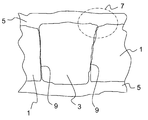
- FIG. 1 is a schematic diagram of a cross section through a first exemplary embodiment of an inventive device.
- FIG. 2 is a schematic diagram of an enlarged detail of FIG. 1 .
- FIG. 3 is a schematic diagram of a cross section through a second exemplary embodiment of an inventive device.
- the inventive device disclosed has the advantage that direct metal contact between the function element and base body is reduced, while at the same time a high strength of the composite is achieved.
- the degradation time of such a device is lengthened significantly and the persistence of the function element on the device, even with advanced degradation, is ensured in this way.
- the base body has at least one at least largely biodegradable metallic material, preferably magnesium or a magnesium alloy.
- the thickness of the first layer produced by the plasma-chemical treatment on the base body surface is approx. 1 ⁇ m to approx. 20 ⁇ m, preferably approx. 2 ⁇ m to approx. 8 ⁇ m.
- a second layer with at least one polymer from the group including parylene, polyurethane and magnesium stearate is arranged on the first layer, at least in the borderline area that is between the base body and the function element and is accessible to the surface.
- Parylenes are understood here to be completely linear, partially crystalline and uncrosslinked aromatic polymers. These polymers can be divided into four different basic types according to their structure, namely parylene C, parylene D, parylene N and parylene F. Parylene can preferably be applied to the function element by means of a vapor deposition process.
- the function element preferably has one or more radiopaque and/or radiologically opaque elements or compounds from the group including platinum, iridium, gold, tungsten, molybdenum, niobium, tantalum, yttrium, zirconium, ytterbium or alloys of these metals.
- the second layer has a layer thickness between approx. 0.5 ⁇ m and approx. 5 ⁇ m.
- the inventive procedure constitutes an inexpensive method for producing a device having the advantages given above.
- the first layer is rinsed in a solvent, preferably distilled H 2 O, after the plasma-chemical treatment, and then is dried, preferably at a temperature of at least 80° C. and especially preferably at least approx. 100° C., with the drying preferably being performed in a circulating air oven.
- a solvent preferably distilled H 2 O
- a buffer preferably potassium dihydrogen phosphate and/or sodium dihydrogen phosphate
- a buffer preferably potassium dihydrogen phosphate and/or sodium dihydrogen phosphate
- calcium dihydrogen phosphate may also be present as a buffer in the aqueous solution, its low water solubility being increased by the addition of complexing agents such as ethylenediamine, if necessary.
- the plasma-chemical treatment of the body surface is performed by applying a pulsed voltage to the base body with an amplitude exceeding, for a portion of the treatment period, a characteristic bath voltage for the material of the function element and then preferably rising in the course of the treatment.
- the function element is attached to the base body by pressing, riveting, laser welding and/or electron beam welding.
- the current density in the plasma-chemical treatment amounts to at least approx. 8 mA/cm 2 .
- the inventive device has a layer system, in particular on an absorbable magnesium implant, which is furnished with function elements comprising tungsten, tantalum, molybdenum, niobium and zirconium as well as their alloys, which function as X-ray markers.
- the X-ray marker is first joined to the base body by means of known technologies such as impressing, riveting, laser welding or electron beam welding.
- this component (device), which now comprises a composite material.
- the contacting material here comprises an aluminum or titanium wire.
- it is immersed in an aqueous solution containing phosphate. After applying a pulsed. steadily rising bath voltage characterized by long pulse pauses, the material of the base body and that of the function element are oxidized.
- oxide layers of different thicknesses are formed on the surface.
- an interfacial layer is formed between the oxides of the base material and the oxides of the function element, which is in the form of an X-ray marker, for example. Due to the formation of the oxide layer on the surface, direct contact between the material of the base body and the material of the function element which promotes corrosion is shifted to the interior area (inside) and thus beneath the surface of the device.
- the oxide layer on the function element continues to grow.
- a bath voltage of approx. 230 V for titanium, for example, or 260 V for tungsten, for example, which is characteristic of the material of this function element the originally pure plasma-chemically produced oxide layer is converted to a mixed phosphate/oxide layer of the function element surface takes place due to the plasma-chemical effect.
- the thickness of the oxide/mixed phosphate layer on the function element surface increases as a function of the bath voltage.
- the plasma-chemical process must proceed under different conditions than the coating of the individual components. It is advantageous in particular if the respective oxide layers grow slowly, because otherwise the oxide with the highest enthalpy of formation cannot develop a coherent layer. According to the present invention, slow growth of the oxide layer is achieved by long pauses between the voltage pulses, which may be up to 500 milliseconds long. This leads to a recombination of the irregularities (caused by the plasma-chemical effects) in the phosphate and oxide layers of the metals of the base body and function element.
- a uniform transition in the composition is achieved at the surface and down to a depth of approx. 10 ⁇ m, depending on the bath voltage applied, of the interface between the base body and the function element. Due to the plasma-chemical effects, which at higher bath voltages cause melting of the material of the base body and the material of the function element and partial conversion to the vapor phase, there is a thorough mixing of the materials of the base body and the function element as well as thorough mixing of the corresponding oxides and phosphates in the area of the first layer.
- the inventive surface layer may also serve as a base layer for a subsequent layer containing parylene. In such a layer combination, the degradation time of the device is increased again significantly.
- the area around the function element or the entire device may be coated with a polymer (parylene, polyurethane, magnesium stearate).
- Additional advantages include: solid markers are used with have a high radiopacity (cf. prior art with a material suspended in the polymer); an integrally bonded or form-fitting (pressed/riveted) connection between the base body and the material of the function element is achieved without adding a third material (such as polymers or adhesives); direct metal/metal contact of base body and function element at the surface of the device is prevented (this prevents the formation of a local element there and corrosion is inhibited); both metals are passivated in one process step.
- an active pharmaceutical substance (or active therapeutic substance or active ingredient) is understood to be an active ingredient (medication) of plant or animal origin or produced synthetically or a hormone, which is used in a suitable dosage as a therapeutic agent to influence states or functions of the body, as a substitute for natural active ingredients produced by the human or animal body, such as insulin, and for eliminating or neutralizing disease pathogens, tumors, cancer cells or exogenous substances): furthermore, there is the possibility of loading the surface of the function element with carriers of an active pharmaceutical
- the base body 1 of an inventive device in the form of a medical stent made of the magnesium alloy WE 43 shown in FIG. 1 is joined to a function element 3 in the form of an X-ray marker of tungsten, tantalum, zirconium or niobium or alloys thereof in a positive and/or integrally bonded manner by means of riveting, electron beam welding or laser welding.
- the resulting composite element of the base body and function element is then anodically contacted and immersed in an aqueous electrolyte having the following composition (based on 1 liter H 2 O): 80 g KH 2 PO 4, 45 g Na 2 CO 3, 65 mL ED (99%), 5 g to 10 g NaOH, and is plasma-chemically oxidized.
- a final bath voltage of 200 to 500 V when using pulsed currents with a duty cycle of 5 ms on and 100 ms off (in the extreme case up to 500 milliseconds off) and a current density of 100 mA/cm 2 a first layer 5 of oxides, mixed oxides, phosphates and mixed phosphates as well as spinels of the respective metallic base materials is formed at the surface.
- the final bath voltage to be set depends on the material of the X-ray marker. If a layer thickness of 3 ⁇ m on the magnesium surface with a layer thickness of 1.5 ⁇ m on the X-ray marker of tungsten is thus achieved at a final bath voltage of 260 V. After reaching this final voltage, the current density drops down to half the value originally set.
- the stent is removed from the bath and rinsed thoroughly under running distilled water and dried in hot air at approx. 40° C. Next the stent is carefully separated from the contacting material and stored dry and/or under an inert atmosphere until being processed further.
- FIG. 2 A detail 7 of the structure shown in FIG. 1 is shown on an enlarged scale in FIG. 2 .
- the joining Lone 9 in which the function element 3 is joined/attached in a positive and/or form-fitting and/or integrally bonded manner to the base body 1 can be seen in the enlargement.
- the joining zone 9 is covered with the first layer 5 , which has a different composition in each of the different zones and/or areas of the first layer 5 outlined by dotted lines in FIG. 2 .
- the first layer 5 contains essentially the oxides and/or phosphates of the function element 3 .
- both oxides and/or phosphates of the material of the function element 3 as well as oxides and/or phosphates of the material of base body 1 can be found above the transitional area between the function element 3 and the base body 1 .
- the area 12 of the first layer 5 situated above the base body 1 it comprises essentially oxides and/or phosphates of the material of the base body 1 .
- FIG. 3 shows another exemplary embodiment of an inventive device in which the function element 3 ′ is arranged in a layer and attached to the base body 1 ′.
- the first layer 5 ′ runs above the base body 1 ′ and the layered function element 3 ′.
- three different areas 10 ′, 11 ′ and 12 ′ with different material compositions, as in the first exemplary embodiment, can also be identified in the first layer 5 ′ in this exemplary embodiment.
- An inventive device in the form of a sheet of magnesium alloy AZ 31 approx. 1.8 mm thick is welded by electron beam welding, so it overlaps with a sheet of aluminum alloy AIMgSil 1.3 mm thick.
- the two materials in molten form are mixed in the joining zone. After solidification, there are three areas with different compositions.
- the middle joining area is characterized by gradients in the aluminum and magnesium distribution. Subsequently the joining area is finished mechanically by grinding and then cleaned and/or degreased at approx. 60° C. in a hot aqueous degreasing bath. After two short rinsings in distilled water, the welded component is contacted with an aluminum wire and is then plasma-chemically oxidized in the electrolyte described in Example 1.
- a layer of oxides and phosphates of the respective base material 8 ⁇ m thick is formed on the magnesium side and on the aluminum side a layer approx. 3 ⁇ m thick is formed.
- An average layer thickness of approx. 5 ⁇ m is established with these process parameters in the joining zone. If a subsequent application necessitates a greater layer thickness, a final bath voltage of 280 V is specified.
- the layer thicknesses are then each increased by 2-3 ⁇ m.
- the inventive device coated in this way has a higher corrosion resistance under the influence of a salt spray environment than in the uncoated state.
- the porous surface structure typical of plasma-chemical processes ensures good adhesion for subsequent surface treatments such as painting and adhesive bonding.
- An inventive device in the form of a longeron or stringer of a load-bearing wing construction for aircraft consists of a titanium alloy TiAl6V4 which is joined by laser welding to frames made of forged magnesium alloy AZ 31.
- this composite material is provided with surface properties. which lead to a greater corrosion resistance on the one hand, while on the other hand also simplifying a downstream adhesive bonding and/or painting by eliminating additional pretreatment steps.
Landscapes
- Health & Medical Sciences (AREA)
- Epidemiology (AREA)
- Animal Behavior & Ethology (AREA)
- Heart & Thoracic Surgery (AREA)
- Surgery (AREA)
- Vascular Medicine (AREA)
- Veterinary Medicine (AREA)
- Life Sciences & Earth Sciences (AREA)
- Public Health (AREA)
- General Health & Medical Sciences (AREA)
- Inorganic Chemistry (AREA)
- Chemical & Material Sciences (AREA)
- Physics & Mathematics (AREA)
- Optics & Photonics (AREA)
- Materials For Medical Uses (AREA)
Applications Claiming Priority (3)
| Application Number | Priority Date | Filing Date | Title |
|---|---|---|---|
| DE102008054845.6 | 2008-12-18 | ||
| DE102008054845 | 2008-12-18 | ||
| DE200810054845 DE102008054845A1 (de) | 2008-12-18 | 2008-12-18 | Vorrichtung und Verfahre zur Herstellung derselben |
Publications (2)
| Publication Number | Publication Date |
|---|---|
| US20100161030A1 US20100161030A1 (en) | 2010-06-24 |
| US8992596B2 true US8992596B2 (en) | 2015-03-31 |
Family
ID=42102672
Family Applications (1)
| Application Number | Title | Priority Date | Filing Date |
|---|---|---|---|
| US12/576,102 Expired - Fee Related US8992596B2 (en) | 2008-12-18 | 2009-10-08 | Device and method for producing an endoprosthesis |
Country Status (3)
| Country | Link |
|---|---|
| US (1) | US8992596B2 (de) |
| EP (1) | EP2198899B1 (de) |
| DE (1) | DE102008054845A1 (de) |
Cited By (3)
| Publication number | Priority date | Publication date | Assignee | Title |
|---|---|---|---|---|
| US20100161053A1 (en) * | 2008-12-18 | 2010-06-24 | Biotronik Vi Patent Ag | Implant and Method for Manufacturing |
| US20180280143A1 (en) * | 2017-03-30 | 2018-10-04 | Devendra Gorhe | Methods of modifying the porous surface of implants |
| US12616576B2 (en) | 2022-06-29 | 2026-05-05 | Biomet Manufacturing, Llc | Methods of modifying the porous surface of implants |
Families Citing this family (5)
| Publication number | Priority date | Publication date | Assignee | Title |
|---|---|---|---|---|
| CA2802753C (en) | 2010-06-21 | 2018-07-31 | Zorion Medical, Inc. | Bioabsorbable implants |
| EP2399619B1 (de) | 2010-06-25 | 2015-08-05 | Biotronik AG | Implantat und Verfahren zur Herstellung desselben |
| US8986369B2 (en) | 2010-12-01 | 2015-03-24 | Zorion Medical, Inc. | Magnesium-based absorbable implants |
| EP3509648B1 (de) | 2016-09-09 | 2024-08-21 | Zimmer, Inc. | Monolithische zusammengesetzte orthopädische implantate und zugehörige verfahren |
| CN106938368B (zh) * | 2017-05-03 | 2023-09-19 | 桂林实创真空数控设备有限公司 | 一种带x射线防护的直线局部动密封运动机构 |
Citations (24)
| Publication number | Priority date | Publication date | Assignee | Title |
|---|---|---|---|---|
| US4246316A (en) * | 1975-11-05 | 1981-01-20 | Fuji Photo Film Co., Ltd. | Magnetic recording medium |
| US4768787A (en) * | 1987-06-15 | 1988-09-06 | Shira Chester S | Golf club including high friction striking face |
| US5225069A (en) * | 1991-05-21 | 1993-07-06 | Jenoptik Gmbh | Process for the production of oxide ceramic surface films on silicon-containing light metal cast alloys |
| US5571187A (en) * | 1992-02-27 | 1996-11-05 | Zimmer, Inc. | Implant having a metallic porous surface |
| EP0824900A2 (de) | 1996-08-22 | 1998-02-25 | Advanced Cardiovascular Systems, Inc. | Schutzbeschichtung eines mit einer radiopaken Zwischenschicht versehenen Stents |
| US6120545A (en) * | 1996-10-04 | 2000-09-19 | Accis Bv | Joint prosthesis having ceramic abrasion layer |
| US6293966B1 (en) * | 1997-05-06 | 2001-09-25 | Cook Incorporated | Surgical stent featuring radiopaque markers |
| US6355058B1 (en) * | 1999-12-30 | 2002-03-12 | Advanced Cardiovascular Systems, Inc. | Stent with radiopaque coating consisting of particles in a binder |
| DE10127770A1 (de) | 2001-06-07 | 2002-12-12 | Volkswagen Ag | Verfahren zur Erzeugung von Korrosionsschutzschichten auf Oberflächen aus Magnesium oder Magnesiumlegierungen |
| DE10325678A1 (de) | 2003-06-02 | 2004-12-23 | Biotronik Meß- und Therapiegeräte GmbH & Co. Ingenieurbüro Berlin | Verbindungssystem zur Verbindung eines Stents mit einem radioopaken Marker sowie Verfahren zur Herstellung einer Verbindung zwischen einem Stent und zwei oder mehreren radioopaken Markern |
| US20060016690A1 (en) | 2004-07-23 | 2006-01-26 | Ilya Ostrovsky | Method for producing a hard coating with high corrosion resistance on articles made anodizable metals or alloys |
| US20060224237A1 (en) | 2005-03-03 | 2006-10-05 | Icon Medical Corp. | Fragile structure protective coating |
| US20060222679A1 (en) * | 2005-03-31 | 2006-10-05 | Conor Medsystems, Inc. | System and method for loading a beneficial agent into a medical device |
| US20070207186A1 (en) * | 2006-03-04 | 2007-09-06 | Scanlon John J | Tear and abrasion resistant expanded material and reinforcement |
| US20080033531A1 (en) * | 2006-08-07 | 2008-02-07 | Biotronik Vi Patent Ag | Endoprosthesis and method for producing same |
| US20080033533A1 (en) | 2006-08-07 | 2008-02-07 | Biotronik Vi Patent Ag | Marker composite for medical implants |
| US20080051870A1 (en) | 2006-07-19 | 2008-02-28 | Ralf Kaufmann | Marker element for the precise implantation of stents |
| US20080057101A1 (en) | 2006-08-21 | 2008-03-06 | Wouter Roorda | Medical devices for controlled drug release |
| US20080086195A1 (en) | 2006-10-05 | 2008-04-10 | Boston Scientific Scimed, Inc. | Polymer-Free Coatings For Medical Devices Formed By Plasma Electrolytic Deposition |
| US20080160259A1 (en) * | 2006-12-28 | 2008-07-03 | Boston Scientific Scimed, Inc. | Medical devices and methods of making the same |
| EP1941918A2 (de) | 2006-12-19 | 2008-07-09 | BIOTRONIK VI Patent AG | Verfahren zur Herstellung einer korrosionshemmenden Beschichtung auf einem Implantat aus einer biokorrodierbaren Magnesiumlegierung sowie nach dem Verfahren hergestelltes Implantat |
| US20080177378A1 (en) * | 2007-01-19 | 2008-07-24 | Civention Ag | Partially bioabsorbable implant |
| US20080249638A1 (en) * | 2007-04-05 | 2008-10-09 | Cinvention Ag | Biodegradable therapeutic implant for bone or cartilage repair |
| US8029554B2 (en) * | 2007-11-02 | 2011-10-04 | Boston Scientific Scimed, Inc. | Stent with embedded material |
Family Cites Families (1)
| Publication number | Priority date | Publication date | Assignee | Title |
|---|---|---|---|---|
| US6174330B1 (en) | 1997-08-01 | 2001-01-16 | Schneider (Usa) Inc | Bioabsorbable marker having radiopaque constituents |
-
2008
- 2008-12-18 DE DE200810054845 patent/DE102008054845A1/de not_active Withdrawn
-
2009
- 2009-10-08 US US12/576,102 patent/US8992596B2/en not_active Expired - Fee Related
- 2009-11-30 EP EP09177440.6A patent/EP2198899B1/de not_active Not-in-force
Patent Citations (30)
| Publication number | Priority date | Publication date | Assignee | Title |
|---|---|---|---|---|
| US4246316A (en) * | 1975-11-05 | 1981-01-20 | Fuji Photo Film Co., Ltd. | Magnetic recording medium |
| US4768787A (en) * | 1987-06-15 | 1988-09-06 | Shira Chester S | Golf club including high friction striking face |
| US5225069A (en) * | 1991-05-21 | 1993-07-06 | Jenoptik Gmbh | Process for the production of oxide ceramic surface films on silicon-containing light metal cast alloys |
| US5571187A (en) * | 1992-02-27 | 1996-11-05 | Zimmer, Inc. | Implant having a metallic porous surface |
| EP0824900A2 (de) | 1996-08-22 | 1998-02-25 | Advanced Cardiovascular Systems, Inc. | Schutzbeschichtung eines mit einer radiopaken Zwischenschicht versehenen Stents |
| US6120545A (en) * | 1996-10-04 | 2000-09-19 | Accis Bv | Joint prosthesis having ceramic abrasion layer |
| US6293966B1 (en) * | 1997-05-06 | 2001-09-25 | Cook Incorporated | Surgical stent featuring radiopaque markers |
| US6355058B1 (en) * | 1999-12-30 | 2002-03-12 | Advanced Cardiovascular Systems, Inc. | Stent with radiopaque coating consisting of particles in a binder |
| DE10127770A1 (de) | 2001-06-07 | 2002-12-12 | Volkswagen Ag | Verfahren zur Erzeugung von Korrosionsschutzschichten auf Oberflächen aus Magnesium oder Magnesiumlegierungen |
| DE10325678A1 (de) | 2003-06-02 | 2004-12-23 | Biotronik Meß- und Therapiegeräte GmbH & Co. Ingenieurbüro Berlin | Verbindungssystem zur Verbindung eines Stents mit einem radioopaken Marker sowie Verfahren zur Herstellung einer Verbindung zwischen einem Stent und zwei oder mehreren radioopaken Markern |
| US20060241741A1 (en) | 2003-06-02 | 2006-10-26 | Daniel Lootz | connecting system for connecting a stent to a radiopaque marker and a process for the production of a connection between a stent and two or more radiopaque markers |
| US20060016690A1 (en) | 2004-07-23 | 2006-01-26 | Ilya Ostrovsky | Method for producing a hard coating with high corrosion resistance on articles made anodizable metals or alloys |
| US20060224237A1 (en) | 2005-03-03 | 2006-10-05 | Icon Medical Corp. | Fragile structure protective coating |
| US20060222679A1 (en) * | 2005-03-31 | 2006-10-05 | Conor Medsystems, Inc. | System and method for loading a beneficial agent into a medical device |
| US20070207186A1 (en) * | 2006-03-04 | 2007-09-06 | Scanlon John J | Tear and abrasion resistant expanded material and reinforcement |
| DE102006033399B4 (de) | 2006-07-19 | 2009-04-09 | Jotec Gmbh | Markersystem und Einführsystem für ein solches Markersystem |
| US20080051870A1 (en) | 2006-07-19 | 2008-02-28 | Ralf Kaufmann | Marker element for the precise implantation of stents |
| US20080033533A1 (en) | 2006-08-07 | 2008-02-07 | Biotronik Vi Patent Ag | Marker composite for medical implants |
| EP1886701A2 (de) | 2006-08-07 | 2008-02-13 | BIOTRONIK VI Patent AG | Markerkomposit für medizinische Implantate |
| EP1886650A1 (de) | 2006-08-07 | 2008-02-13 | BIOTRONIK VI Patent AG | Endoprothese und Verfahren zur Herstellung einer solchen |
| DE102006038233A1 (de) | 2006-08-07 | 2008-02-14 | Biotronik Vi Patent Ag | Markerkomposit für medizinische Implantate |
| US20080033531A1 (en) * | 2006-08-07 | 2008-02-07 | Biotronik Vi Patent Ag | Endoprosthesis and method for producing same |
| US20080057101A1 (en) | 2006-08-21 | 2008-03-06 | Wouter Roorda | Medical devices for controlled drug release |
| US20080086195A1 (en) | 2006-10-05 | 2008-04-10 | Boston Scientific Scimed, Inc. | Polymer-Free Coatings For Medical Devices Formed By Plasma Electrolytic Deposition |
| EP1941918A2 (de) | 2006-12-19 | 2008-07-09 | BIOTRONIK VI Patent AG | Verfahren zur Herstellung einer korrosionshemmenden Beschichtung auf einem Implantat aus einer biokorrodierbaren Magnesiumlegierung sowie nach dem Verfahren hergestelltes Implantat |
| US20080243242A1 (en) * | 2006-12-19 | 2008-10-02 | Biotronik Vi Patent Ag | Method for producing a corrosion-inhibiting coating on an implant made of a bio-corrodible magnesium alloy and implant produced according to the method |
| US20080160259A1 (en) * | 2006-12-28 | 2008-07-03 | Boston Scientific Scimed, Inc. | Medical devices and methods of making the same |
| US20080177378A1 (en) * | 2007-01-19 | 2008-07-24 | Civention Ag | Partially bioabsorbable implant |
| US20080249638A1 (en) * | 2007-04-05 | 2008-10-09 | Cinvention Ag | Biodegradable therapeutic implant for bone or cartilage repair |
| US8029554B2 (en) * | 2007-11-02 | 2011-10-04 | Boston Scientific Scimed, Inc. | Stent with embedded material |
Non-Patent Citations (3)
| Title |
|---|
| English Abstract Translation of DE10127770A1, (Dec. 2002). |
| English Abstract Translation of EP1886701, (Jun. 2010). |
| German search report for priority application DE 10 2008 054 845.6, (Jul. 2009). |
Cited By (6)
| Publication number | Priority date | Publication date | Assignee | Title |
|---|---|---|---|---|
| US20100161053A1 (en) * | 2008-12-18 | 2010-06-24 | Biotronik Vi Patent Ag | Implant and Method for Manufacturing |
| US9259516B2 (en) * | 2008-12-18 | 2016-02-16 | Biotronik Vi Patent Ag | Implant and method for manufacturing |
| US20180280143A1 (en) * | 2017-03-30 | 2018-10-04 | Devendra Gorhe | Methods of modifying the porous surface of implants |
| US10893944B2 (en) * | 2017-03-30 | 2021-01-19 | Biomet Manufacturing, Llc | Methods of modifying the porous surface of implants |
| US11395740B2 (en) | 2017-03-30 | 2022-07-26 | Biomet Manufacturing, Llc | Methods of modifying the porous surface of implants |
| US12616576B2 (en) | 2022-06-29 | 2026-05-05 | Biomet Manufacturing, Llc | Methods of modifying the porous surface of implants |
Also Published As
| Publication number | Publication date |
|---|---|
| DE102008054845A1 (de) | 2010-07-01 |
| EP2198899B1 (de) | 2015-10-07 |
| EP2198899A2 (de) | 2010-06-23 |
| US20100161030A1 (en) | 2010-06-24 |
| EP2198899A3 (de) | 2013-10-23 |
Similar Documents
| Publication | Publication Date | Title |
|---|---|---|
| US8992596B2 (en) | Device and method for producing an endoprosthesis | |
| US8603569B2 (en) | Implant and method for producing a degradation-inhibiting layer on the surface of an implant body | |
| US8337936B2 (en) | Implant and method for manufacturing same | |
| US8110088B2 (en) | Implant and method for manufacturing same | |
| US9259516B2 (en) | Implant and method for manufacturing | |
| EP1941918A2 (de) | Verfahren zur Herstellung einer korrosionshemmenden Beschichtung auf einem Implantat aus einer biokorrodierbaren Magnesiumlegierung sowie nach dem Verfahren hergestelltes Implantat | |
| US8741073B2 (en) | Implant and method for producing the same | |
| US10272183B2 (en) | Implant and method for manufacturing same | |
| US8846130B2 (en) | Implant and method for producing the same | |
| US20080033535A1 (en) | Stent having a structure made of a biocorrodible metallic material | |
| US20100145432A1 (en) | Implant and method for producing the same | |
| US20130338758A1 (en) | Biocorrodible magnesium alloy implant | |
| JP6815606B2 (ja) | マーカーを備えた生体吸収性ステント及びその製造方法 | |
| US20110307051A1 (en) | Bioerodible Endoprostheses Including Electrochemical Cell | |
| US11039902B2 (en) | Marker element and method for the production thereof | |
| US20100178311A1 (en) | Implant and method for its manufacture | |
| US20120041541A1 (en) | Implant and method for the production thereof | |
| US20190374303A1 (en) | Function marker element and method for production thereof | |
| Goyal et al. | Clinical Translation, Regulatory Considerations, and Future Perspectives: Challenges in Iron-Based Biodegradable Materials for Biomedical Applications |
Legal Events
| Date | Code | Title | Description |
|---|---|---|---|
| AS | Assignment |
Owner name: BIOTRONIK VI PATENT AG,SWITZERLAND Free format text: ASSIGNMENT OF ASSIGNORS INTEREST;ASSIGNORS:BAYER, ULLRICH;LOOTZ, DANIEL;REEL/FRAME:023349/0731 Effective date: 20090924 Owner name: BIOTRONIK VI PATENT AG, SWITZERLAND Free format text: ASSIGNMENT OF ASSIGNORS INTEREST;ASSIGNORS:BAYER, ULLRICH;LOOTZ, DANIEL;REEL/FRAME:023349/0731 Effective date: 20090924 |
|
| STCF | Information on status: patent grant |
Free format text: PATENTED CASE |
|
| AS | Assignment |
Owner name: BIOTRONIK AG, SWITZERLAND Free format text: ASSIGNMENT OF ASSIGNORS INTEREST;ASSIGNOR:BIOTRONIK VI PATENT AG;REEL/FRAME:045853/0610 Effective date: 20170926 |
|
| MAFP | Maintenance fee payment |
Free format text: PAYMENT OF MAINTENANCE FEE, 4TH YEAR, LARGE ENTITY (ORIGINAL EVENT CODE: M1551); ENTITY STATUS OF PATENT OWNER: LARGE ENTITY Year of fee payment: 4 |
|
| FEPP | Fee payment procedure |
Free format text: MAINTENANCE FEE REMINDER MAILED (ORIGINAL EVENT CODE: REM.); ENTITY STATUS OF PATENT OWNER: LARGE ENTITY |
|
| LAPS | Lapse for failure to pay maintenance fees |
Free format text: PATENT EXPIRED FOR FAILURE TO PAY MAINTENANCE FEES (ORIGINAL EVENT CODE: EXP.); ENTITY STATUS OF PATENT OWNER: LARGE ENTITY |
|
| STCH | Information on status: patent discontinuation |
Free format text: PATENT EXPIRED DUE TO NONPAYMENT OF MAINTENANCE FEES UNDER 37 CFR 1.362 |
|
| FP | Lapsed due to failure to pay maintenance fee |
Effective date: 20230331 |