US8995520B2 - Analog continuous-time phase equalizer for data transmission - Google Patents
Analog continuous-time phase equalizer for data transmission Download PDFInfo
- Publication number
- US8995520B2 US8995520B2 US13/027,262 US201113027262A US8995520B2 US 8995520 B2 US8995520 B2 US 8995520B2 US 201113027262 A US201113027262 A US 201113027262A US 8995520 B2 US8995520 B2 US 8995520B2
- Authority
- US
- United States
- Prior art keywords
- signal
- phase
- input signal
- coefficient
- data
- Prior art date
- Legal status (The legal status is an assumption and is not a legal conclusion. Google has not performed a legal analysis and makes no representation as to the accuracy of the status listed.)
- Active, expires
Links
Images


Classifications
-
- H—ELECTRICITY
- H04—ELECTRIC COMMUNICATION TECHNIQUE
- H04L—TRANSMISSION OF DIGITAL INFORMATION, e.g. TELEGRAPHIC COMMUNICATION
- H04L25/00—Baseband systems
- H04L25/02—Details ; arrangements for supplying electrical power along data transmission lines
- H04L25/03—Shaping networks in transmitter or receiver, e.g. adaptive shaping networks
- H04L25/03006—Arrangements for removing intersymbol interference
- H04L25/03012—Arrangements for removing intersymbol interference operating in the time domain
- H04L25/03019—Arrangements for removing intersymbol interference operating in the time domain adaptive, i.e. capable of adjustment during data reception
- H04L25/03057—Arrangements for removing intersymbol interference operating in the time domain adaptive, i.e. capable of adjustment during data reception with a recursive structure
-
- H—ELECTRICITY
- H04—ELECTRIC COMMUNICATION TECHNIQUE
- H04L—TRANSMISSION OF DIGITAL INFORMATION, e.g. TELEGRAPHIC COMMUNICATION
- H04L25/00—Baseband systems
- H04L25/02—Details ; arrangements for supplying electrical power along data transmission lines
- H04L25/03—Shaping networks in transmitter or receiver, e.g. adaptive shaping networks
- H04L25/03006—Arrangements for removing intersymbol interference
- H04L25/03012—Arrangements for removing intersymbol interference operating in the time domain
- H04L25/03114—Arrangements for removing intersymbol interference operating in the time domain non-adaptive, i.e. not adjustable, manually adjustable, or adjustable only during the reception of special signals
- H04L25/03133—Arrangements for removing intersymbol interference operating in the time domain non-adaptive, i.e. not adjustable, manually adjustable, or adjustable only during the reception of special signals with a non-recursive structure
-
- H—ELECTRICITY
- H04—ELECTRIC COMMUNICATION TECHNIQUE
- H04L—TRANSMISSION OF DIGITAL INFORMATION, e.g. TELEGRAPHIC COMMUNICATION
- H04L25/00—Baseband systems
- H04L25/02—Details ; arrangements for supplying electrical power along data transmission lines
- H04L25/03—Shaping networks in transmitter or receiver, e.g. adaptive shaping networks
- H04L25/03006—Arrangements for removing intersymbol interference
- H04L25/03012—Arrangements for removing intersymbol interference operating in the time domain
Definitions
- This disclosure relates generally to high-speed communication.
- ISI inter-symbol interference
- FIG. 1 illustrates an example pulse response of a channel with example ISI.
- FIG. 2 illustrates an example equalizer
- FIG. 3 illustrates an example 3-tap finite-impulse-response (FIR) filter with one pre-cursor tap and one post-cursor tap.
- FIR finite-impulse-response
- FIG. 4 illustrates an example adaptive phase-equalizer system.
- FIG. 5 illustrates another example adaptive phase-equalizer system.
- FIG. 6 illustrates another example adaptive phase-equalizer system.
- FIG. 7 illustrates an example adaptive control for linear equalizer gain and pre-emphasis coefficients of an example 3-tap FIR filter.
- FIG. 8 illustrates example effects of example phase equalization.
- FIG. 9 illustrates example phase distortion
- FIG. 10 illustrates an example filter-pattern decoder (FPD) for detecting frequency-dependent phase between f s / 4 and f s / 6 .
- FPD filter-pattern decoder
- FIG. 11 illustrates an example phase-distortion detector.
- FIG. 12 illustrates an example FPD for detecting frequency-dependent phase between f s / 2 and f s / 4 .
- FIG. 13 illustrates an example FPD for detecting frequency-dependent phase between f s / 6 and f s / 8 .
- FIG. 14 illustrates an example multi-dimensional phase-distortion detector using multiple FPDs, one for detecting frequency-dependent phase between f s / 4 and f s / 6 and another for detecting frequency-dependent phase between f s / 6 and f s / 8 .
- FIG. 15 illustrates an example phase-distortion detector using multiple FPDs for inter-symbol interference based on errors sampled by a data clock.
- FIG. 16 illustrates an example FPD for phase distortion based on error information sampled by a data clock.
- FIG. 17 illustrates a clock-recovery method for a decision-feedback equalizer (DFE).
- DFE decision-feedback equalizer
- FIG. 18 illustrates a phase-error detector
- FIG. 19 illustrates an example phase-error detector for an example clock-recovery method for an example decision-feedback equalizer (DFE).
- DFE decision-feedback equalizer
- FIG. 20 illustrates an example 2-tap FIR filter with one pre-cursor tap.
- FIG. 21 illustrates an example 4-tap FIR filter with two pre-cursor taps.
- FIG. 22 illustrates an example first-order continuous-time linear equalizer (CTLE) for a phase equalizer.
- CTLE continuous-time linear equalizer
- FIG. 23 illustrates an example implementation of an example first-order CTLE for an example phase equalizer
- FIG. 24 illustrates another example implementation of an example first-order CTLE for an example phase equalizer.
- FIG. 25 illustrates an example first-order CTLE.
- FIG. 26 illustrates another example first-order CTLE.
- FIG. 27 illustrates an example second-order CTLE for an example phase equalizer.
- FIG. 28 illustrates an example implementation of an example second-order CTLE for an example phase equalizer.
- FIG. 29 illustrates another example implementation of an example second-order CTLE for an example phase equalizer.
- FIG. 1 illustrates an example pulse response of a channel with example ISI.
- the pulse response includes a peak pulse response (cursor), ISI before the cursor (pre-cursor ISI), and ISI after the cursor (post-cursor ISI). Both pre-cursor ISI and post-cursor ISI may interfere with the reception of adjacent bits and degrade bit error rate (BER). As channel length increases, the pulse response may spread more widely in time, causing higher ISI.
- Equalizers are often used to compensate for ISI to increase maximal channel length or increase communication speed.
- an equalizer is a filter which approximates a reverse function of the channel transfer function to cancel distortion by the channel.
- the equalizer may be a linear equalizer (LE), a decision-feedback equalizer (DFE), or a combination of LE and DFE.
- FIG. 2 illustrates an example equalizer.
- the LE input may have pre-cursor ISI and post-cursor ISI due to high-frequency attenuation in the channel.
- the LE amplifies the attenuated high-frequency components to cancel pre-cursor ISI and part of post-cursor ISI.
- Residual ISI at the DFE input is emulated by a feedback filter in the DFE using decision circuit outputs. The emulated ISI is subtracted from the DFE input signal so that the ISI may be completely cancelled at the decision circuit input.
- the LE could in particular embodiments cancel all post-cursor ISI, but an LE-only scheme has the drawback of tending to amplify high-frequency noise.
- the LE may leave some post-cursor ISI which is cancelled by the DFE. Since the decision circuit removes the noise, the emulated ISI is substantially noiseless.
- the advantage of a DFE is that it substantially cancels ISI without amplifying noise.
- the DFE has limited capability to cancel ISI, because each tap of the feedback filter may emulate ISI for only a time span of only one unit interval (UI).
- UI unit interval
- the DFE cannot substantially cancel the pre-cursor ISI, because the DFE emulates ISI using prior decisions.
- Another drawback of the DFE is error propagation; once there is an error in recovered data, the error is likely to happen again in successive data due to wrong feedback by the DFE.
- LE characteristics are represented by a transfer function in the discrete-time domain or continuous-time domain.
- An LE in the discrete-time domain is either a finite-impulse-response (FIR) filter or an infinite-impulse-response (IIR) filter.
- An LE in the continuous-time domain is a continuous-time linear equalizer (CTLE).
- An LE may be a combination of an FIR filter, an IIR filter, and a CTLE.
- the LE is on the Rx side in FIG. 2 , it may be placed on the Tx side so that the signal is pre-distorted before transmission. As an alternative, it may be split to both the Tx and Rx sides.
- the DFE should be on the Rx side, because the DFE uses data values that are received immediately before.
- FIG. 3 illustrates an example 3-tap FIR filter with one pre-cursor tap and one post-cursor tap.
- Z ⁇ 1 represents a unit delay.
- C 0 is the cursor-tap coefficient with the maximum magnitude among the tap coefficients.
- the cursor tap is also called the center tap or the main tap.
- C ⁇ 1 is the pre-cursor tap coefficient that primarily cancels the pre-cursor ISI.
- C 1 is the post-cursor tap coefficient that primarily cancels the post-cursor ISI.
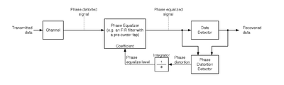
- FIG. 4 illustrates an example adaptive phase-equalizer system.
- the transmitted signal may be phase distorted during transmission over the channel.
- the phase-distorted signal may be phase-equalized by a phase equalizer such as an FIR filter with a pre-cursor tap to generate a phase-equalized signal.
- a data detector may recover transmitted data from the phase-equalized signal.
- the phase-distortion detector may check the data-detector input with the data-detector output to detect residual phase distortion in the data-detector input.
- the residual phase distortion may be integrated by an integrator to generate a phase-equalize level.
- the phase-equalize level may be used as a coefficient of the phase equalizer.
- the adaptive phase-equalizer system may include an amplitude equalizer.
- the phase equalizer may equalize amplitude distortion as well as phase distortion and the data detector may include a DFE.
- the phase equalizer of the adaptive phase-equalizer system may be placed on the Tx side, as FIG. 5 illustrates.
- the phase equalizer may pre-distort the signal before its transmission over the channel so it may be phase-equalized at the channel output.
- a backward channel may be required to transfer the coefficient control information back to Tx side.
- the functionality of the phase equalizer may be split between Tx and Rx.
- FIG. 6 illustrates another example adaptive phase-equalizer system.
- the phase-equalizer circuit may be realized by a 3-tap FIR filter with a pre-cursor tap on the Tx side.
- the Rx side may have a linear equalizer, a data and error detector with DFE, a de-multiplexer, clock-recovery circuits, and equalizer-control circuits.
- the equalizer control may generate LE controls, detector and DFE control, and pre-emphasis control.
- information for the pre-emphasis control may be transferred back to the Tx side through a backward control channel.
- Data is data recovered from the received signal and Error is error information for clock recovery and equalizer control.
- FIG. 7 illustrates an example adaptive control for LE gain and pre-emphasis coefficients of 3-tap FIR filter.
- filter-pattern decoders (FPDs) for ISI may detect residual ISI and generate ResISI signals at four time steps as described in U.S. Patent Application No. 2009/0316767, entitled Detecting Residual Intersymbol Interference (ISI) Components Using Two Data Patterns, which is incorporated herein by reference as an example and not by way of limitation.
- the ResISI signals at four time steps may be multiplied with weight constants, selected by a filter pattern balancer, and integrated to generate QRGain, which represents the gain of the linear equalizers at a quarter rate relative to DC.
- convergence may force the weighted sum of the average of ResISI signals to zero, as described in U.S. Patent Application No. 2009/0316771, entitled Sign-Based General Zero-Forcing Adaptive Equalizer Control, which is incorporated herein by reference as an example and not by way of limitation.
- a single control loop may be shared between the Rx linear equalizer and Tx pre-emphasis to equalize their strengths and avoid coupling between two similar control loops.
- QRGain may be translated to LEGain and PEGain by table look-up, with anti-dithering embedded in the PEGain table.
- the bottom path of FIG. 7 illustrates examples of the phase-distortion detector and the integrator that FIG. 4 and FIG. 5 illustrate.
- the FPD for the phase-distortion circuit may detect residual phase distortion and generate ResPD, representing phase distortion.
- ResPD may be integrated to PhaseEQ, representing the required level of phase equalization.
- convergence may force ResPD to zero.
- Particular embodiments define PEGain as C(0)/ ⁇ C(0)+C( ⁇ 1)+C(+1) ⁇ which may approximate relative gain at quarter rate with respect to DC.
- Particular embodiments define PhaseEQ as ⁇ C( ⁇ 1)/C(0) which may approximate amount of phase equalization.
- C(0), C( ⁇ 1) and C(+1) may be derived from PEGain and PhaseEQ using constraints on coefficient signs and a constant sum of coefficient magnitude.
- FIG. 8 illustrates example effects of example phase equalization.
- periodic wave forms with various periods are measured at the input of a 1-tap DFE on the Rx side after transmission over a channel with 32 dB loss at the Nyquist frequency.
- Amplitude equalization may be optimal for the 1-tap DFE, but phase equalization may be different. Although an amplitude pattern of 0101 is not recovered, this is not necessarily a problem for data recovery using a DFE, as the DFE recovers the Nyquist frequency component.
- a 4UI periodic pattern (00110011) comes later than 8UI (00001111) and 16UI (0*8/1*8) patterns. This is the case when the pre-cursor tap is not used.
- substantially optimal phase equalization 4UI, 8UI, and 16UI patterns are well aligned.
- excessive phase equalization a 4UI pattern comes earlier than 8UI and 16UI patterns.
- time lines are aligned between diagrams.
- 4UI, 8UI, and 16UI patterns are delayed at different rates, but a 2UI periodic pattern (0101) is not delayed, because its pre-cursor tap is substantially the same as its post-cursor tap.
- the 0101 pattern is out of phase with the other patterns. Again, this is not a problem for data recovery using a DFE, as the DFE recovers the Nyquist frequency component.
- phase distortion may be defined as frequency-dependent phase, as FIG. 9 illustrates. If phase equalization is insufficient, low-frequency patterns (e.g. 16UI or 8UI periodic patterns) may have early phase, whereas high-frequency patterns (e.g. 4UI periodic patterns) may have late phase. If phase equalization is excessive, low-frequency patterns may have late phase, whereas high-frequency patterns may have early phase. Very-high-frequency pattern s(e.g. 2UI periodic patterns) may be substantially ignored, unless amplitude is equalized.
- low-frequency patterns e.g. 16UI or 8UI periodic patterns
- high-frequency patterns e.g. 4UI periodic patterns
- Very-high-frequency pattern s e.g. 2UI periodic patterns
- FIG. 10 illustrates an example FPD for detecting frequency-dependent phase between f s / 4 and f s / 6 .
- Particular embodiments may detect phase distortion by comparing phase error at filter patterns of FP 0 (000E111) and FP 1 (100E110), with E denoting the location of a rising edge.
- inverted patterns with falling edges e.g. 111E000 and 011E001, may be used.
- FP 0 may represent low frequency patterns with a period of at least 6UI and FP 1 may represent high-frequency patterns with a period of 4UI.
- ResPD may be assigned +1, indicating insufficient phase equalization. If phase error is early at FP 0 and late at FP 1 , ResPD may be assigned ⁇ 1, indicating excessive phase equalization.
- ResPD may be assigned +1 and ⁇ 1 to generate zero average output.
- FPD may alternately check each filter pattern for the same number of times.
- the FPD for phase distortion in FIG. 10 may perform detection of two ISI components for time indexes of +2.5UI and ⁇ 2.5UI, while at the same time using opposite polarities.
- the effect from D 0 to E 2.5 may be post-cursor ISI at a time index of +2.5UI
- the effect from D 5 to E 2.5 may be pre-cursor ISI at a time index of ⁇ 2.5UI.
- ResPD may be associated positively with pre-cursor ISI and negatively with the post-cursor ISI.
- the phase distortion may be detected as an imbalance between pre-cursor ISI and post-cursor ISI, such as between time indices of +2.5UI and ⁇ 2.5UI.
- Particular embodiments may implement the phase-distortion detector with multiple FPDs for ISI, as FIG. 11 illustrates.
- the FPD for ResISI ⁇ 2.5 may detect residual pre-cursor ISI at a time index of ⁇ 2.5UI and the FPD for ResISI +2.5 may detect residual post-cursor ISI at a time index of +2.5UI.
- residual pre-cursor ISI at a time index of ⁇ 2.5UI and residual post-cursor ISI at a time index of +2.5UI may be weighted in opposite polarity and equally selected by a filter-pattern balancer to generate the signal ResPD.
- FIG. 12 illustrates an example FPD for detecting frequency-dependent phase between f s / 2 and f s / 4 .
- the FPD for pre-cursor ISI may detect residual pre-cursor ISI at a time index of ⁇ 1.5UI and the FPD for post-cursor ISI may detect residual post-cursor ISI at a time index of +1.5UI.
- Particular embodiments may detect phase distortion in frequencies lower than f s / 4 , as FIG. 13 illustrates.
- the phase distortion may be detected as frequency dependent phase between f s / 6 and f s / 8 .
- Particular embodiments may use two or more FPDs (such as for example the FPDs in FIG. 10 and FIG. 13 ) together to control a multi-dimensional phase equalizer such as an FIR filter with two or more pre-cursor taps, as FIG. 14 illustrates as an example and not by way of limitation.
- the FPD for phase distortion between f s / 4 and f s / 6 (or high-frequency phase distortion) may be used to control the first pre-cursor tap C( ⁇ 1)
- the FPD for phase distortion between f s / 6 and f s / 8 may be used to control the second pre-cursor tap C( ⁇ 2).
- Particular embodiments may extend to a three-dimensional (or higher) phase equalizer.
- FIG. 15 illustrates an example phase-distortion detector using two FPDs for ISI based on errors sampled by a data clock.
- the FPD for ResISI ⁇ 2.0 may detect residual pre-cursor ISI at a time index of ⁇ 2.0UI and the FPD for ResISI +2.0 may detect residual post-cursor ISI at a time index of +2.0UI.
- residual pre-cursor ISI at a time index of ⁇ 2.0UI and residual post-cursor ISI at a time index of +2.0UI may be weighted in opposite polarity and equally selected by a filter-pattern balancer to generate the signal ResPD.
- an FPD may directly detect phase distortion from error information sampled by data clock, as FIG. 16 illustrates.
- the example method of FIG. 16 is substantially equivalent to the example phase-distortion detection of FIG. 15 , as the example method of FIG. 16 may detect ResISI-2.0 and ResISI+2.0 together at the same time in opposite polarity.
- the phase may be matched between 4UI, 8UI, and 16UI periodic patterns
- the 2UI periodic pattern e.g. 0101
- the 2UI periodic pattern may be out of phase with the other patterns.
- this is not a problem for data recovery using a DFE, because the DFE recovers the Nyquist frequency component, it may be a problem for a conventional clock-recovery scheme that uses phase-error information at any data transition, because misaligned phase of a 0101 pattern may cause data-dependent jitter (which degrades receiver jitter tolerance).
- FIG. 17 illustrates a clock-recovery method for DFE
- FIG. 18 illustrates a phase-error detector.
- the phase error is detected whenever there is a data transition from D 2 to D 3 by comparing the error value E 2.5 between D 2 and D 3 with D 2 and D 3 as illustrated in FIG. 18 .
- FIG. 19 illustrates an example phase-error detector for an example clock-recovery method for an example DFE.
- clock recovery may use phase-error information at 00E11 (or 11E00) patterns and ignore phase-error information at other patterns, e.g., the example method of FIG. 19 may use phase-error information at a quarter-rate or lower frequency.
- the example method of FIG. 19 may have advantages over other clock recovery methods because (1) the amplitude of a 10E10 pattern may be too small, (2) the phase of a 10E10 pattern may not be aligned with other low-frequency patterns, (3) locking clock phase on a 00E11 pattern may improve sensitivity to detect phase distortion with the example method of FIG. 19 , or (4) the example method of FIG.
- DFE error-propagation 19 may make clock recovery more tolerant for DFE error propagation than other clock-recovery methods.
- Other clock-recovery methods are often prone to DFE error-propagation, as DFE error-propagation may continue with a 1010 pattern, generating wrong phase-error information, whereas DFE error-propagation may cease at low-frequency patterns, such as two or more contiguous bits of the same value.
- a linear filter (an FIR filter, a CTLE, or a combination of them) with a non-minimum-phase characteristics may be used as the phase equalizer.
- a linear filter may have non-minimum-phase characteristics and its transfer function may have one or more zeros or poles in the discrete-time domain outside the unit circle in the z plane or one or more zeros or poles in the continuous-time domain on the right half of the s plane.
- a 2-tap FIR filter with one pre-cursor tap as FIG. 20 illustrates as an example and not by way of limitation may have the following transfer function in the discrete-time domain:
- the transfer function EQ1 may have one zero at
- a 2-tap FIR filter with one pre-cursor tap may have non-minimum phase characteristics and may be used as a phase equalizer in particular embodiments.
- the phase-equalize level of the 2-tap FIR filter is associated with the magnitude
- the pre-cursor tap is disabled and the 2-tap FIR filter has minimum phase characteristics, which does not equalize the phase distortion.
- the phase-equalize level increases.
- a 3-tap FIR filter with one pre-cursor tap as FIG. 3 illustrates may have the following transfer function in the discrete-time domain:
- Z 2 C - 1 ⁇ ( Z - z 1 ) ⁇ ( Z - z 2 ) Z 2 EQ ⁇ ⁇ 2
- the transfer function EQ2 may have one zero at z 1 , another zero at z 2 , and two poles at the origin. Either z 1 or z 2 is outside the unit circle in the z plane if
- the phase-equalize level of the 3-tap FIR filter in FIG. 3 may be associated with the magnitude
- a 4-tap FIR filter with two pre-cursor taps as FIG. 21 may have non-minimum phase characteristics and may be used as a phase equalizer as long as C ⁇ 1 or C ⁇ 2 is not zero.
- C ⁇ 1 and C ⁇ 2 are both zero, the pre-cursor taps are disabled, and the 4-tap FIR filter has minimum phase characteristics which does not equalize the phase distortion.
- increases, the phase-equalize level increases.
- C ⁇ 2 is associated with phase equalization in lower frequency than
- a CTLE may be used as a phase equalizer if zero in the continuous-time domain is on the right half of the s plane.
- FIG. 22 illustrates an example first-order CTLE for a phase equalizer with the following transfer function:
- an input signal is received and a delay operator “ 1 ” in a continuous-time domain is applied to the input signal to generate a non-derivative version of the input signal.
- a derivative operator “s” in a continuous-time domain is also applied to the input signal to generate a derivative version of the input signal.
- the non-derivative version of the input signal is multiplied by C 0 to generate a product signal, and the derivative version of the input signal is multiplied by C 1 to generate another product signal.
- An output signal is then generated by summing the two product signals.
- the transfer function EQ3 may have one zero at
- this CTLE may have non-minimum phase characteristics, and may be used as a phase equalizer.
- the example first-order CTLE of FIG. 22 is different from a common first order CTLE for data transmission, with C 0 >0 and C 1 >0. Since the zero is on the left half of s plane under such conditions, the common first order CTLE for data transmission may have the zero on the left half of s plane and minimum-phase characteristics, being unable to be used as a phase equalizer in particular embodiments.
- FIG. 23 and FIG. 24 illustrate example implementations of an example first-order CTLE for an example phase equalizer (such as the phase equalizer in FIG. 22 ). Since the DC path and the first-order derivative path may have opposite polarity, particular embodiments may use separate signal paths and cross connect at the output.
- the gain stage may be separate (as FIG. 23 illustrates) or merged (as FIG. 24 illustrates).
- FIG. 25 and FIG. 26 illustrate example first-order CTLEs, wherein the DC path and the first order derivative path have the same polarity.
- the DC path and the first order derivative path may be merged because of the same polarity. Due to the minimum phase characteristics, the first-order CTLEs in FIG. 25 and FIG. 26 cannot be used as phase equalizers in particular embodiments.
- FIG. 27 illustrates an example second-order CTLE for an example phase equalizer with the following transfer function:
- an input signal is received and a delay operator “ 1 ” in a continuous-time domain is applied to the input signal to generate a non-derivative version of the input signal.
- a derivative operator “s” in a continuous-time domain is also applied to the input signal to generate a first derivative version of the input signal.
- Two derivative operators “s 2 ” in a continuous-time domain are also applied to the input signal to generate a second derivative version of the input signal.
- the non-derivative version of the input signal is multiplied by C 0 to generate a product signal
- the first derivative version of the input signal is multiplied by C 1 to generate a second product signal
- the second derivative version of the input signal is multiplied by C 2 to generate a third product signal.
- An output signal is then generated by summing the three product signals.
- the transfer function may have one zero at z 1 and another zero at z 2 .
- Either z 1 or z 2 is on the right half plane of s plane if C 0 >0, C 1 >0, and C 2 ⁇ 0.
- the CTLE in FIG. 27 has non-minimum phase characteristics and may be used as a phase equalizer in particular embodiments.
- the CTLE in FIG. 27 is different from other second-order CTLEs for data transmission, where C 0 >0, C 1 >0, and C 2 >0. With both z 1 and z 2 on the left-half of the s plane, other second-order CTLEs for data transmission have minimum-phase characteristics and cannot be used as phase equalizer in particular embodiments.
- FIG. 28 and FIG. 29 illustrate example implementations of an example second-order CTLE for an example phase equalizer (such as the phase equalizer of FIG. 27 ).
- Particular embodiments may separate the DC path, the first-order derivative path, and the second-order derivative path, as FIG. 28 illustrates.
- Particular embodiments may merge the DC path and the first order derivative path, as FIG. 29 illustrates, as the DC path and the first-order derivative path have the same polarity.
- the gain stage may be separated (as FIG. 28 illustrates) or merged with the derivative stage (as FIG. 29 illustrates).
- references in the appended claims to an apparatus or system or a component of an apparatus or system being adapted to, arranged to, capable of, configured to, enabled to, operable to, or operative to perform a particular function encompasses that apparatus, system, component, whether or not it or that particular function is activated, turned on, or unlocked, as long as that apparatus, system, or component is so adapted, arranged, capable, configured, enabled, operable, or operative.
Landscapes
- Engineering & Computer Science (AREA)
- Power Engineering (AREA)
- Computer Networks & Wireless Communication (AREA)
- Signal Processing (AREA)
- Cable Transmission Systems, Equalization Of Radio And Reduction Of Echo (AREA)
- Dc Digital Transmission (AREA)
Priority Applications (3)
| Application Number | Priority Date | Filing Date | Title |
|---|---|---|---|
| US13/027,262 US8995520B2 (en) | 2011-02-14 | 2011-02-14 | Analog continuous-time phase equalizer for data transmission |
| EP12151865.8A EP2487848B1 (fr) | 2011-02-14 | 2012-01-20 | Égaliseur de phase temporelle continue analogique pour la transmission de données |
| JP2012029780A JP5834983B2 (ja) | 2011-02-14 | 2012-02-14 | 線形等化器において送信データ信号の位相歪みを補償する方法及び線形等化器 |
Applications Claiming Priority (1)
| Application Number | Priority Date | Filing Date | Title |
|---|---|---|---|
| US13/027,262 US8995520B2 (en) | 2011-02-14 | 2011-02-14 | Analog continuous-time phase equalizer for data transmission |
Publications (2)
| Publication Number | Publication Date |
|---|---|
| US20120207203A1 US20120207203A1 (en) | 2012-08-16 |
| US8995520B2 true US8995520B2 (en) | 2015-03-31 |
Family
ID=45495855
Family Applications (1)
| Application Number | Title | Priority Date | Filing Date |
|---|---|---|---|
| US13/027,262 Active 2033-01-21 US8995520B2 (en) | 2011-02-14 | 2011-02-14 | Analog continuous-time phase equalizer for data transmission |
Country Status (3)
| Country | Link |
|---|---|
| US (1) | US8995520B2 (fr) |
| EP (1) | EP2487848B1 (fr) |
| JP (1) | JP5834983B2 (fr) |
Families Citing this family (4)
| Publication number | Priority date | Publication date | Assignee | Title |
|---|---|---|---|---|
| US8902964B2 (en) | 2012-09-29 | 2014-12-02 | Intel Corporation | Equalization effort-balancing of transmit finite impulse response and receive linear equalizer or receive decision feedback equalizer structures in high-speed serial interconnects |
| JP2015192200A (ja) | 2014-03-27 | 2015-11-02 | 富士通株式会社 | 受信回路 |
| JP6597295B2 (ja) * | 2015-12-25 | 2019-10-30 | 富士通株式会社 | 受信器及びその制御方法 |
| WO2021177479A1 (fr) * | 2020-03-02 | 2021-09-10 | 엘지전자 주식회사 | Dispositif de traitement de signal et dispositif d'affichage d'image le comprenant |
Citations (10)
| Publication number | Priority date | Publication date | Assignee | Title |
|---|---|---|---|---|
| US4298983A (en) | 1978-10-27 | 1981-11-03 | Kokusai Denshin Denwa Kabushiki Kaisha | Automatic equalization system in FM communication circuit |
| US4745623A (en) * | 1985-10-03 | 1988-05-17 | Siemens Aktiengesellschaft | Adaptive transverse equalizer |
| US5854717A (en) * | 1995-09-29 | 1998-12-29 | Seagate Technology, Inc. | Self-synchronization in a magnetic recording channel utilizing time-domain equalization |
| US20010050593A1 (en) | 2000-06-13 | 2001-12-13 | Davide Brambilla | Circuit for detecting distortion in an amplifier, in particular an audio amplifier |
| US20030169829A1 (en) * | 2002-03-08 | 2003-09-11 | Celiant Corp., A Delaware Corporation | Frequency-dependent magnitude pre-distortion of non-baseband input signals for reducing spurious emissions in communication networks |
| US20040165682A1 (en) | 2002-12-30 | 2004-08-26 | Lg Electronics Inc. | Carrier recovery device of digital TV receiver |
| US20050099967A1 (en) * | 2003-11-07 | 2005-05-12 | Nec Electronics Corporation | Canceller circuit and controlling method |
| US20070241806A1 (en) * | 2004-03-02 | 2007-10-18 | Pedersen Kim R | Fast Filtering Means and Filtering and Decimation Methos |
| US20070280343A1 (en) | 2006-06-01 | 2007-12-06 | Sun Microsystems, Inc. | Reliable startup and steady-state of estimation based CDR and DFE |
| US20100238993A1 (en) | 2009-03-23 | 2010-09-23 | Dawei Huang | An integrated equalization and cdr adaptation engine with single error monitor circuit |
Family Cites Families (4)
| Publication number | Priority date | Publication date | Assignee | Title |
|---|---|---|---|---|
| US7295605B2 (en) * | 2004-02-20 | 2007-11-13 | Fujitsu Limited | Adaptive equalizer with DC offset compensation |
| JP4331641B2 (ja) * | 2004-04-09 | 2009-09-16 | 富士通株式会社 | 等化回路を有する受信回路 |
| US7801208B2 (en) * | 2006-05-30 | 2010-09-21 | Fujitsu Limited | System and method for adjusting compensation applied to a signal using filter patterns |
| US8213494B2 (en) | 2008-06-20 | 2012-07-03 | Fujitsu Limited | Sign-based general zero-forcing adaptive equalizer control |
-
2011
- 2011-02-14 US US13/027,262 patent/US8995520B2/en active Active
-
2012
- 2012-01-20 EP EP12151865.8A patent/EP2487848B1/fr not_active Not-in-force
- 2012-02-14 JP JP2012029780A patent/JP5834983B2/ja not_active Expired - Fee Related
Patent Citations (10)
| Publication number | Priority date | Publication date | Assignee | Title |
|---|---|---|---|---|
| US4298983A (en) | 1978-10-27 | 1981-11-03 | Kokusai Denshin Denwa Kabushiki Kaisha | Automatic equalization system in FM communication circuit |
| US4745623A (en) * | 1985-10-03 | 1988-05-17 | Siemens Aktiengesellschaft | Adaptive transverse equalizer |
| US5854717A (en) * | 1995-09-29 | 1998-12-29 | Seagate Technology, Inc. | Self-synchronization in a magnetic recording channel utilizing time-domain equalization |
| US20010050593A1 (en) | 2000-06-13 | 2001-12-13 | Davide Brambilla | Circuit for detecting distortion in an amplifier, in particular an audio amplifier |
| US20030169829A1 (en) * | 2002-03-08 | 2003-09-11 | Celiant Corp., A Delaware Corporation | Frequency-dependent magnitude pre-distortion of non-baseband input signals for reducing spurious emissions in communication networks |
| US20040165682A1 (en) | 2002-12-30 | 2004-08-26 | Lg Electronics Inc. | Carrier recovery device of digital TV receiver |
| US20050099967A1 (en) * | 2003-11-07 | 2005-05-12 | Nec Electronics Corporation | Canceller circuit and controlling method |
| US20070241806A1 (en) * | 2004-03-02 | 2007-10-18 | Pedersen Kim R | Fast Filtering Means and Filtering and Decimation Methos |
| US20070280343A1 (en) | 2006-06-01 | 2007-12-06 | Sun Microsystems, Inc. | Reliable startup and steady-state of estimation based CDR and DFE |
| US20100238993A1 (en) | 2009-03-23 | 2010-09-23 | Dawei Huang | An integrated equalization and cdr adaptation engine with single error monitor circuit |
Non-Patent Citations (22)
| Title |
|---|
| Bernard Widrow, John M. McCool, Michael G. Larimore, and C. Richard Johnson, Jr., Stationary and Nonstationary Learning Characteristics of the LMS Adaptive Filter, Proceedings of the IEEE, vol. 64, No. 8, Aug. 1976. |
| Bruce A. Cochran and James A. Cadzow, Linear Recursive Adaptive Equalization Utilizing a Modified Gauss-Newton Algorithm, IEEE Transactions on Circuits and Systems, vol. CAS-34, No. 7, Jul. 1987. |
| Hidaka , Yasuo et al., A 4-channel 10.3Gb/s backplane transceiver macro with 35dB equalizer and sign-based zero-forcing adaptive control, Solid-State Circuits Conference-Digest of Technical Papers, pp. 188-189, 189a, 2009. |
| Jan W.M. Bergmans, "Digital Baseband Transmission and Recording", Kluwer Academic Publishers, ISBN 0-7923-9775-4, Dordrecht, The Netherlands, 1996. |
| Office Action for U.S. Appl. No. 13/027,258, Apr. 12, 2012. |
| Office Action for U.S. Appl. No. 13/027,265, May 4, 2012. |
| R.W. Lucky, "Automatic Equalization for Digital Communication", The Bell System Technical Journal, vol. XLIV, Apr. 1965, No. 4. |
| Response to Final Office Action for U.S. Appl. No. 13/027,258, Nov. 26, 2012. |
| Response to Final Office Action for U.S. Appl. No. 13/027,265, Oct. 31, 2012. |
| Response to Non-Final Office Action for U.S. Appl. No. 13/027,258, Jul. 12, 2012. |
| Response to Nonfinal Office Action for U.S. Appl. No. 13/027,258, Mar. 13, 2013. |
| Response to Non-Final Office Action for U.S. Appl. No. 13/027,265, Aug. 3, 2012. |
| Soura Dasgupta, C. Richard Johnson, Jr., and A. Maylar Baksho, "Sign-Sign LMS Convergence with Independent Stochastic Inputs", IEEE Transactions on Information Theory, vol. 36, No. 1, Jan. 1990. |
| U.S. Appl. No. 13/027,258, filed Feb. 14, 2011, Yasuo Hidaka. |
| U.S. Appl. No. 13/027,265, filed Feb. 14, 2011, Yasuo Hidaka. |
| USPTO, Final Office Action for U.S. Appl. No. 13/027,258, Sep. 24, 2012. |
| USPTO, Final Office Action for U.S. Appl. No. 13/027,265, Sep. 13, 2012. |
| USPTO, Issue Notification for U.S. Appl. No. 13/027,265, Feb. 27, 2013. |
| USPTO, Nonfinal Office Action for U.S. Appl. No. 13/027,258, Dec. 13, 2012. |
| USPTO, Notice of Allowability for U.S. Appl. No. 13/027,265, Dec. 17, 2012. |
| USPTO, Notice of Allowance and Fees Due for U.S. Appl. No. 13/027,265, Nov. 13, 2012. |
| USPTO, Supplemental Notice of Allowability for U.S. Appl. No. 13/027,265, Jan. 29, 2013. |
Also Published As
| Publication number | Publication date |
|---|---|
| EP2487848A2 (fr) | 2012-08-15 |
| US20120207203A1 (en) | 2012-08-16 |
| JP5834983B2 (ja) | 2015-12-24 |
| EP2487848A3 (fr) | 2015-04-08 |
| JP2012170078A (ja) | 2012-09-06 |
| EP2487848B1 (fr) | 2016-12-07 |
Similar Documents
| Publication | Publication Date | Title |
|---|---|---|
| US8401065B2 (en) | Clock recovery circuit for receiver using decision feedback equalizer | |
| US8548108B2 (en) | Adaptive phase equalizer | |
| US11652673B2 (en) | Decision feedback equalization embedded in slicer | |
| US8649476B2 (en) | Adjusting sampling phase in a baud-rate CDR using timing skew | |
| US8831142B2 (en) | Adaptive cancellation of voltage offset in a communication system | |
| US8837626B2 (en) | Conditional adaptation of linear filters in a system having nonlinearity | |
| US9025655B1 (en) | Transmitter training using receiver equalizer coefficients | |
| US8804889B2 (en) | Receiver with dual clock recovery circuits | |
| US8379711B2 (en) | Methods and apparatus for decision-feedback equalization with oversampled phase detector | |
| US9344272B1 (en) | Parallel replica CDR to correct offset and gain in a baud rate sampling phase detector | |
| US8102910B2 (en) | Re-adaption of equalizer parameter to center a sample point in a baud-rate clock and data recovery receiver | |
| JP2014158252A (ja) | パターン・ベースの信号の損失の検出器 | |
| TW200917650A (en) | Continuous time-decision feedback equalizer | |
| US8995520B2 (en) | Analog continuous-time phase equalizer for data transmission | |
| US9426004B1 (en) | Method for reducing jitter in receivers | |
| US8665929B1 (en) | Method and device for deterministic timing acquiring and tracking | |
| Chun et al. | An ISI-resilient data encoding for equalizer-free wireline communication—Dicode encoding and error correction for 24.2-dB loss with 2.56 pJ/bit | |
| US8867603B1 (en) | Method and system for balancing an equalizer at a receiver | |
| US8611451B1 (en) | Precoder coefficient optimization method and apparatus for communications systems | |
| Chun et al. | A 13.6-16Gb/s wireline transceiver with dicode encoding and sequence detection decoding for equalizing 24.2 dB with 2.56 pJ/bit in 65nm CMOS | |
| US8259784B2 (en) | High-speed continuous-time feedback equalizer for serial link receiver | |
| US10581646B1 (en) | Asynchronous data correction filter | |
| US8644416B1 (en) | Method and system for accurately converging a timing recovery mechanism and an equalizer at a receiver | |
| Peng et al. | Hybrid DFSF-BP equalization for ATSC DTV receivers |
Legal Events
| Date | Code | Title | Description |
|---|---|---|---|
| AS | Assignment |
Owner name: FUJITSU LIMITED, JAPAN Free format text: ASSIGNMENT OF ASSIGNORS INTEREST;ASSIGNOR:HIDAKA, YASUO;REEL/FRAME:025807/0752 Effective date: 20110214 |
|
| STCF | Information on status: patent grant |
Free format text: PATENTED CASE |
|
| MAFP | Maintenance fee payment |
Free format text: PAYMENT OF MAINTENANCE FEE, 4TH YEAR, LARGE ENTITY (ORIGINAL EVENT CODE: M1551); ENTITY STATUS OF PATENT OWNER: LARGE ENTITY Year of fee payment: 4 |
|
| MAFP | Maintenance fee payment |
Free format text: PAYMENT OF MAINTENANCE FEE, 8TH YEAR, LARGE ENTITY (ORIGINAL EVENT CODE: M1552); ENTITY STATUS OF PATENT OWNER: LARGE ENTITY Year of fee payment: 8 |