US8998943B2 - Methods and apparatuses for fluoro-less or near fluoro-less percutaneous surgery access - Google Patents
Methods and apparatuses for fluoro-less or near fluoro-less percutaneous surgery access Download PDFInfo
- Publication number
- US8998943B2 US8998943B2 US14/295,224 US201414295224A US8998943B2 US 8998943 B2 US8998943 B2 US 8998943B2 US 201414295224 A US201414295224 A US 201414295224A US 8998943 B2 US8998943 B2 US 8998943B2
- Authority
- US
- United States
- Prior art keywords
- needle
- opaque
- body portion
- access device
- opaque body
- Prior art date
- Legal status (The legal status is an assumption and is not a legal conclusion. Google has not performed a legal analysis and makes no representation as to the accuracy of the status listed.)
- Active - Reinstated
Links
Images




Classifications
-
- A—HUMAN NECESSITIES
- A61—MEDICAL OR VETERINARY SCIENCE; HYGIENE
- A61B—DIAGNOSIS; SURGERY; IDENTIFICATION
- A61B5/00—Measuring for diagnostic purposes; Identification of persons
- A61B5/06—Devices, other than using radiation, for detecting or locating foreign bodies ; Determining position of diagnostic devices within or on the body of the patient
- A61B5/065—Determining position of the probe employing exclusively positioning means located on or in the probe, e.g. using position sensors arranged on the probe
-
- A—HUMAN NECESSITIES
- A61—MEDICAL OR VETERINARY SCIENCE; HYGIENE
- A61B—DIAGNOSIS; SURGERY; IDENTIFICATION
- A61B5/00—Measuring for diagnostic purposes; Identification of persons
- A61B5/06—Devices, other than using radiation, for detecting or locating foreign bodies ; Determining position of diagnostic devices within or on the body of the patient
- A61B5/061—Determining position of a probe within the body employing means separate from the probe, e.g. sensing internal probe position employing impedance electrodes on the surface of the body
-
- A—HUMAN NECESSITIES
- A61—MEDICAL OR VETERINARY SCIENCE; HYGIENE
- A61B—DIAGNOSIS; SURGERY; IDENTIFICATION
- A61B1/00—Instruments for performing medical examinations of the interior of cavities or tubes of the body by visual or photographical inspection, e.g. endoscopes; Illuminating arrangements therefor
- A61B1/00147—Holding or positioning arrangements
- A61B1/00148—Holding or positioning arrangements using anchoring means
-
- A—HUMAN NECESSITIES
- A61—MEDICAL OR VETERINARY SCIENCE; HYGIENE
- A61B—DIAGNOSIS; SURGERY; IDENTIFICATION
- A61B1/00—Instruments for performing medical examinations of the interior of cavities or tubes of the body by visual or photographical inspection, e.g. endoscopes; Illuminating arrangements therefor
- A61B1/00147—Holding or positioning arrangements
- A61B1/00154—Holding or positioning arrangements using guiding arrangements for insertion
-
- A—HUMAN NECESSITIES
- A61—MEDICAL OR VETERINARY SCIENCE; HYGIENE
- A61B—DIAGNOSIS; SURGERY; IDENTIFICATION
- A61B1/00—Instruments for performing medical examinations of the interior of cavities or tubes of the body by visual or photographical inspection, e.g. endoscopes; Illuminating arrangements therefor
- A61B1/06—Instruments for performing medical examinations of the interior of cavities or tubes of the body by visual or photographical inspection, e.g. endoscopes; Illuminating arrangements therefor with illuminating arrangements
- A61B1/063—Instruments for performing medical examinations of the interior of cavities or tubes of the body by visual or photographical inspection, e.g. endoscopes; Illuminating arrangements therefor with illuminating arrangements for monochromatic or narrow-band illumination
-
- A—HUMAN NECESSITIES
- A61—MEDICAL OR VETERINARY SCIENCE; HYGIENE
- A61B—DIAGNOSIS; SURGERY; IDENTIFICATION
- A61B1/00—Instruments for performing medical examinations of the interior of cavities or tubes of the body by visual or photographical inspection, e.g. endoscopes; Illuminating arrangements therefor
- A61B1/06—Instruments for performing medical examinations of the interior of cavities or tubes of the body by visual or photographical inspection, e.g. endoscopes; Illuminating arrangements therefor with illuminating arrangements
- A61B1/0661—Endoscope light sources
- A61B1/0676—Endoscope light sources at distal tip of an endoscope
-
- A—HUMAN NECESSITIES
- A61—MEDICAL OR VETERINARY SCIENCE; HYGIENE
- A61B—DIAGNOSIS; SURGERY; IDENTIFICATION
- A61B17/00—Surgical instruments, devices or methods
- A61B17/00234—Surgical instruments, devices or methods for minimally invasive surgery
-
- A—HUMAN NECESSITIES
- A61—MEDICAL OR VETERINARY SCIENCE; HYGIENE
- A61B—DIAGNOSIS; SURGERY; IDENTIFICATION
- A61B17/00—Surgical instruments, devices or methods
- A61B17/34—Trocars; Puncturing needles
- A61B17/3403—Needle locating or guiding means
-
- A—HUMAN NECESSITIES
- A61—MEDICAL OR VETERINARY SCIENCE; HYGIENE
- A61B—DIAGNOSIS; SURGERY; IDENTIFICATION
- A61B17/00—Surgical instruments, devices or methods
- A61B17/34—Trocars; Puncturing needles
- A61B17/3415—Trocars; Puncturing needles for introducing tubes or catheters, e.g. gastrostomy tubes, drain catheters
-
- A—HUMAN NECESSITIES
- A61—MEDICAL OR VETERINARY SCIENCE; HYGIENE
- A61B—DIAGNOSIS; SURGERY; IDENTIFICATION
- A61B17/00—Surgical instruments, devices or methods
- A61B17/34—Trocars; Puncturing needles
- A61B17/3417—Details of tips or shafts, e.g. grooves, expandable, bendable; Multiple coaxial sliding cannulas, e.g. for dilating
- A61B17/3421—Cannulas
- A61B17/3423—Access ports, e.g. toroid shape introducers for instruments or hands
-
- A—HUMAN NECESSITIES
- A61—MEDICAL OR VETERINARY SCIENCE; HYGIENE
- A61B—DIAGNOSIS; SURGERY; IDENTIFICATION
- A61B34/00—Computer-aided surgery; Manipulators or robots specially adapted for use in surgery
- A61B34/20—Surgical navigation systems; Devices for tracking or guiding surgical instruments, e.g. for frameless stereotaxis
-
- A—HUMAN NECESSITIES
- A61—MEDICAL OR VETERINARY SCIENCE; HYGIENE
- A61B—DIAGNOSIS; SURGERY; IDENTIFICATION
- A61B6/00—Apparatus or devices for radiation diagnosis; Apparatus or devices for radiation diagnosis combined with radiation therapy equipment
- A61B6/48—Diagnostic techniques
- A61B6/485—Diagnostic techniques involving fluorescence X-ray imaging
-
- A—HUMAN NECESSITIES
- A61—MEDICAL OR VETERINARY SCIENCE; HYGIENE
- A61B—DIAGNOSIS; SURGERY; IDENTIFICATION
- A61B8/00—Diagnosis using ultrasonic, sonic or infrasonic waves
- A61B8/08—Clinical applications
- A61B8/0833—Clinical applications involving detecting or locating foreign bodies or organic structures
- A61B8/0841—Clinical applications involving detecting or locating foreign bodies or organic structures for locating instruments
-
- A—HUMAN NECESSITIES
- A61—MEDICAL OR VETERINARY SCIENCE; HYGIENE
- A61B—DIAGNOSIS; SURGERY; IDENTIFICATION
- A61B90/00—Instruments, implements or accessories specially adapted for surgery or diagnosis and not covered by any of the groups A61B1/00 - A61B50/00, e.g. for luxation treatment or for protecting wound edges
- A61B90/10—Instruments, implements or accessories specially adapted for surgery or diagnosis and not covered by any of the groups A61B1/00 - A61B50/00, e.g. for luxation treatment or for protecting wound edges for stereotaxic surgery, e.g. frame-based stereotaxis
- A61B90/11—Instruments, implements or accessories specially adapted for surgery or diagnosis and not covered by any of the groups A61B1/00 - A61B50/00, e.g. for luxation treatment or for protecting wound edges for stereotaxic surgery, e.g. frame-based stereotaxis with guides for needles or instruments, e.g. arcuate slides or ball joints
- A61B90/13—Instruments, implements or accessories specially adapted for surgery or diagnosis and not covered by any of the groups A61B1/00 - A61B50/00, e.g. for luxation treatment or for protecting wound edges for stereotaxic surgery, e.g. frame-based stereotaxis with guides for needles or instruments, e.g. arcuate slides or ball joints guided by light, e.g. laser pointers
-
- A—HUMAN NECESSITIES
- A61—MEDICAL OR VETERINARY SCIENCE; HYGIENE
- A61M—DEVICES FOR INTRODUCING MEDIA INTO, OR ONTO, THE BODY; DEVICES FOR TRANSDUCING BODY MEDIA OR FOR TAKING MEDIA FROM THE BODY; DEVICES FOR PRODUCING OR ENDING SLEEP OR STUPOR
- A61M25/00—Catheters; Hollow probes
- A61M25/0067—Catheters; Hollow probes characterised by the distal end, e.g. tips
- A61M25/0074—Dynamic characteristics of the catheter tip, e.g. openable, closable, expandable or deformable
-
- A—HUMAN NECESSITIES
- A61—MEDICAL OR VETERINARY SCIENCE; HYGIENE
- A61M—DEVICES FOR INTRODUCING MEDIA INTO, OR ONTO, THE BODY; DEVICES FOR TRANSDUCING BODY MEDIA OR FOR TAKING MEDIA FROM THE BODY; DEVICES FOR PRODUCING OR ENDING SLEEP OR STUPOR
- A61M25/00—Catheters; Hollow probes
- A61M25/0097—Catheters; Hollow probes characterised by the hub
-
- A—HUMAN NECESSITIES
- A61—MEDICAL OR VETERINARY SCIENCE; HYGIENE
- A61M—DEVICES FOR INTRODUCING MEDIA INTO, OR ONTO, THE BODY; DEVICES FOR TRANSDUCING BODY MEDIA OR FOR TAKING MEDIA FROM THE BODY; DEVICES FOR PRODUCING OR ENDING SLEEP OR STUPOR
- A61M25/00—Catheters; Hollow probes
- A61M25/10—Balloon catheters
-
- A—HUMAN NECESSITIES
- A61—MEDICAL OR VETERINARY SCIENCE; HYGIENE
- A61B—DIAGNOSIS; SURGERY; IDENTIFICATION
- A61B1/00—Instruments for performing medical examinations of the interior of cavities or tubes of the body by visual or photographical inspection, e.g. endoscopes; Illuminating arrangements therefor
- A61B1/012—Instruments for performing medical examinations of the interior of cavities or tubes of the body by visual or photographical inspection, e.g. endoscopes; Illuminating arrangements therefor characterised by internal passages or accessories therefor
- A61B1/018—Instruments for performing medical examinations of the interior of cavities or tubes of the body by visual or photographical inspection, e.g. endoscopes; Illuminating arrangements therefor characterised by internal passages or accessories therefor for receiving instruments
-
- A—HUMAN NECESSITIES
- A61—MEDICAL OR VETERINARY SCIENCE; HYGIENE
- A61B—DIAGNOSIS; SURGERY; IDENTIFICATION
- A61B1/00—Instruments for performing medical examinations of the interior of cavities or tubes of the body by visual or photographical inspection, e.g. endoscopes; Illuminating arrangements therefor
- A61B1/307—Instruments for performing medical examinations of the interior of cavities or tubes of the body by visual or photographical inspection, e.g. endoscopes; Illuminating arrangements therefor for the urinary organs, e.g. urethroscopes, cystoscopes
-
- A—HUMAN NECESSITIES
- A61—MEDICAL OR VETERINARY SCIENCE; HYGIENE
- A61B—DIAGNOSIS; SURGERY; IDENTIFICATION
- A61B17/00—Surgical instruments, devices or methods
- A61B17/00234—Surgical instruments, devices or methods for minimally invasive surgery
- A61B2017/00292—Surgical instruments, devices or methods for minimally invasive surgery mounted on or guided by flexible, e.g. catheter-like, means
- A61B2017/0034—Surgical instruments, devices or methods for minimally invasive surgery mounted on or guided by flexible, e.g. catheter-like, means adapted to be inserted through a working channel of an endoscope
-
- A—HUMAN NECESSITIES
- A61—MEDICAL OR VETERINARY SCIENCE; HYGIENE
- A61B—DIAGNOSIS; SURGERY; IDENTIFICATION
- A61B17/00—Surgical instruments, devices or methods
- A61B2017/00681—Aspects not otherwise provided for
- A61B2017/00707—Dummies, phantoms; Devices simulating patient or parts of patient
-
- A—HUMAN NECESSITIES
- A61—MEDICAL OR VETERINARY SCIENCE; HYGIENE
- A61B—DIAGNOSIS; SURGERY; IDENTIFICATION
- A61B17/00—Surgical instruments, devices or methods
- A61B2017/00831—Material properties
- A61B2017/00853—Material properties low friction, hydrophobic and corrosion-resistant fluorocarbon resin coating (ptf, ptfe, polytetrafluoroethylene)
-
- A—HUMAN NECESSITIES
- A61—MEDICAL OR VETERINARY SCIENCE; HYGIENE
- A61B—DIAGNOSIS; SURGERY; IDENTIFICATION
- A61B17/00—Surgical instruments, devices or methods
- A61B2017/00831—Material properties
- A61B2017/00902—Material properties transparent or translucent
- A61B2017/00907—Material properties transparent or translucent for light
-
- A—HUMAN NECESSITIES
- A61—MEDICAL OR VETERINARY SCIENCE; HYGIENE
- A61B—DIAGNOSIS; SURGERY; IDENTIFICATION
- A61B17/00—Surgical instruments, devices or methods
- A61B17/34—Trocars; Puncturing needles
- A61B17/3403—Needle locating or guiding means
- A61B2017/3413—Needle locating or guiding means guided by ultrasound
-
- A—HUMAN NECESSITIES
- A61—MEDICAL OR VETERINARY SCIENCE; HYGIENE
- A61B—DIAGNOSIS; SURGERY; IDENTIFICATION
- A61B34/00—Computer-aided surgery; Manipulators or robots specially adapted for use in surgery
- A61B34/20—Surgical navigation systems; Devices for tracking or guiding surgical instruments, e.g. for frameless stereotaxis
- A61B2034/2046—Tracking techniques
- A61B2034/2055—Optical tracking systems
-
- A—HUMAN NECESSITIES
- A61—MEDICAL OR VETERINARY SCIENCE; HYGIENE
- A61B—DIAGNOSIS; SURGERY; IDENTIFICATION
- A61B90/00—Instruments, implements or accessories specially adapted for surgery or diagnosis and not covered by any of the groups A61B1/00 - A61B50/00, e.g. for luxation treatment or for protecting wound edges
- A61B90/08—Accessories or related features not otherwise provided for
- A61B2090/0807—Indication means
-
- A—HUMAN NECESSITIES
- A61—MEDICAL OR VETERINARY SCIENCE; HYGIENE
- A61B—DIAGNOSIS; SURGERY; IDENTIFICATION
- A61B90/00—Instruments, implements or accessories specially adapted for surgery or diagnosis and not covered by any of the groups A61B1/00 - A61B50/00, e.g. for luxation treatment or for protecting wound edges
- A61B90/36—Image-producing devices or illumination devices not otherwise provided for
- A61B90/37—Surgical systems with images on a monitor during operation
- A61B2090/376—Surgical systems with images on a monitor during operation using X-rays, e.g. fluoroscopy
- A61B2090/3762—Surgical systems with images on a monitor during operation using X-rays, e.g. fluoroscopy using computed tomography systems [CT]
-
- A—HUMAN NECESSITIES
- A61—MEDICAL OR VETERINARY SCIENCE; HYGIENE
- A61B—DIAGNOSIS; SURGERY; IDENTIFICATION
- A61B90/00—Instruments, implements or accessories specially adapted for surgery or diagnosis and not covered by any of the groups A61B1/00 - A61B50/00, e.g. for luxation treatment or for protecting wound edges
- A61B90/39—Markers, e.g. radio-opaque or breast lesions markers
- A61B2090/3966—Radiopaque markers visible in an X-ray image
-
- A—HUMAN NECESSITIES
- A61—MEDICAL OR VETERINARY SCIENCE; HYGIENE
- A61B—DIAGNOSIS; SURGERY; IDENTIFICATION
- A61B6/00—Apparatus or devices for radiation diagnosis; Apparatus or devices for radiation diagnosis combined with radiation therapy equipment
- A61B6/12—Arrangements for detecting or locating foreign bodies
-
- A—HUMAN NECESSITIES
- A61—MEDICAL OR VETERINARY SCIENCE; HYGIENE
- A61B—DIAGNOSIS; SURGERY; IDENTIFICATION
- A61B6/00—Apparatus or devices for radiation diagnosis; Apparatus or devices for radiation diagnosis combined with radiation therapy equipment
- A61B6/48—Diagnostic techniques
- A61B6/486—Diagnostic techniques involving generating temporal series of image data
- A61B6/487—Diagnostic techniques involving generating temporal series of image data involving fluoroscopy
Definitions
- the present disclosure relates to percutaneous surgery access.
- Percutaneous access is a commonly used step for the treatment and or testing of a variety of diseases and conditions in a plethora of surgical and clinical procedures.
- An initial step in many forms of percutaneous surgery is the insertion of a wire for later access into the inner portion of a lumen, space, viscous, or organ.
- An example of this type of access could be placement of a needle through the skin into the kidney for access into one of the calices of the kidney.
- This step of the percutaneous procedure is often one of the most difficult steps and often requires real-time, imaging guidance with ultrasound, CT, or fluoroscopy.
- Fluoroscopy guidance accounts for a substantial percentage of the procedural radiation exposure to the patient as well as the surgical team. Every patient poses a different challenge and significant amounts of fluoroscopy can be used to navigate the trocar needle through the patient's anatomy. During needle placement, the amount of fluoroscopy required to obtain access is often several minutes and may be greater than 60 minutes of fluoroscopy time. 60 minutes (60 mSy) of fluoroscopy may be associated with significant radiation exposure and depending upon the location of the fluoroscopy beam and the size of the patient may exceed the recommended yearly occupational exposures of radiation. The deterministic effects of radiation occur quickly following exposure and may include sterility, cataracts, skin erythema, and/or damage to the blood production system, intestinal function, or neurologic function.
- the stochastic effects of radiation are not directly dose dependent and may occur at any time following radiation exposure and may include genetic damage, cancer, and mental effects.
- High levels of radiation exposure have been recognized as a potential carcinogenic risk to the patient since the high-energy radiation may cause DNA mutation. It has been shown that a few minutes of fluoroscopy time at standard settings will confer a 1/1,000 risk of developing fatal cancer. For every 1000 patients exposed to even 10 mSv of radiation, one of those will develop cancer as a result. See Sodickson, A., Baeyens, P. F., Andriole, K. P. et al., Recurrent CT, cumulative radiation exposure, and associated radiation-induced cancer risks from CT of adults. Radiology, 251: 175, 2009.
- fluoroscopy exposure is also known to have a cumulative effect over time, increasing the risk of stochastic effects on both the patient and the staff members, including the physician.
- no safe lower limit below which no risk for cancer will occur and since the higher the exposure the greater the risk, it is important to decrease the radiation exposure of patients during percutaneous access.
- Certain aspects of the present disclosure are directed toward a device that, when paired with a guidance system, may it be a laser or any image guided methods of needle placement such as ultrasound, ionizing radiation (fluoroscopy, plain film x-ray), computerized tomography, or magnetic resonance imaging, can deliver accurate and precise placement of a needle.
- a device when the device is aligned between the imaging system and the target, the device provides visual confirmation of alignment to the user and “paints” the target to facilitate precise insertion of a trocar-cannula needle.
- Certain aspects of the present disclosure are directed toward a method of obtaining percutaneous needle access.
- the method can include selecting a calix for percutaneous access; positioning a flexible ureteroscope in the selected calix; directing a laser guide at a desired needle-insertion angle and in line with a tip of the ureteroscope; aligning a needle with the laser and the ureteroscope tip; and inserting the needle into the selected calix.
- fluoroscopy can be applied for less than about ten seconds.
- this method and devices may allow incremental reduction in radiation exposure of 5-10%. In other aspects, this reduction might be between 5 and 99%.
- the above-mentioned method can include delivering an instrument to the selected calix.
- the instrument can be configured to facilitate the insertion of the needle into the selected calix.
- the instrument can be identifiable under ultrasound.
- the instrument can be a balloon catheter.
- the instrument can be a basket catheter.
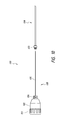
- FIG. 1 illustrates an exemplary balloon catheter that can be used with the methods described herein.
- FIG. 3 illustrates an exemplary embodiment of a needle.
- FIG. 4 illustrates a top view of the needle shown in FIG. 3 having concentric rings to provide a target for laser guidance.
- FIGS. 5-7 illustrate a training model for percutaneous surgical access training.
- FIGS. 8A-8D illustrate a method for laser-guided percutaneous access.
- FIG. 9 illustrates a profile view of exemplary embodiment of a needle assembly that can be used with the methods described herein.
- FIG. 10 illustrates a side view of the trocar needle and a cannula of the needle assembly shown in FIG. 9 .
- FIG. 11 illustrates a perspective view of the trocar needle and the cannula shown in FIG. 10 .
- FIG. 12 illustrates a cross-sectional view of a cap and a proximal portion of an embodiment of a trocar needle.
- FIG. 13A illustrates a cross-sectional view of an embodiment of a trocar needle having a reflective coating plate.
- FIG. 13B illustrates a cross-sectional view of an embodiment of a trocar needle having a dome reflector.
- FIG. 14A illustrates another embodiment of a cap and a trocar needle.
- FIG. 14B illustrates a perspective view of a needle access assembly having the trocar needle shown in FIG. 14A and a cannula.
- FIG. 14C illustrates a side view of the needle access assembly shown in FIG. 14B .
- FIG. 15A illustrates a side view of another embodiment of a needle access assembly having a trocar needle and a cannula.
- FIG. 15B illustrates a distal end view of the trocar needle shown in FIG. 15A .
- FIG. 15C illustrates a proximal end view of the trocar needle shown in FIG. 15A .
- FIG. 15D illustrates a partial cross-section of a proximal portion of the trocar needle shown in FIG. 15A .
- FIG. 16 illustrates a perspective view of an exemplary embodiment of the assembly indicating that the assembly is properly aligned.
- FIG. 17 illustrates a perspective view of the assembly shown in FIG. 16 indicating that the assembly is not properly aligned.
- FIG. 18A illustrates a side view of an exemplary embodiment of a cannula.
- FIG. 18B illustrates an end view of the cannula shown in FIG. 18A .
- FIG. 18C illustrates a perspective view of the cannula shown in FIG. 18A .
- the devices and methods described herein are designed to simplify procedures for percutaneous access and significantly reduce radiation exposure to the surgeon, patient, and staff members. Although the disclosure below is discussed in connection with the kidneys, the methods and devices described herein can be used to obtain access to other structures, lumens, organs, and spaces.
- Placing a needle into the kidney for renal access for stone surgery will be used as an example of this technique.
- similar concepts and principles would also apply to other procedures, such as placing probes into the kidney to treat a renal cancer, placing access into an infected fluid collection for drainage of an abscess, placing tubes into any space to serve as a drain, (i.e., pleural space, peritoneal drain, cholecystectomy drain, bladder drain, lymphocele drain, pericardial space, etc.).
- the patient can be positioned into a prone and split-legged position to allow simultaneous access into the kidney and the urethra.
- the surgeon can place a guide wire into the kidney to allow later insertion of an ureteroscope into the kidney.
- the surgeon can optionally position a dual lumen type catheter in the kidney to allow the placement of a second guide wire, so there can be both a working wire and a safety wire positioned in the kidney.
- the guide wires can be placed into the kidney in a retrograde fashion using no image guidance at all. The two guide wire lengths can be compared to confirm that both wires were correctly positioned in the kidney.
- the working and/or safety guide wires can include one or more of the following features.
- the guide wire can be an angle-tipped guide wire that has a lubricious coating to allow it to slip easily above any ureteral obstruction.
- the guide wire can include one or more features to facilitate visualization.
- the guide wire can be designed to produce a highly echogenic profile allowing it to be easily visualized using ultrasound.
- the shaft may be rounded at the tip to allow easier insertion but have a flattened shape proximal to the tip (e.g., about 1 to 5 cm proximal to the tip of the wire) to allow the wire to be more easily seen under ultrasound guidance.
- the flattened surfaces of the wire may reflect the acoustic beams back at a similar angle to allow the wire to be easily seen under ultrasound. This wire may also be easily seen under very low dose fluoroscopy levels.
- the guide wire can include one or more radiopaque markers to enhance fluoroscopic visualization.
- the guide wire may have interval marks (e.g., placed every one cm) to allow insertion of these wires under endoscopic visualization.
- the wire might be black with white markings identifying the distances.
- the wire could be white with blue markings identifying the length marks. The colors could be any color that would allow easy identification endoscopically and externally.
- the guide wire can include a nitinol core and/or a PTFE coating.
- the guide wire may include a lubricious coating to allow easy insertion.
- the wire could include a retractable square outer sheath through which the guide wire could be placed into the kidney to allow appropriate placement and then the acoustically dense sheath passed over the wire to allow even the tip to be seen easily under ultrasound.
- the guide wire could be etched with an acoustically dense surface to allow the wire to be seen easily under ultrasound guidance.
- the guide wire might be an Amplatz extra stiff type wire that is floppy at both ends to allow the insertion of the flexible ureteroscope without trauma to the ureteroscope or the kidney.
- the guide wire can be a standard 0.035 or 0.038 Teflon-coated guide wire or a lubriciously coated guide wire.
- the surgeon can advance a flexible ureteroscope over the working wire into the ureter using a fluoro-less technique.
- the technique for insertion of the ureteroscope is particularly important to prevent the migration of ureteral stones outside of the ureter, and to facilitate correct positioning of the ureteroscope.
- the ureteroscope will be placed over the working wire and advanced until the ureteroscope tip is in the proximal ureter a distance of 15 to 20 cm in a female and 30-35 cm in a male with normal sized phallus. If recent imaging shows a mid-ureteral stone, the flexible ureteroscope will only be advanced into the distal ureter. If recent imaging shows only a distal ureteral stone, the flexible ureteroscope will be advanced just through the ureteral orifice.
- the actual passage of the ureteroscope may occur in several ways.
- the surgeon advances the ureteroscope tip over the wire while the assistant holds the handle of the ureteroscope and the wire in a steady and fixed position. This allows the surgeon to delicately feel the tactile feedback from the points of resistance as the ureteroscope is advanced over the wire including the urethral sphincter, bladder neck, and ureteral orifice. If resistance is met at the appropriate depth for the ureteral orifice (and the ureteroscope does not progress), the ureteroscope is pulled back 2-3 cm and rotated 90 degrees and another attempt at advancement is made.
- the ureteroscope can be pulled back another 2-3 cm and rotated in the same direction another 90 degrees before another attempt is made. This is repeated until the ureteroscope has returned back to the original starting position. If the ureteroscope has rotated 360 degrees and there has been no passage through the ureteral orifice a Foley will be inserted into the bladder in order to empty the bladder and the process repeated in its entirety.
- the ureteroscope may be passed with the light cord and camera connected so that some subtle visual details may be obtained as the ureteroscope is advanced up the ureter.
- the ureteroscope might be advanced using a “bare naked” technique up the ureter without the use of a safety wire and the ureteroscope used as the safety channel itself.
- normal saline or any other irrigation fluids would be injected under pressure to provide visualization of the important anatomic structures. If the ureteroscope has difficulty engaging the ureteral orifice a guide wire could be inserted into the ureteral orifice to help engage the ureteroscope tip into the ureter and the ureteroscope could then be advanced into the ureter under direct vision.
- the next step in the ureteroscopic-assisted form of the Laser DARRT technique is for the surgeon under direct endoscopic vision to select the desired calix for percutaneous access of the collecting system. After selecting the ideal calix for puncture, the surgeon can determine the optimal access tract using CT, ultrasound, or fluoroscopic guidance.
- Fluoroscopy can optionally be performed with a single pulse or a pulse rate of one pulse per second to visualize the tip of the ureteroscope.
- the ureteroscope is very dense and can be seen easily at even very low mA and kVp settings.
- One pulse per second is significantly lower than the conventional pulse rate, which can be about 25 to about 30 pulses per second.
- ultrasound can be used to map out the pleura, lung, and intra-abdominal organs. Assuming that there are no organs in the way and that the lung is a safe distance away from the puncture site, the needle can be inserted directly under ultrasound guidance into the desired calyx. In some configurations, the needle can be between 14 and 25 gauge, e.g., between about 18 gauge and 20 gauge. In another approach, the needle can be passed into the desired calyx using a “free hand” approach or the needle could be directed using a guide that directs the needle into the desired calyx and is attached to an US probe, CT scanner, or MRI scanner.
- this acoustically dense structure could be a balloon catheter 2 configured for identification under ultrasound.
- the balloon 4 can be inflated with air or ultrasonic contrast material or alternatively with saline to provide a fluid filled target.
- the balloon catheter 2 can be configured for insertion through a flexible ureteroscope channel.
- the balloon catheter shaft 6 can be between about 0.5 F and about 3.3 F. In certain aspects, the shaft can be about 2.2 F.
- the balloon can be made of a strong and expandable polymer, such as silicone, latex, vinyl, Gore-tex®, or any other expandable coverings. The balloon material could be acoustically similar to saline or could be acoustically dense to provide a dense target.
- the balloon can be deflated and removed through the ureteroscope.
- a ureteral access sheath can be placed and then the balloon can be removed with the ureteroscope through the ureteral access sheath.
- the acoustically dense instrument can be a basket catheter.
- FIG. 2 illustrates an exemplary basket catheter 10 designed to create an acoustic interface.
- the basket 12 can be formed from an acoustically dense material or metal, such as Nitinol.
- the basket 12 can form, for example, a large open sphere having an expanded diameter between about 1 mm and about 20 mm. In certain aspects, the expanded diameter can be about 10 mm.
- a small gauge wire can be inserted percutaneously, directly into the basket 12 under ultrasound guidance and then the basket 12 can close over the wire to allow the wire to be pulled into the proximal ureter. Once the small wire is in the proximal ureter, past the stone, a sheath can be inserted over the wire to allow conversion to a larger 0.035 or 0.038 guide wire for subsequent dilation.
- the respirations can be paused by the anesthesiologist after a period of hyperventilation.
- the respirations can be routinely paused during end expiration to move the lungs as far away as possible from the site of needle access.
- the respirations can be held during other parts of the respiratory cycle, for example, during inspiration to move the kidney below the rib.
- fluoroscopy can be used to help direct the needle into the desired calyx instead of using Ultrasound.
- An external instrument can be used to provide an obvious target to assist in targeting the correct calix and positioned on the skin in the path of the fluoroscopy beam such that the beam would align with the tool on the skin and the calyx desired for puncture.
- the surgeon can use a heavy clamp to determine the skin site that will lead to the desired trajectory for PCNL insertion. For example, after using the C-arm to generate an x-ray image and identifying the target location based on the image, the surgeon can mark the target using a clamp or other dense, metal instrument. Use of the instrument to mark the target access position is optional.
- the C-arm 202 can include a laser guide 204 attached to the head of the C-arm beam.
- the laser guide can be configured to facilitate the alignment and insertion of the needle 208 (see FIGS. 8B-8D ) without fluoroscopy or with decreased fluoroscopy and without other image guidance.
- the surgeon can direct the laser guide 204 at the desired needle-insertion angle, for example, in line with the tip of the clamp or other marker on the skin and the ureteroscope inside the desired calix selected for puncture.
- the desired needle-insertion angle can be at least about 0 degrees and/or less than or equal to about 45 degrees relative to the vertical axis L-L, for example, between about 0 degrees and 30 degrees or between 15 degrees and 45 degrees, such as about 30 degrees.
- the needle hub 210 can be aligned with the laser 206 (see FIG. 8B ). Once the needle hub 210 is aligned with the laser 206 , such that the needle hub 210 , needle tip 212 , and ureteroscope tip (not shown) within the kidney 200 form a single point trajectory on the C-arm 202 (see FIG. 8C ), the surgeon can insert the needle 208 without any fluoroscopy activation or with greatly minimized fluoroscopy exposure used only to adjust for slight variations in respiratory excursion (see FIG. 8D ). As shown in FIG.
- the laser 206 can be centered on the hub 210 of the needle, such that the hub 210 is illuminated, ensuring that the needle 208 is inserted at the appropriate trajectory.
- the depth of insertion can be determined based on a pre-operative CT scan or ultrasound measurements where the depth from the skin to the desired calix was measured.
- the desired depth of insertion can be marked on the needle 208 based on the initial images of the target using a mark or removable clip, tape or bracket. This bracket could be attached to the needle reversibly so that the needle would be inserted the desired depth, on the desired trajectory as directed by the laser beam. Once at the desired depth the bracket could be removed.
- the C-arm 202 can be rotated and activated with a single pulse to confirm the depth of the needle.
- the C-arm 202 can be rotated to an angle relative to the vertical axis L-L that is on the opposite side of the vertical axis L-L from the needle insertion angle.
- the angle can be equal to the needle insertion angle.
- the C-arm 202 can be rotated 60 degrees, such that the C-arm 202 is positioned 30 degrees relative to the vertical axis L-L opposite the needle insertion angle.
- the C-arm image intensifier is rotated 30 degrees toward the surgeon, the depth is checked by rotating the image intensifier to 30 degrees away from the surgeon. Additionally or alternatively, the surgeon can judge the depth by watching the ureteroscope image to determine under direct vision when the needle enters the collecting system.
- a wire can be passed from the insertion needle into the collecting system.
- the direct endoscopic vision of the internal tip of the needle can facilitate placement of the guide wire.
- an end of the guide wire can be grasped with a basket passed in a retrograde fashion through the ureteroscope and used to grasp the guide wire as described above.
- This basket can be used to pull the wire down the ureter to establish through and through access out the urethra, or alternatively to establish access only into the proximal ureter beyond the level of any stone or obstruction.
- the basket can include features similar to the basket catheter shown in FIG. 2 .
- a ureteral access sheath can be placed in a retrograde fashion using a completely fluoro-less or minimal fluoroscopy technique. This ureteral access sheath allows the ureteroscope to be re-inserted into the kidney multiple times.
- the guide wire After positioning the guide wire, the guide wire can be converted to a conventional or stiff wire for subsequent dilation of the tract from the skin into the collecting system.
- the skin can be incised with a scalpel to the desired size depending on the size of the sheath employed for dilation.
- the dilating balloon or serial dilation device can be placed at the correct depth using the ureteroscope under direct vision to avoid the use of fluoroscopy.
- the ureteroscope would be used to watch the tip of the balloon catheter enter the collecting system of the kidney and then to position the dilating balloon or serial dilator so that the maximal dilation occurs just inside the edge of the caliceal collecting system.
- the correct depth could be determined on the first dilator if serial dilation was going to be performed and this depth used to insert the subsequent dilators using a bracket, using preplaced markings placed upon the dilators or a mark placed upon the dilators during surgery.
- the balloon can then be inflated to the appropriate pressure for full dilation, and the sheath can be placed into the kidney under direct ureteroscopic visualization.
- fluoroscopy could be used to position the sheath in a conventional manner or using a dramatically reduced fluoroscopic technique.
- the procedure to remove the stone can commence in the standard fashion.
- Flexible and rigid nephroscopy accompanied by use of ultrasound, laser, and/or basketing can be used to remove the stone fragments.
- the kidney can be evaluated by flexible nephroscopy and ureteroscopy to confirm the absence of residual fragments.
- Intraoperative ultrasound can also be used to look for residual stones.
- a single pulse of conventional fluoroscopy can be used to ensure complete fragment removal. This step can be omitted if the surgeon is sure there are no residual fragments following endoscopic renal mapping. Alternatively, renal ultrasound could be used to look for residual fragments.
- the surgeon can remove all the tubes at the conclusion of the procedure.
- the surgeon can place an 8 or 10 French nephrostomy, or a 16, 18, or 22 F council-tipped catheter with a 5 French re-entry catheter inside the renal tract to allow for renal drainage and reentry at a later time if desired.
- These tubes can be placed entirely without image guidance using direct vision by the ureteroscope or with minimal use of single pulse fluoroscopy.
- the ureteral catheter could be placed into the kidney from above while monitoring the position of the proximal end of the catheter using a flexible nephroscope placed through the percutaneous access site.
- a ureteral stent e.g., a multi-length stent between about 22 and about 32 cm long and/or about 6 FR
- a guide wire that was placed into the bladder using an angle tipped guide wire and a 4 FR glide catheter.
- the 0.038 guide wire can be used to insert the stent.
- the length of the stent can be calculated using a novel technique determining the ureteral length using the Pythagorean Theorem where ureter length is calculated by measuring the known coronal ureter length, left to right length, and anterior/posterior length. Alternatively, the length can be estimated by counting the number of axial slices on the CT scan and multiplying by the slice reconstruction and adding 20%.
- the fixed length stent would be placed into the ureter from above and the stent would be advanced until the markings showing the location for the UPJ was identified.
- the distal stent coil in the bladder could be confirmed when the ureteroscope was pulled down into the bladder.
- an end-hole catheter can be placed cystoscopically into the ureter and used to inject diluted contrast into the collecting system of the kidney ranging from 1-99% dilution depending upon the desired density of the contrast.
- the desired calix can be selected using fluoroscopy and any of the previously described techniques mentioned in the preceding description could be used for establishing access into the kidney.
- the C-arm can be rotated laterally between about 20 and about 30 degrees.
- the C-arm, clamp tip, and desired calix can be aligned, and the laser guide can be placed in the center of the needle hub and used to insert the needle in a steady controlled fashion. Using this technique, the surgeon can use his hands with no concern of radiation exposure since the laser guide is used to direct the needle.
- Aspiration of fluid or air can be used to confirm appropriate positioning in the calix.
- a lubricious wire can be fed down the ureter using minimal use of low-dose pulsed or conventional fluoroscopy.
- an ultrasound machine can be used to select percutaneously the appropriate desired posterior calix for access.
- the laser guide can be positioned in line with the access of the ultrasound guide.
- a separate laser guide can be lined up with the axis of the ultrasound guide for insertion of the probe.
- a laser guide can be placed on the CT scanner or CT fluoroscopy machine and the axis of the needle tract can be positioned in line with the laser as directed by the CT scanner.
- the laser guide can be placed on a CT scanner and a special non-ferromagnetic needle can be used for placement using CT fluoroscopy.
- fluoroscopy can be performed with a single pulse or a pulse rate of one pulse per second to visualize the tip of the ureteroscope, needle, and/or guide wire.
- This pulse rate is still significantly lower than the conventional pulse rate, which can be about 25-30 pulses per second.
- a surgeon can reduce the fluoroscopy time from an average of about 6 to about 7 minutes per procedure to less than about one minute.
- the total fluoroscopy time can be between less than or equal to about ten seconds, less than or equal to about three seconds, or less than or equal to about 1 second, thus reducing the risk of cancer dramatically for the patient, surgeon and staff by dramatically reducing the radiation exposure.
- FIG. 3-4 illustrates an exemplary embodiment of a needle assembly 30 configured for use with the methods described above.
- the needle 32 can define a lumen through which a stylet 38 can optionally extend.
- the stylet 38 can include a sharpened distal end to facilitate percutaneous access.
- the needle 32 can define a blunt distal tip 36 to avoid inadvertent injury after removal of the stylet.
- the distal tip of the needle 36 can be sharpened.
- the tip 36 of the needle 32 and/or stylet 38 can be etched to create a prominent acoustic signal on ultrasound.
- at least a portion of the needle 32 proximal to the tip 36 can have a square shape to increase the acoustic prominence of the needle (not shown).
- a proximal portion of the stylet 38 can have a hub 34 .
- the hub 34 can be disc-shaped (see FIG. 3 ) or have a greater depth (e.g., similar to main body 102 of FIG. 11 ).
- an upper surface of the hub 34 can include a number of concentric rings 40 (e.g., two, three, or more) to help the surgeon accurately position the light source (e.g., laser).
- at least a portion of the hub 34 e.g., an outer portion of the hub 34 or the entire hub 34
- can be formed from a non-opaque material e.g., transparent or translucent material.
- an outer portion of the hub 34 can be formed from a transparent material and a central portion of the hub 34 can be formed from an opaque material to help center the laser.
- the hub 34 can include a diameter between about 1 cm and about 5 cm, e.g., about 2 cm.
- the distance between each ring 40 placed on the surface of the needle stylet hub 34 can be at least about 1 mm and/or less than or equal to about 10 mm, e.g., about 5 mm.
- the distance between each ring can be substantially the same or vary.
- the hub 34 can include a crosshatch 42 to help the user identify the central axis of the needle assembly 30 .
- the distance between the central axis C and an end of the crosshatch 42 can be between about 0.5 mm and 5.0 mm, or between about 1.0 mm and about 2.0 mm. In certain aspects, the distance between the central axis C and an end of the crosshatch 42 can be about 2 mm, or about 1.5 mm.
- the needle 32 can include a length of at least about 5 cm, at least or about 10 cm or less than or equal to about 20 cm. In certain aspects, the needle 32 can include a length between about 5 cm and about 20 cm, e.g., about 10 cm, about 15 cm, or about 20 cm. In certain aspects, the needle 32 can be as large as 12 gauge and/or less than or equal to about 25 gauge, e.g., about 18 gauge.
- the needle 32 can define a lumen configured to allow the passage of a wire between about 0.18 gauge and about 0.38 gauge, e.g., about 0.25 gauge.
- the hub 34 can be transparent or translucent and include an opaque channel (not shown).
- the opaque channel can be centrally disposed in the hub 34 .
- An upper surface of the hub 34 can include an opening that would allow the passage of the light source through the opaque channel when the opaque channel is aligned with the light source.
- the opaque channel can be between about 0.1 mm wide and about 2 mm wide. In some embodiments, the opaque channel can have a length between about 1 mm and 5 cm.
- the opaque channel can be lined with one or more reflectors. These reflectors can be constructed from metal, glass, mirrors or any reflective material that can reflect light toward the light source when the light source is not aligned with the opaque channel so that no light enters the transparent or translucent portion of the hub 34 . If the surgeon visualizes the feedback of the light reflected back out of the opaque channel, the surgeon would recognize that the orientation of the needle 32 is not correct.
- the core of the channel could be lined with a wound metal spring that could reflect the light back out when not correctly aligned as described above.
- the needle assembly 30 can include no stylet 38 .
- the distal end 36 of the needle 32 can include a sharpened end, and the hub 34 described above can connected to a proximal end of the needle 32 .
- FIGS. 9 and 9A illustrate an exemplary embodiment of a percutaneous access needle assembly 100 that can be used with the methods described above.
- a laser can facilitate insertion and removal of the needle assembly 100 at the correct position and correct angle.
- the main housing 102 of the needle assembly 100 can light up to indicate proper alignment with a light source (see FIG. 9 ).
- Use of the light source and needle assembly 100 to position the needle can reduce the total amount of fluoroscopy time by at least 50%.
- the needle access assembly 100 can include a trocar needle 108 axially movable through a cannula 104 (see FIGS. 18A-18C ).
- the trocar needle 108 can include a main housing 102 and a needle 105 extending from the main housing 102 .
- the needle 105 which is sharpened to allow for easy insertion, can optionally be detached from the trocar needle 108 .
- the needle 105 can connect directly or indirectly to the main housing 102 using a snap fit, friction fit, screw fit, adhesive, or other suitable connection.
- the trocar 108 can optionally include an engagement feature 106 (see FIGS.
- the needle assembly 100 can include a luer connector at a distal end of the main body 102 .
- the luer connector 106 of the needle assembly 100 can engage a corresponding luer connector positioned at a proximal end of the cannula 104 .
- Other connections are also imaginable, such as screw fit, a friction fit, a snap fit, or otherwise.
- the trocar 108 can include a cap 101 through which a laser or other light source can be shined through an opening 110 to provide guidance for percutaneous access.
- the cap 101 can be opaque and can have the narrow, centrally disposed opening 110 extending through the cap 101 .
- the opening 110 can have a diameter that is less than a diameter of the main body 102 (e.g., less than about 50%, less than about 40%, less than about 30%, less than about 20%, less than about 10%, or values in between).
- the opening 110 can be optionally filled with a transparent material.
- the cap 101 can optionally include a concentric circle pattern similar to the pattern described in connection with FIG. 4 to facilitate the positioning of the laser.
- the main body 102 can include a diameter of at least about 1 inch, at least about 2 inches, or preferably at least about 3 inches.
- the main body 102 can be constructed from an opaque material, and the user can rely on alignment between the light source and opening 110 for visual indication of proper alignment.
- the main body 102 can be constructed from a transparent or translucent material so that users can visualize the light source shining through the main body 102 . Since the cap 101 is opaque, the main body 102 will only illuminate if the laser is aligned with the opening 110 . This ensures that that the main body 102 is not illuminated when the laser enters the main body 102 but at an incorrect angle.
- the cap 101 can removably engage the main body 102 .
- the cap 101 can threadably engage the main body 102 , such that the cap 101 fits into (see FIG. 12 ) and/or surrounds (see FIGS. 14A-14C ) the main body 102 .
- the cap 101 can engage the main body 102 using a snap fit (not shown) such that the cap 101 fits into and/or surrounds the main body 102 .
- the cap 101 and main body 102 can be integrally formed.
- the main body 102 of the trocar 108 can optionally include a light enhancement feature for propagating light.
- a reflective plate, reflecting coating, otherwise reflective surface 111 can be provided within an interior space of the main body 102 .
- a dome reflector 112 can be positioned within the main housing 102 .
- the light enhancement feature can propagate light 116 such that there is clear visual indication of proper alignment.
- FIG. 17 when the needle access assembly 100 is not properly aligned with the light source 114 , little or no light can be seen from the main housing 102 .
- the needle access assembly 100 can include a camera to provide direct visualization during insertion.
- the needle access assembly 100 can include sensors in a 3D array to provide real time data on 3D movement of the needle access assembly 100 .
- FIGS. 5-7 illustrate a training model 50 for training users how to obtain percutaneous access using the above-described technique.
- the model 50 can include one or more layers 52 designed to replicate the organs, muscle, fat, and skin.
- FIGS. 5-7 specifically illustrate a model 50 for the kidney collecting system, but similar materials can be used to construct a model for other areas of the body.
- the model 50 can include one or more layers designed to replicate the skin.
- the skin layers can include, but are not limited to, carpet padding, plastic, or silicone.
- the deep muscles and perinephric fat can be replicated using gelatin, silicone, or any polymer or substance that will permit shaping into the desired shape.
- the model collecting system 56 can be replicated using a latex or any type of glove.
- the fingers 58 can be tied off to create the calices, and tape can be applied to the innermost portions of the fingers to create the narrowing of the infundibula.
- the palm of the glove 60 can be narrowed by tying or using tape to create a renal pelvis.
- the palm of the glove 60 can be connected to a penrose drain 62 to establish the ureter.
- the model kidney 54 can be replicated by forming reniform shape from a gelatin, soft plastic, silicone, or other soft material.
- the kidney material can be made of clear material to allow an observer to determine if the trainee had placed the needle into the appropriate calix by visual inspection from underneath a glass surface.
- the model 50 could include a small camera on the inside to simulate the image provided by the ureteroscope and to allow the trainee to learn how the internal image may assist in correct placement of the needle.
- the layers 52 can be mounted on a surface constructed from a clear material, for example, plexiglass.
- a clear material for example, plexiglass.
- One or more holes can be formed in the clear surface. Each of the holes can receive a bolt or other structure to secure and align each of the layers to the clear surface.
- the model can be positioned on the cut out portion of the fluoroscopy table, so the observer can easily see if the needle had been placed into the appropriate calix by direct observation.
- An open-ended catheter can be used to create the contrast used for injection if the training would like to focus on learning the fluoroscopy guided laser DARRT technique.
- the terms “approximately,” “about,” and “substantially” as used herein represent an amount close to the stated amount that still performs a desired function or achieves a desired result.
- the terms “approximately”, “about”, and “substantially” may refer to an amount that is within less than 10% of, within less than 5% of, within less than 1% of, within less than 0.1% of, and within less than 0.01% of the stated amount.
- any methods disclosed herein need not be performed in the order recited.
- the methods disclosed herein include certain actions taken by a practitioner; however, they can also include any third-party instruction of those actions, either expressly or by implication.
- actions such as “aligning a needle with a light source” include “instructing alignment of a needle and a light source.”
- a needle access device configured for insertion into a patient with reduced fluoroscopy, the device comprising:
- the hub portion further comprises a luer connector configured to connect to a cannula.
- a method of obtaining percutaneous needle access :
- Embodiment 17 further comprising delivering an instrument through the ureteroscope, the instrument configured to facilitate the insertion of the needle through the selected calix.
- Embodiment 20 The method of Embodiment 18 or 19, wherein the instrument is a balloon catheter.
- Embodiment 24 The method of Embodiment 23, wherein illuminating the hub portion of the needle access device comprises reflecting the light source from a reflective surface within the hub portion.
Landscapes
- Health & Medical Sciences (AREA)
- Life Sciences & Earth Sciences (AREA)
- Surgery (AREA)
- Engineering & Computer Science (AREA)
- Heart & Thoracic Surgery (AREA)
- Biomedical Technology (AREA)
- General Health & Medical Sciences (AREA)
- Animal Behavior & Ethology (AREA)
- Veterinary Medicine (AREA)
- Public Health (AREA)
- Medical Informatics (AREA)
- Molecular Biology (AREA)
- Pathology (AREA)
- Nuclear Medicine, Radiotherapy & Molecular Imaging (AREA)
- Biophysics (AREA)
- Physics & Mathematics (AREA)
- Radiology & Medical Imaging (AREA)
- Optics & Photonics (AREA)
- Anesthesiology (AREA)
- Hematology (AREA)
- Pulmonology (AREA)
- Human Computer Interaction (AREA)
- Oral & Maxillofacial Surgery (AREA)
- High Energy & Nuclear Physics (AREA)
- Child & Adolescent Psychology (AREA)
- Gastroenterology & Hepatology (AREA)
- Robotics (AREA)
- Surgical Instruments (AREA)
- Ultra Sonic Daignosis Equipment (AREA)
- Urology & Nephrology (AREA)
- Laser Surgery Devices (AREA)
Priority Applications (5)
| Application Number | Priority Date | Filing Date | Title |
|---|---|---|---|
| US14/295,224 US8998943B2 (en) | 2013-06-03 | 2014-06-03 | Methods and apparatuses for fluoro-less or near fluoro-less percutaneous surgery access |
| US14/678,696 US9351758B2 (en) | 2013-06-03 | 2015-04-03 | Methods and apparatuses for fluoro-less or near fluoro-less percutaneous surgery access |
| US15/145,631 US10085767B2 (en) | 2013-06-03 | 2016-05-03 | Methods and apparatuses for fluoro-less or near fluoro-less percutaneous surgery access |
| US15/963,542 US10792067B2 (en) | 2013-06-03 | 2018-04-26 | Methods and apparatuses for fluoro-less or near fluoro-less percutaneous surgery access |
| US16/110,245 US10932816B2 (en) | 2013-06-03 | 2018-08-23 | Methods and apparatuses for fluoro-less or near fluoro-less percutaneous surgery access |
Applications Claiming Priority (3)
| Application Number | Priority Date | Filing Date | Title |
|---|---|---|---|
| US201361830585P | 2013-06-03 | 2013-06-03 | |
| US201361902090P | 2013-11-08 | 2013-11-08 | |
| US14/295,224 US8998943B2 (en) | 2013-06-03 | 2014-06-03 | Methods and apparatuses for fluoro-less or near fluoro-less percutaneous surgery access |
Related Parent Applications (1)
| Application Number | Title | Priority Date | Filing Date |
|---|---|---|---|
| US15/271,414 Continuation-In-Part US10405943B2 (en) | 2013-06-03 | 2016-09-21 | Kit and method for reduced radiation procedures |
Related Child Applications (1)
| Application Number | Title | Priority Date | Filing Date |
|---|---|---|---|
| US14/678,696 Continuation US9351758B2 (en) | 2013-06-03 | 2015-04-03 | Methods and apparatuses for fluoro-less or near fluoro-less percutaneous surgery access |
Publications (2)
| Publication Number | Publication Date |
|---|---|
| US20140357987A1 US20140357987A1 (en) | 2014-12-04 |
| US8998943B2 true US8998943B2 (en) | 2015-04-07 |
Family
ID=51985885
Family Applications (6)
| Application Number | Title | Priority Date | Filing Date |
|---|---|---|---|
| US14/295,224 Active - Reinstated US8998943B2 (en) | 2013-06-03 | 2014-06-03 | Methods and apparatuses for fluoro-less or near fluoro-less percutaneous surgery access |
| US14/295,148 Active - Reinstated US9095361B2 (en) | 2013-06-03 | 2014-06-03 | Methods and apparatuses for fluoro-less or near fluoro-less percutaneous surgery access |
| US14/678,696 Active - Reinstated US9351758B2 (en) | 2013-06-03 | 2015-04-03 | Methods and apparatuses for fluoro-less or near fluoro-less percutaneous surgery access |
| US14/802,753 Expired - Fee Related US9918739B2 (en) | 2013-06-03 | 2015-07-17 | Methods and apparatuses for fluoro-less or near fluoro-less percutaneous surgery access |
| US15/145,631 Active - Reinstated 2034-06-27 US10085767B2 (en) | 2013-06-03 | 2016-05-03 | Methods and apparatuses for fluoro-less or near fluoro-less percutaneous surgery access |
| US16/110,245 Active 2034-07-12 US10932816B2 (en) | 2013-06-03 | 2018-08-23 | Methods and apparatuses for fluoro-less or near fluoro-less percutaneous surgery access |
Family Applications After (5)
| Application Number | Title | Priority Date | Filing Date |
|---|---|---|---|
| US14/295,148 Active - Reinstated US9095361B2 (en) | 2013-06-03 | 2014-06-03 | Methods and apparatuses for fluoro-less or near fluoro-less percutaneous surgery access |
| US14/678,696 Active - Reinstated US9351758B2 (en) | 2013-06-03 | 2015-04-03 | Methods and apparatuses for fluoro-less or near fluoro-less percutaneous surgery access |
| US14/802,753 Expired - Fee Related US9918739B2 (en) | 2013-06-03 | 2015-07-17 | Methods and apparatuses for fluoro-less or near fluoro-less percutaneous surgery access |
| US15/145,631 Active - Reinstated 2034-06-27 US10085767B2 (en) | 2013-06-03 | 2016-05-03 | Methods and apparatuses for fluoro-less or near fluoro-less percutaneous surgery access |
| US16/110,245 Active 2034-07-12 US10932816B2 (en) | 2013-06-03 | 2018-08-23 | Methods and apparatuses for fluoro-less or near fluoro-less percutaneous surgery access |
Country Status (6)
| Country | Link |
|---|---|
| US (6) | US8998943B2 (de) |
| EP (2) | EP3398543A1 (de) |
| JP (1) | JP2016526958A (de) |
| CA (1) | CA2914359A1 (de) |
| TR (1) | TR201807093T4 (de) |
| WO (1) | WO2014197502A1 (de) |
Cited By (5)
| Publication number | Priority date | Publication date | Assignee | Title |
|---|---|---|---|---|
| US20170156800A1 (en) * | 2014-03-17 | 2017-06-08 | Roy Anthony Brown | Surgical Targeting Systems and Methods |
| US9918739B2 (en) | 2013-06-03 | 2018-03-20 | Faculty Physicians And Surgeons Of Loma Linda Univ | Methods and apparatuses for fluoro-less or near fluoro-less percutaneous surgery access |
| US10405943B2 (en) | 2015-09-22 | 2019-09-10 | Faculty Physicians And Surgeons Of Loma Linda University School Of Medicine | Kit and method for reduced radiation procedures |
| US10792067B2 (en) | 2013-06-03 | 2020-10-06 | Faculty Physicians And Surgeons Of Loma Linda University Of Medicine | Methods and apparatuses for fluoro-less or near fluoro-less percutaneous surgery access |
| US11311311B2 (en) | 2016-01-08 | 2022-04-26 | Boston Scientific Scimed, Inc. | Devices and methods for guiding a surgical instrument |
Families Citing this family (20)
| Publication number | Priority date | Publication date | Assignee | Title |
|---|---|---|---|---|
| CN104758034A (zh) * | 2015-01-23 | 2015-07-08 | 倪家骧 | 一种针体带激光定位灯的穿刺针 |
| CN106491216B (zh) * | 2016-10-28 | 2019-06-28 | 苏州朗开医疗技术有限公司 | 一种诊断体内目标对象定位系统和医疗定位系统 |
| CN110418596B (zh) * | 2017-03-28 | 2021-12-24 | 富士胶片株式会社 | 测量辅助装置、内窥镜系统及处理器 |
| JP6666519B2 (ja) | 2017-03-28 | 2020-03-13 | 富士フイルム株式会社 | 計測支援装置、内視鏡システム、及びプロセッサ |
| WO2018200799A1 (en) * | 2017-04-26 | 2018-11-01 | Faculty Physicians And Surgeons Of Loma Linda University School Of Medicine | Methods and apparatuses for fluoro-less or near fluoro-less percutaneous surgery access |
| US10667869B2 (en) * | 2017-05-17 | 2020-06-02 | General Electric Company | Guidance system for needle procedures |
| US10624669B2 (en) * | 2017-06-23 | 2020-04-21 | Wells Mangrum | Image-guided drainage of abscesses |
| CN111031946A (zh) | 2017-08-09 | 2020-04-17 | 爱尔康公司 | 自行照明的显微外科插管装置 |
| US12023463B2 (en) * | 2018-01-02 | 2024-07-02 | Cerner Innovation, Inc. | Clinical notifications |
| CN108309451B (zh) * | 2018-02-05 | 2020-12-29 | 吴博远 | 一种用于基层医院的颅脑病灶导航系统 |
| DE102018215599B4 (de) | 2018-09-13 | 2021-07-15 | Siemens Healthcare Gmbh | Ausrichtelement zum Ausrichten einer Nadelführung; Ausrichtanordnung; Führungsanordnung; Behandlungsanordnung sowie Verfahren |
| CN109173085A (zh) * | 2018-09-20 | 2019-01-11 | 成都真实维度科技有限公司 | 一种用于提高粒子植入针轴向精度的限位装置 |
| CN109481018A (zh) | 2018-12-29 | 2019-03-19 | 上海联影医疗科技有限公司 | 一种应用在医疗操作中的导航设备及方法 |
| DE102019206825B3 (de) | 2019-05-10 | 2020-07-02 | Siemens Healthcare Gmbh | Positionierungseinheit mit mehreren Anzeigemitteln zum Führen einer Nadel; Positionierungssystem sowie Verfahren |
| CN110215265B (zh) * | 2019-06-13 | 2020-10-30 | 中国人民解放军陆军军医大学第二附属医院 | 一种腹腔镜肝切除手术用套管穿刺针 |
| KR20220123273A (ko) | 2019-12-31 | 2022-09-06 | 아우리스 헬스, 인코포레이티드 | 해부학적 특징부 식별 및 표적설정 |
| US11737663B2 (en) | 2020-03-30 | 2023-08-29 | Auris Health, Inc. | Target anatomical feature localization |
| KR102399973B1 (ko) * | 2021-04-05 | 2022-05-20 | 서울대학교병원 | 레이저를 이용한 무침습 척추 수술 유도 시스템 |
| WO2022272216A1 (en) * | 2021-06-21 | 2022-12-29 | Varian Medical Systems, Inc. | Ablation probes with guidance indicators to support location and direction guidance systems |
| US20240261033A1 (en) * | 2023-02-02 | 2024-08-08 | Varian Medical Systems, Inc. | Ablation probes with guidance indicators to support location and direction guidance systems |
Citations (30)
| Publication number | Priority date | Publication date | Assignee | Title |
|---|---|---|---|---|
| US3801205A (en) * | 1972-04-06 | 1974-04-02 | Pulfer Ag | Process and device for the survey alignment with a laser beam |
| US4319839A (en) * | 1980-03-27 | 1982-03-16 | The United States Of America As Represented By The Secretary Of The Air Force | Beam alignment system |
| US4651732A (en) * | 1983-03-17 | 1987-03-24 | Frederick Philip R | Three-dimensional light guidance system for invasive procedures |
| US4674870A (en) * | 1985-10-18 | 1987-06-23 | Spectra-Physics, Inc. | Laser alignment system with modulated field |
| US5810841A (en) * | 1997-01-22 | 1998-09-22 | Minrad Inc. | Energy guided apparatus and method with indication of alignment |
| US6021342A (en) | 1997-06-30 | 2000-02-01 | Neorad A/S | Apparatus for assisting percutaneous computed tomography-guided surgical activity |
| US6041249A (en) * | 1997-03-13 | 2000-03-21 | Siemens Aktiengesellschaft | Device for making a guide path for an instrument on a patient |
| US6096049A (en) * | 1998-07-27 | 2000-08-01 | Minrad Inc. | Light guiding device and method |
| US6443960B1 (en) * | 2000-11-24 | 2002-09-03 | Neorad A/S | Apparatus for light beam guided biopsy |
| US20030120154A1 (en) * | 2001-11-28 | 2003-06-26 | Frank Sauer | Method and apparatus for ultrasound guidance of needle biopsies |
| US6605095B2 (en) * | 2000-06-13 | 2003-08-12 | Sdgi Holdings, Inc. | Percutaneous needle alignment system and associated method |
| US6607477B1 (en) | 1998-02-16 | 2003-08-19 | Wallace A. Longton | Graduated intraluminal catheter and methods of use thereof |
| US6689142B1 (en) * | 1999-04-26 | 2004-02-10 | Scimed Life Systems, Inc. | Apparatus and methods for guiding a needle |
| US6810595B2 (en) * | 2002-12-24 | 2004-11-02 | Wing-Sheung Chan | Laser angle guide assembly for computed tomography and method for the same |
| US20050256451A1 (en) * | 2002-09-17 | 2005-11-17 | Transoma Medical, Inc. | Vascular access port with needle detector |
| US20070100234A1 (en) * | 2005-10-27 | 2007-05-03 | Arenson Jerome S | Methods and systems for tracking instruments in fluoroscopy |
| US20070100299A1 (en) | 2002-06-27 | 2007-05-03 | Anders Magnusson | Drainage catheter |
| US20080146915A1 (en) * | 2006-10-19 | 2008-06-19 | Mcmorrow Gerald | Systems and methods for visualizing a cannula trajectory |
| US20080146939A1 (en) * | 2002-06-07 | 2008-06-19 | Mcmorrow Gerald | Apparatus and method for image guided insertion and removal of a cannula or needle |
| US7621868B2 (en) * | 2004-01-14 | 2009-11-24 | Precision Optics Corporation | Convergence optics for stereoscopic imaging systems |
| US20110172520A1 (en) | 2007-05-15 | 2011-07-14 | Cook Medical Technologies Llc | Multifilar cable catheter |
| US20120022508A1 (en) * | 2010-07-22 | 2012-01-26 | Patrick Gross | Method and orientation device for marking a predetermined guide path of a medical instrument |
| US20120022504A1 (en) * | 2008-09-11 | 2012-01-26 | Syneron Medical Ltd. | Device, apparatus, and method of adipose tissue treatment |
| US8162852B2 (en) * | 2008-10-23 | 2012-04-24 | Devicor Medical Products, Inc. | Methods for medical device alignment |
| US20120123204A1 (en) | 2010-11-15 | 2012-05-17 | Jason Benjamin Wynberg | Percutaneous Renal Access System |
| US20120316500A1 (en) | 2010-02-08 | 2012-12-13 | Access Scientific, Inc. | Access device |
| US20130018254A1 (en) * | 2010-03-19 | 2013-01-17 | Quickvein, Inc. | Apparatus and methods for imaging blood vessels |
| US8454586B2 (en) * | 2006-03-13 | 2013-06-04 | Bruno Anastasie | Laser instrument for vascular occlusion, in particular for intravenous treatment, and for perforation or detersion of tissue |
| US20140107473A1 (en) | 2012-10-17 | 2014-04-17 | Cincinnati Children's Hospital Medical Center | Laser Guidance System for Interventions |
| US8715233B2 (en) * | 2011-12-21 | 2014-05-06 | The Board Of Trustees Of The Leland Stanford Junior University | Assistive method and visual-aid device for vascular needle insertion |
Family Cites Families (5)
| Publication number | Priority date | Publication date | Assignee | Title |
|---|---|---|---|---|
| CH671873A5 (de) * | 1985-10-03 | 1989-10-13 | Synthes Ag | |
| WO1993015683A1 (en) * | 1992-02-07 | 1993-08-19 | Medical Device Technologies, Inc. | Targeting guidance device for localization needle assemblies |
| US5409000A (en) * | 1993-09-14 | 1995-04-25 | Cardiac Pathways Corporation | Endocardial mapping and ablation system utilizing separately controlled steerable ablation catheter with ultrasonic imaging capabilities and method |
| WO2008089537A1 (en) * | 2007-01-22 | 2008-07-31 | Baylis Medical Company Inc. | Positioning tool for positioning an instrument at a treatment site |
| EP3398543A1 (de) | 2013-06-03 | 2018-11-07 | Faculty Physicians and Surgeons of Loma Linda University School of Medicine | Vorrichtungen für fluorlosen oder fluorarmen perkutanen chirurgischen zugriff |
-
2014
- 2014-06-03 EP EP18161332.4A patent/EP3398543A1/de not_active Withdrawn
- 2014-06-03 US US14/295,224 patent/US8998943B2/en active Active - Reinstated
- 2014-06-03 JP JP2016518415A patent/JP2016526958A/ja active Pending
- 2014-06-03 CA CA2914359A patent/CA2914359A1/en not_active Abandoned
- 2014-06-03 EP EP14807718.3A patent/EP3003181B1/de not_active Not-in-force
- 2014-06-03 US US14/295,148 patent/US9095361B2/en active Active - Reinstated
- 2014-06-03 WO PCT/US2014/040744 patent/WO2014197502A1/en not_active Ceased
- 2014-06-03 TR TR2018/07093T patent/TR201807093T4/tr unknown
-
2015
- 2015-04-03 US US14/678,696 patent/US9351758B2/en active Active - Reinstated
- 2015-07-17 US US14/802,753 patent/US9918739B2/en not_active Expired - Fee Related
-
2016
- 2016-05-03 US US15/145,631 patent/US10085767B2/en active Active - Reinstated
-
2018
- 2018-08-23 US US16/110,245 patent/US10932816B2/en active Active
Patent Citations (32)
| Publication number | Priority date | Publication date | Assignee | Title |
|---|---|---|---|---|
| US3801205A (en) * | 1972-04-06 | 1974-04-02 | Pulfer Ag | Process and device for the survey alignment with a laser beam |
| US4319839A (en) * | 1980-03-27 | 1982-03-16 | The United States Of America As Represented By The Secretary Of The Air Force | Beam alignment system |
| US4651732A (en) * | 1983-03-17 | 1987-03-24 | Frederick Philip R | Three-dimensional light guidance system for invasive procedures |
| US4674870A (en) * | 1985-10-18 | 1987-06-23 | Spectra-Physics, Inc. | Laser alignment system with modulated field |
| US5810841A (en) * | 1997-01-22 | 1998-09-22 | Minrad Inc. | Energy guided apparatus and method with indication of alignment |
| US6041249A (en) * | 1997-03-13 | 2000-03-21 | Siemens Aktiengesellschaft | Device for making a guide path for an instrument on a patient |
| US6021342A (en) | 1997-06-30 | 2000-02-01 | Neorad A/S | Apparatus for assisting percutaneous computed tomography-guided surgical activity |
| US6607477B1 (en) | 1998-02-16 | 2003-08-19 | Wallace A. Longton | Graduated intraluminal catheter and methods of use thereof |
| US6096049A (en) * | 1998-07-27 | 2000-08-01 | Minrad Inc. | Light guiding device and method |
| US7204826B2 (en) | 1999-04-26 | 2007-04-17 | Boston Scientific Scimed, Inc. | Apparatus and methods for guiding a needle |
| US6689142B1 (en) * | 1999-04-26 | 2004-02-10 | Scimed Life Systems, Inc. | Apparatus and methods for guiding a needle |
| US20040106934A1 (en) * | 2000-06-13 | 2004-06-03 | Sdgi Holdings, Inc. | Percutaneous Needle Alignment System |
| US6605095B2 (en) * | 2000-06-13 | 2003-08-12 | Sdgi Holdings, Inc. | Percutaneous needle alignment system and associated method |
| US6443960B1 (en) * | 2000-11-24 | 2002-09-03 | Neorad A/S | Apparatus for light beam guided biopsy |
| US20030120154A1 (en) * | 2001-11-28 | 2003-06-26 | Frank Sauer | Method and apparatus for ultrasound guidance of needle biopsies |
| US20080146939A1 (en) * | 2002-06-07 | 2008-06-19 | Mcmorrow Gerald | Apparatus and method for image guided insertion and removal of a cannula or needle |
| US20070100299A1 (en) | 2002-06-27 | 2007-05-03 | Anders Magnusson | Drainage catheter |
| US20050256451A1 (en) * | 2002-09-17 | 2005-11-17 | Transoma Medical, Inc. | Vascular access port with needle detector |
| US6810595B2 (en) * | 2002-12-24 | 2004-11-02 | Wing-Sheung Chan | Laser angle guide assembly for computed tomography and method for the same |
| US7621868B2 (en) * | 2004-01-14 | 2009-11-24 | Precision Optics Corporation | Convergence optics for stereoscopic imaging systems |
| US20070100234A1 (en) * | 2005-10-27 | 2007-05-03 | Arenson Jerome S | Methods and systems for tracking instruments in fluoroscopy |
| US8454586B2 (en) * | 2006-03-13 | 2013-06-04 | Bruno Anastasie | Laser instrument for vascular occlusion, in particular for intravenous treatment, and for perforation or detersion of tissue |
| US20080146915A1 (en) * | 2006-10-19 | 2008-06-19 | Mcmorrow Gerald | Systems and methods for visualizing a cannula trajectory |
| US20110172520A1 (en) | 2007-05-15 | 2011-07-14 | Cook Medical Technologies Llc | Multifilar cable catheter |
| US20120022504A1 (en) * | 2008-09-11 | 2012-01-26 | Syneron Medical Ltd. | Device, apparatus, and method of adipose tissue treatment |
| US8162852B2 (en) * | 2008-10-23 | 2012-04-24 | Devicor Medical Products, Inc. | Methods for medical device alignment |
| US20120316500A1 (en) | 2010-02-08 | 2012-12-13 | Access Scientific, Inc. | Access device |
| US20130018254A1 (en) * | 2010-03-19 | 2013-01-17 | Quickvein, Inc. | Apparatus and methods for imaging blood vessels |
| US20120022508A1 (en) * | 2010-07-22 | 2012-01-26 | Patrick Gross | Method and orientation device for marking a predetermined guide path of a medical instrument |
| US20120123204A1 (en) | 2010-11-15 | 2012-05-17 | Jason Benjamin Wynberg | Percutaneous Renal Access System |
| US8715233B2 (en) * | 2011-12-21 | 2014-05-06 | The Board Of Trustees Of The Leland Stanford Junior University | Assistive method and visual-aid device for vascular needle insertion |
| US20140107473A1 (en) | 2012-10-17 | 2014-04-17 | Cincinnati Children's Hospital Medical Center | Laser Guidance System for Interventions |
Non-Patent Citations (12)
| Title |
|---|
| Bilen, et al.: "Laser-Assisted Fluoroscopic Puncture: A New Technique for Accessing the Kidney", Journal of Endourology, vol. 17, No. 7, Sep. 2003. |
| Blair, et al.: "Reduced Fluoroscopy Protocol for Percutaneous Nephrostolithotomy: Feasibility, Outcomes and Effects on Fluoroscopy Time", The Journal of Urology, vol. 190, Dec. 2013, pp. 2112-2116. |
| Brisbane, et al.: "Fluoro-less Ureteral Stent Placement Following Uncomplicated Ureteroscopic Stone Removal: A Feasibility Study", Urology 80 (4), 2012, pp. 766-770. |
| Greene, et al.: "Comparison of a Reduced Radiation Fluoroscopy Protocol to Conventional Fluoroscopy during Uncomplicated Ureteroscopy", Urology 79 (2), 2011, pp. 287-290. |
| Hsi, et al.: Fluoroless Ureteroscopy: Zero-Dose Fluoroscopy During Ureteroscopic Treatment of Urinary-Tract Calculi, Journal of Endourology, vol. 27, No. 4, Apr. 2013, pp. 432-437. |
| International Search Report and Written Opinion, re PCT App. No. PCT/US2014/040744, mailed Oct. 12, 2014. |
| Ko, et al.: "C-Arm Laser Positioning Device to Facilitate Percutaneous Renal Access", Surgeon's Workshop, Urology 70 (2), 2007. |
| Kokorowski, et al.: Prospective Systematic Intervention to Reduce Patient Exposure to Radiation During Pediatric Ureteroscopy, The Journal of Urology, vol. 190, 1747-1478, Oct. 2013. |
| Krupp, et al.: "Fluoroscopic Organ and Tissue-Specific Radiation Exposure by Sex and Body Mass Index During Ureteroscopy", Journal of Endourology, vol. 24, No. 7, Jul. 2010, pp. 1067-1073. |
| Nguyen, et al.: "In Automated Fluoroscopy Settings, Does Shielding Affect Radiation Exposure to Surrounding Unshielded Tissues?", Journal of Endourology, vol. 26, No. 11, Nov. 2012. |
| Smith, et al.: "Radiation Exposure During Continuous and Pulsed Fluoroscopy", Journal of Endourology, vol. 27, No. 3, Mar. 2013, pp. 384-388. |
| U.S. Appl. No. 14/295,148 and its entire file history, filed Jun. 3, 2014, Baldwin. |
Cited By (8)
| Publication number | Priority date | Publication date | Assignee | Title |
|---|---|---|---|---|
| US9918739B2 (en) | 2013-06-03 | 2018-03-20 | Faculty Physicians And Surgeons Of Loma Linda Univ | Methods and apparatuses for fluoro-less or near fluoro-less percutaneous surgery access |
| US10085767B2 (en) | 2013-06-03 | 2018-10-02 | Faculty Physicians And Surgeons Of Loma Linda University | Methods and apparatuses for fluoro-less or near fluoro-less percutaneous surgery access |
| US10792067B2 (en) | 2013-06-03 | 2020-10-06 | Faculty Physicians And Surgeons Of Loma Linda University Of Medicine | Methods and apparatuses for fluoro-less or near fluoro-less percutaneous surgery access |
| US10932816B2 (en) | 2013-06-03 | 2021-03-02 | Faculty Physicians And Surgeons Of Loma Linda University School Of Medicine | Methods and apparatuses for fluoro-less or near fluoro-less percutaneous surgery access |
| US20170156800A1 (en) * | 2014-03-17 | 2017-06-08 | Roy Anthony Brown | Surgical Targeting Systems and Methods |
| US10405943B2 (en) | 2015-09-22 | 2019-09-10 | Faculty Physicians And Surgeons Of Loma Linda University School Of Medicine | Kit and method for reduced radiation procedures |
| US11311311B2 (en) | 2016-01-08 | 2022-04-26 | Boston Scientific Scimed, Inc. | Devices and methods for guiding a surgical instrument |
| US12539140B2 (en) | 2016-01-08 | 2026-02-03 | Boston Scientific Scimed, Inc. | Devices and methods for guiding a surgical instrument |
Also Published As
| Publication number | Publication date |
|---|---|
| US20150320440A1 (en) | 2015-11-12 |
| US20150272701A1 (en) | 2015-10-01 |
| US20140357987A1 (en) | 2014-12-04 |
| US9918739B2 (en) | 2018-03-20 |
| EP3398543A1 (de) | 2018-11-07 |
| WO2014197502A1 (en) | 2014-12-11 |
| US9351758B2 (en) | 2016-05-31 |
| US9095361B2 (en) | 2015-08-04 |
| US10932816B2 (en) | 2021-03-02 |
| EP3003181B1 (de) | 2018-02-21 |
| US20140357986A1 (en) | 2014-12-04 |
| EP3003181A4 (de) | 2017-01-11 |
| US10085767B2 (en) | 2018-10-02 |
| US20160310165A1 (en) | 2016-10-27 |
| US20190133637A1 (en) | 2019-05-09 |
| CA2914359A1 (en) | 2014-12-11 |
| EP3003181A1 (de) | 2016-04-13 |
| JP2016526958A (ja) | 2016-09-08 |
| TR201807093T4 (tr) | 2018-06-21 |
Similar Documents
| Publication | Publication Date | Title |
|---|---|---|
| US10932816B2 (en) | Methods and apparatuses for fluoro-less or near fluoro-less percutaneous surgery access | |
| US10792067B2 (en) | Methods and apparatuses for fluoro-less or near fluoro-less percutaneous surgery access | |
| US10405943B2 (en) | Kit and method for reduced radiation procedures | |
| JP7391926B2 (ja) | 患者内の解剖学的構造の画像誘導ナビゲーションをもたらす装置 | |
| JP6283128B2 (ja) | 基準マーカ留置のためのねじ駆動式ハンドルおよびシステム | |
| JP5746800B2 (ja) | 入れ子カニューレの開始アライメント | |
| CN111093536A (zh) | 具有穿透特征部的传感器引导的器械 | |
| WO2018200799A1 (en) | Methods and apparatuses for fluoro-less or near fluoro-less percutaneous surgery access | |
| JP7604747B2 (ja) | エネルギー伝達のための内視鏡システム | |
| JP2020515342A (ja) | コアワイヤを含有する光学管を備えるガイドワイヤ | |
| US20060020199A1 (en) | Urethral radiation treatment system and method | |
| CN117999040A (zh) | 用于基于实时图像的装置定位的系统和方法 | |
| Ganpule et al. | Percutaneous Nephrolithomy: Access and Instrumentation | |
| IL295450A (en) | Tracheotomy | |
| Sabnis et al. | Urology Instrumentation-A Comprehensive Guide | |
| CN119655881A (zh) | 带有虚拟照明以跟踪装备有传感器的医疗器械的移动的3d虚拟图像 | |
| US20150359562A1 (en) | Arthroscopic joint surgery device and method of use |
Legal Events
| Date | Code | Title | Description |
|---|---|---|---|
| AS | Assignment |
Owner name: LOMA LINDA UNIVERSITY, CALIFORNIA Free format text: ASSIGNMENT OF ASSIGNORS INTEREST;ASSIGNORS:YEO, ALEXANDER;MARTIN, JACOB;REEL/FRAME:034493/0377 Effective date: 20141204 Owner name: FACULTY PHYSICIANS AND SURGEONS OF LOMA LINDA UNIV Free format text: ASSIGNMENT OF ASSIGNORS INTEREST;ASSIGNOR:BALDWIN, DALTON DUANE;REEL/FRAME:034493/0394 Effective date: 20141202 |
|
| STCF | Information on status: patent grant |
Free format text: PATENTED CASE |
|
| FEPP | Fee payment procedure |
Free format text: MAINTENANCE FEE REMINDER MAILED (ORIGINAL EVENT CODE: REM.); ENTITY STATUS OF PATENT OWNER: SMALL ENTITY |
|
| LAPS | Lapse for failure to pay maintenance fees |
Free format text: PATENT EXPIRED FOR FAILURE TO PAY MAINTENANCE FEES (ORIGINAL EVENT CODE: EXP.); ENTITY STATUS OF PATENT OWNER: SMALL ENTITY |
|
| STCH | Information on status: patent discontinuation |
Free format text: PATENT EXPIRED DUE TO NONPAYMENT OF MAINTENANCE FEES UNDER 37 CFR 1.362 |
|
| FP | Lapsed due to failure to pay maintenance fee |
Effective date: 20190407 |
|
| PRDP | Patent reinstated due to the acceptance of a late maintenance fee |
Effective date: 20190905 |
|
| FEPP | Fee payment procedure |
Free format text: SURCHARGE, PETITION TO ACCEPT PYMT AFTER EXP, UNINTENTIONAL. (ORIGINAL EVENT CODE: M2558); ENTITY STATUS OF PATENT OWNER: SMALL ENTITY Free format text: PETITION RELATED TO MAINTENANCE FEES FILED (ORIGINAL EVENT CODE: PMFP); ENTITY STATUS OF PATENT OWNER: SMALL ENTITY Free format text: PETITION RELATED TO MAINTENANCE FEES GRANTED (ORIGINAL EVENT CODE: PMFG); ENTITY STATUS OF PATENT OWNER: SMALL ENTITY |
|
| MAFP | Maintenance fee payment |
Free format text: PAYMENT OF MAINTENANCE FEE, 4TH YR, SMALL ENTITY (ORIGINAL EVENT CODE: M2551); ENTITY STATUS OF PATENT OWNER: SMALL ENTITY Year of fee payment: 4 |
|
| STCF | Information on status: patent grant |
Free format text: PATENTED CASE |
|
| FEPP | Fee payment procedure |
Free format text: MAINTENANCE FEE REMINDER MAILED (ORIGINAL EVENT CODE: REM.); ENTITY STATUS OF PATENT OWNER: SMALL ENTITY |
|
| LAPS | Lapse for failure to pay maintenance fees |
Free format text: PATENT EXPIRED FOR FAILURE TO PAY MAINTENANCE FEES (ORIGINAL EVENT CODE: EXP.); ENTITY STATUS OF PATENT OWNER: SMALL ENTITY |
|
| STCH | Information on status: patent discontinuation |
Free format text: PATENT EXPIRED DUE TO NONPAYMENT OF MAINTENANCE FEES UNDER 37 CFR 1.362 |
|
| FP | Lapsed due to failure to pay maintenance fee |
Effective date: 20230407 |
|
| PRDP | Patent reinstated due to the acceptance of a late maintenance fee |
Effective date: 20240906 |
|
| FEPP | Fee payment procedure |
Free format text: PETITION RELATED TO MAINTENANCE FEES FILED (ORIGINAL EVENT CODE: PMFP); ENTITY STATUS OF PATENT OWNER: SMALL ENTITY Free format text: PETITION RELATED TO MAINTENANCE FEES GRANTED (ORIGINAL EVENT CODE: PMFG); ENTITY STATUS OF PATENT OWNER: SMALL ENTITY Free format text: SURCHARGE, PETITION TO ACCEPT PYMT AFTER EXP, UNINTENTIONAL. (ORIGINAL EVENT CODE: M2558); ENTITY STATUS OF PATENT OWNER: SMALL ENTITY |
|
| MAFP | Maintenance fee payment |
Free format text: PAYMENT OF MAINTENANCE FEE, 8TH YR, SMALL ENTITY (ORIGINAL EVENT CODE: M2552); ENTITY STATUS OF PATENT OWNER: SMALL ENTITY Year of fee payment: 8 |
|
| STCF | Information on status: patent grant |
Free format text: PATENTED CASE |