US9045115B2 - Parking lock device - Google Patents
Parking lock device Download PDFInfo
- Publication number
- US9045115B2 US9045115B2 US13/202,191 US201013202191A US9045115B2 US 9045115 B2 US9045115 B2 US 9045115B2 US 201013202191 A US201013202191 A US 201013202191A US 9045115 B2 US9045115 B2 US 9045115B2
- Authority
- US
- United States
- Prior art keywords
- wheel
- parking lock
- rotation speed
- parking
- lock mechanism
- Prior art date
- Legal status (The legal status is an assumption and is not a legal conclusion. Google has not performed a legal analysis and makes no representation as to the accuracy of the status listed.)
- Expired - Fee Related, expires
Links
- 230000007246 mechanism Effects 0.000 claims abstract description 108
- 230000002265 prevention Effects 0.000 claims abstract description 30
- 230000007423 decrease Effects 0.000 claims description 3
- 238000010586 diagram Methods 0.000 description 9
- 230000001133 acceleration Effects 0.000 description 5
- 230000000694 effects Effects 0.000 description 4
- 230000006870 function Effects 0.000 description 4
- 230000000415 inactivating effect Effects 0.000 description 3
- 230000002411 adverse Effects 0.000 description 2
- 230000000994 depressogenic effect Effects 0.000 description 2
- 230000004048 modification Effects 0.000 description 2
- 238000012986 modification Methods 0.000 description 2
- 230000000087 stabilizing effect Effects 0.000 description 2
- 230000003213 activating effect Effects 0.000 description 1
- 238000002485 combustion reaction Methods 0.000 description 1
- 238000001514 detection method Methods 0.000 description 1
- 230000001939 inductive effect Effects 0.000 description 1
- 230000004044 response Effects 0.000 description 1
- 230000001360 synchronised effect Effects 0.000 description 1
Images




Classifications
-
- B—PERFORMING OPERATIONS; TRANSPORTING
- B60—VEHICLES IN GENERAL
- B60T—VEHICLE BRAKE CONTROL SYSTEMS OR PARTS THEREOF; BRAKE CONTROL SYSTEMS OR PARTS THEREOF, IN GENERAL; ARRANGEMENT OF BRAKING ELEMENTS ON VEHICLES IN GENERAL; PORTABLE DEVICES FOR PREVENTING UNWANTED MOVEMENT OF VEHICLES; VEHICLE MODIFICATIONS TO FACILITATE COOLING OF BRAKES
- B60T1/00—Arrangements of braking elements, i.e. of those parts where braking effect occurs specially for vehicles
- B60T1/02—Arrangements of braking elements, i.e. of those parts where braking effect occurs specially for vehicles acting by retarding wheels
- B60T1/06—Arrangements of braking elements, i.e. of those parts where braking effect occurs specially for vehicles acting by retarding wheels acting otherwise than on tread, e.g. employing rim, drum, disc, or transmission or on double wheels
- B60T1/062—Arrangements of braking elements, i.e. of those parts where braking effect occurs specially for vehicles acting by retarding wheels acting otherwise than on tread, e.g. employing rim, drum, disc, or transmission or on double wheels acting on transmission parts
-
- F—MECHANICAL ENGINEERING; LIGHTING; HEATING; WEAPONS; BLASTING
- F16—ENGINEERING ELEMENTS AND UNITS; GENERAL MEASURES FOR PRODUCING AND MAINTAINING EFFECTIVE FUNCTIONING OF MACHINES OR INSTALLATIONS; THERMAL INSULATION IN GENERAL
- F16H—GEARING
- F16H63/00—Control outputs from the control unit to change-speed- or reversing-gearings for conveying rotary motion or to other devices than the final output mechanism
- F16H63/02—Final output mechanisms therefor; Actuating means for the final output mechanisms
- F16H63/30—Constructional features of the final output mechanisms
- F16H63/34—Locking or disabling mechanisms
- F16H63/3416—Parking lock mechanisms or brakes in the transmission
-
- F—MECHANICAL ENGINEERING; LIGHTING; HEATING; WEAPONS; BLASTING
- F16—ENGINEERING ELEMENTS AND UNITS; GENERAL MEASURES FOR PRODUCING AND MAINTAINING EFFECTIVE FUNCTIONING OF MACHINES OR INSTALLATIONS; THERMAL INSULATION IN GENERAL
- F16H—GEARING
- F16H63/00—Control outputs from the control unit to change-speed- or reversing-gearings for conveying rotary motion or to other devices than the final output mechanism
- F16H63/40—Control outputs from the control unit to change-speed- or reversing-gearings for conveying rotary motion or to other devices than the final output mechanism comprising signals other than signals for actuating the final output mechanisms
- F16H63/48—Signals to a parking brake or parking lock; Control of parking locks or brakes being part of the transmission
- F16H63/483—Circuits for controlling engagement of parking locks or brakes
-
- Y—GENERAL TAGGING OF NEW TECHNOLOGICAL DEVELOPMENTS; GENERAL TAGGING OF CROSS-SECTIONAL TECHNOLOGIES SPANNING OVER SEVERAL SECTIONS OF THE IPC; TECHNICAL SUBJECTS COVERED BY FORMER USPC CROSS-REFERENCE ART COLLECTIONS [XRACs] AND DIGESTS
- Y02—TECHNOLOGIES OR APPLICATIONS FOR MITIGATION OR ADAPTATION AGAINST CLIMATE CHANGE
- Y02T—CLIMATE CHANGE MITIGATION TECHNOLOGIES RELATED TO TRANSPORTATION
- Y02T10/00—Road transport of goods or passengers
- Y02T10/60—Other road transportation technologies with climate change mitigation effect
- Y02T10/72—Electric energy management in electromobility
-
- Y02T10/7258—
Definitions
- This invention relates to control of a parking lock mechanism for a vehicle.
- JP2005-348467A published by the Japan Patent Office in 2005 discloses a parking lock device for an electric-drive vehicle that has right and left drive wheels, each of which is driven by an electric motor.
- Each of the right and left drive wheels is provided with a ratchet wheel that rotates together with the electric motor. Grooves are formed in an outer circumference of the ratchet wheel at equal angular intervals.
- the parking lock device is provided with a parking pawl having a base end pivoted on a shaft and an actuator which causes the parking pawl to turn around the shaft.
- a projection is formed on a tip of the parking pawl.
- the parking lock device is required not to become active when the vehicle is running.
- the turning force applied to the parking pawl is limited so that the projection is bounced by the teeth of the rotating ratchet wheel and does not engage with the groove when the actuator turns the parking pawl in a state where a wheel rotation speed is higher than a predetermined rotation speed.
- the parking lock device when the parking lock device is activated in a state where a rotation speed of one of the right and left drive wheels exceeds the predetermined speed while a rotation speed of the other drive wheel is within the predetermined speed due to road surface conditions, for example, the rotation of the one of the drive wheels becomes locked while the rotation of the other drive wheel is not locked.
- Such discordance with respect to the locking state of the right and left drive wheels may promote unstable vehicle behavior.
- both of the rotation speeds of the right and left drive wheels are within the predetermined speed, there may still be a difference between the rotation speeds of the drive wheels due to road surface conditions. In this case, rotation of both drive wheels can be locked by activating the parking lock device.
- a discrepancy arises inevitably in the timings at which the wheels are locked, leading likewise to unstable vehicle behavior.
- this invention provides a parking lock device for a vehicle having a right wheel and a left wheel, comprising a right parking lock mechanism which locks rotation of the right wheel, a left parking lock mechanism which locks rotation of the left wheel, a sensor which detects a wheel rotation speed of the right wheel, a sensor which detects a wheel rotation speed of the left wheel, and a programmable controller which controls operations of the right and left parking lock mechanisms.
- the right parking lock mechanism comprises a right inactivating mechanism that mechanically inactivates a locking operation of the right parking lock mechanism when a rotation speed of the right wheel exceeds a predetermined parking lock prevention wheel rotation speed.
- the left parking lock mechanism comprises a left inactivating mechanism that mechanically inactivates a locking operation of the right parking lock mechanism when a rotation speed of the left wheel exceeds the predetermined parking lock prevention wheel rotation speed.
- the controller is programmed to determine whether or not a predetermined parking lock permitting condition is established on the basis of the rotation speed of the right wheel and the rotation speed of the left wheel, and prevent the right parking lock mechanism and the left parking lock mechanism from becoming active until the predetermined parking lock permitting condition is established.
- FIG. 1 is a schematic diagram of an electric-drive vehicle provided with a parking lock device according to a first embodiment of this invention.
- FIG. 2 is a side view of a parking lock mechanism in an unlock state according to the first embodiment of this invention.
- FIG. 3 is a side view of the parking lock mechanism in a lock state.
- FIG. 4 is a flowchart describing a parking lock operation routine performed by a controller according to the first embodiment of this invention.
- FIG. 5 is a diagram showing characteristics of a parking lock operation permission range map stored by the controller.
- FIG. 6 is similar to FIG. 5 , but shows a second embodiment of this invention.
- FIG. 7 is a schematic diagram of an electric-drive vehicle provided with a parking lock device according to a third embodiment of this invention.
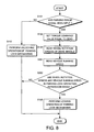
- FIG. 8 is a flowchart describing a parking lock operation routine performed by a controller according to the third embodiment of this invention.
- FIG. 9 is a diagram showing characteristics of a parking lock operation permission range map stored by the controller according to the third embodiment of this invention.
- FIG. 10 is a flowchart describing a parking lock operation routine performed by a controller according to a fourth embodiment of this invention.
- FIG. 11 is a diagram showing characteristics of a parking lock operation permission range map stored by a controller according to a fifth embodiment of this invention.
- FIG. 12 is a schematic diagram of an electric-drive vehicle provided with a parking lock device according to a sixth embodiment of this invention.
- FIG. 13 is a flowchart describing a parking lock operation routine performed by a controller according to the sixth embodiment of this invention.
- FIG. 14 is a flowchart describing a parking lock operation routine performed by a controller according to a seventh embodiment of this invention.
- a rear drive type electric-drive vehicle which runs using electric power supplied from a battery BAT comprises a right front wheel 3 FR, a left front wheel 3 FL, a right rear wheel 3 RR, and a left rear wheel 3 RL.
- This invention may however be applied to a front drive vehicle or a four-wheel drive vehicle rather than a rear drive vehicle.
- the right rear wheel 3 RR is connected to an electric motor 1 R via a gear 2 R.
- the left rear wheel 3 RL is connected to an electric motor 1 L via a gear 2 L.
- the electric motor 1 R ( 1 L) rotates in accordance with an electric power supplied from the battery BAT via an inverter 4 and drives the right rear wheel 3 RR (left rear wheel 3 RL) to rotate via the gear 2 R ( 2 L).
- a brake rotor is fixed to each of the wheels 3 FR, 3 FL, 3 RR, 3 RL.
- a friction brake 8 applies a braking force to the brake rotor of each of the wheels 3 FR, 3 FL, 3 RR, 3 RL.
- Each of the right rear wheel 3 RR and the left rear wheel 3 RL is provided with a parking lock mechanism 6 .
- the parking lock mechanism 6 functions to prevent the wheel 3 RR ( 3 RL) from rotating against a rotation torque input from the electric motor 1 R ( 1 L) or a rotation torque input from a road surface.
- the parking lock mechanism 6 comprises a ratchet wheel 61 , a parking pawl 62 , a parking rod 63 , and a parking lock actuator 12 .
- the ratchet wheel 61 is fixed onto an outer circumference of a rotation shaft 33 of the electric motor 1 R ( 1 L), thereby rotating together with the electric motor 1 R ( 1 L).
- the ratchet wheel 61 comprises teeth 61 a formed in an outer circumference thereof at equal angular intervals.
- a groove 61 b is formed between adjacent teeth 61 a .
- the parking pawl 62 is a lever-like member, a base end of which is pivoted on a shaft 64 supported by a case 34 of the electric motor 1 R ( 1 L).
- a projection 62 a is formed at a tip of the parking pawl 62 so as to project towards the ratchet wheel 61 .
- the parking pawl 62 by turning around the shaft 64 , causes the projection 62 a to engage with one of the grooves 61 b , thereby preventing the ratchet wheel 61 from rotating in any rotation direction.
- the parking pawl 62 is biased by a torsion spring 65 supported by the case 34 towards a turning direction to release the projection 62 a from engagement with the groove 61 b , or in other words in an unlocking direction.
- the parking rod 63 is driven by the parking lock actuator 12 to displace in right and left directions in the figure.
- the parking rod 63 comprises a tip portion 63 a and a base portion 63 b.
- the tip portion 63 a is wedged between a support 11 fixed to the case 34 and the parking pawl 62 biased by the torsion spring 65 in the unlocking direction.
- the base portion 63 b is connected to the parking lock actuator 12 via a link mechanism.
- the parking lock actuator 12 is constituted by an electric-drive or hydraulic type rotary actuator, for example.
- the link mechanism converts a rotation of the parking lock actuator 12 into a linear motion of the parking rod 63 .
- the tip portion 63 a is formed to have a larger diameter than the base portion 63 b and a step 63 e is formed at a boundary there-between.
- a pusher 63 c is fitted onto an outer circumference of the base portion 63 b so as to be free to slide along the base portion 63 b .
- the pusher 63 c comprises a tapered face 63 f which gradually decreases in diameter towards a tip.
- a coil spring 63 d is fitted onto the outer circumference of the base portion 63 b to bias the pusher 63 c towards the tip portion 63 b .
- An end of the coil spring 63 d is in contact with the pusher 63 c on the opposite side thereof to the tapered face 63 f and another end of the coil spring 63 d is supported by a spring seat 63 g which is fixed to the outer circumference of the base portion 63 b .
- the step 63 e functions as a stopper to stop the pusher 63 c moving towards the tip portion 63 a .
- An inclined surface is formed on each of the parking pawl 62 and the support 11 so as to face the tapered face 63 f.
- the pusher 63 c is detached from the parking pawl 62 and the support 11 and the parking pawl 62 biased by the torsion spring 65 in the unlocking direction grips the tip portion 63 a of the parking rod 63 .
- the projection 62 a of the parking pawl 62 is not engaged with the groove 61 b of the ratchet wheel 61 , and the ratchet wheel 61 is allowed to rotate arbitrarily.
- This state corresponds to an unlock state of the parking lock mechanism 6 .
- the pusher 63 c is wedged between the inclined surfaces of the parking pawl 62 and the support 11 so as to turn the parking pawl 62 against the torsion spring 65 in a clockwise direction in the figure.
- the projection 62 a of the parking pawl 62 engages with one of the grooves 61 b of the ratchet wheel 61 .
- the rotation shaft 33 is firmly locked and cannot rotate even when a rotation torque of the electric motor 1 R ( 1 L) or a rotation torque input from a road surface into the wheel 3 RR ( 3 RL) is exerted on the rotation shaft 33 .
- This state corresponds to a lock state of the parking lock mechanism 6 .
- the reason why the pusher 63 c is not fixed to the parking rod 63 but supported by the coil spring 63 d is to limit a turning force which is exerted on the parking pawl 62 by the pusher 63 c .
- a wheel rotation speed of the wheel 3 RR ( 3 RL) is higher than a predetermined parking lock prevention wheel rotation speed
- the projection 62 a of the parking pawl 62 is bounced by the teeth 61 a of the rotating ratchet wheel 61 and prevented from engaging with one of the grooves 61 b .
- the pusher 63 c is thereby pushed back in the unlock direction against the biasing force of the coil spring 63 d.
- the parking lock mechanism 6 is prevented from being activated at a wheel rotation speed exceeding the predetermined parking lock prevention wheel rotation speed irrespective of the driving force of the parking lock actuator 12 .
- Preventing the parking lock mechanism 6 from being activated at a wheel rotation speed exceeding the predetermined parking lock prevention wheel rotation speed is preferable in terms of ensuring stability of vehicle behavior and protecting the parking lock mechanism 6 .
- the predetermined parking lock prevention wheel rotation speed can be set arbitrarily by modifying a spring load of the coil spring 63 d .
- the predetermined parking lock prevention wheel rotation speed is set at ten kilometers per hour (10 km/hr).
- the operation of the parking lock actuator 12 is controlled by a parking lock operation control part 10 in a vehicle controller CU.
- the parking lock operation control part 10 is a virtual unit for the purpose of describing a special function of the vehicle controller CU, and does not exist as a physical entity.
- the vehicle controller CU controls a driving force, a braking force, and steering of the vehicle.
- detection signals are input into the vehicle controller CU from a wheel rotation speed sensor 5 R that detects a wheel rotation speed of the right rear wheel 3 RR, a wheel rotation speed sensor 5 L that detects a wheel rotation speed of the left rear wheel 3 RL, a steering angle sensor S 1 that detects a steering angle of the vehicle, an accelerator pedal depression sensor S 2 that detects a depression amount of an accelerator pedal depressed by a driver of the vehicle, a brake pedal depression sensor S 3 that detects a depression amount of a brake pedal depressed by the driver, a mode selection switch S 4 that detects a running mode or a shift lever position designated by the driver, a yaw rate sensor S 5 that detects a yaw rate of the vehicle, a lateral acceleration sensor S 6 that detects a lateral acceleration of the vehicle, and a front-aft acceleration sensor S 7 that detects a front-aft acceleration of the vehicle
- the vehicle controller CU calculates, on the basis of the input signals, torque command values for the electric motors 1 R and 1 L, and inputs the calculated torque command values into a motor controller MCU.
- the motor controller MCU outputs command signals corresponding to the torque command values to the inverters 4 connected to the electric motors 1 R and 1 L, respectively.
- the inverter 4 supplies electric power corresponding to the command signal from the battery BAT to the electric motor 1 R ( 1 L).
- the vehicle controller CU is constituted by a microcomputer comprising a central processing unit (CPU), a read-only memory (ROM), a random access memory (RAM), and an input/output interface (I/O interface).
- the controller may be constituted by a plurality of microcomputers.
- the motor controller MCU is constituted by a similar microcomputer. It is possible to constitute one or both of the vehicle controller CU and the motor controller MCU by plural microcomputers. It is also possible to constitute the vehicle controller CU and the motor controller MCU by one sole microcomputer.
- the parking lock operation control part 10 serving as a function of the vehicle controller CU controls operations of the parking lock actuator 12 .
- the parking lock operation control part 10 performs this routine at regular time intervals, ten milliseconds, for example, while the vehicle is running.
- the parking lock operation control part 10 determines if a parking range signal has been input from the mode selection switch S 4 .
- the parking range signal is a signal generated by the mode selection switch S 4 and input into the parking lock operation control part 10 every time the shift lever shifts to the parking range.
- the parking lock operation control part 10 When the determination in the step S 101 is negative, or in other words when the shift lever has not shifted to the parking range, the parking lock operation control part 10 performs an unlocking operation of the parking lock mechanism 6 in a step S 110 . Specifically, the parking lock operation control part 10 outputs a signal to the parking lock actuator 12 to make the parking pawl 62 turn to or stay in the unlock state shown in FIG. 2 . After the processing, the parking lock operation control part 10 terminates the routine.
- the parking lock operation control part 10 performs a locking operation of the parking lock mechanism 6 in steps S 102 -S 105 .
- the parking lock operation control part 10 sets the torque command values for the electric motors 1 R and 1 L equal to zero.
- the motor controller MCU outputs command signals corresponding to the torque command values equal to zero to the inverters 4 so as to cut off the electric power supply from the battery BAT to the electric motors 1 R and 114 , respectively.
- the reason why the electric power supply to the electric motors 1 R and 1 L is cut off is that the operation of the electric motors 1 R and 1 L is not necessary when the parking lock mechanisms 6 are activated.
- the parking lock operation control part 10 reads the wheel rotation speed of the right rear wheel 3 RR detected by the wheel rotation speed sensor 5 R and the wheel rotation speed of the left rear wheel 3 RL detected by the wheel rotation speed sensor 5 L.
- the parking lock operation control part 10 refers to a map stored previously in the ROM of the vehicle controller CU. The characteristics of the map are shown in FIG. 5 .
- the parking lock operation control part 10 determines if a point corresponding to the wheel rotation speed of the right rear wheel 3 RR and the wheel rotation speed of the left rear wheel 3 RL resides in a hatched zone in the figure.
- the hatched zone is set on both sides of a center line at which the rotation speed of the right rear wheel 3 RR and the rotation speed of the left rear wheel 3 RL are equal.
- the hatched zone has a band width of 0.5 km/hr on both sides of the center line.
- the hatched zone is limited by the predetermined parking lock prevention wheel rotation speed of 10 km/hr that is determined based on the spring load of the coil spring 63 d , thereby limiting the rotation speed of the right rear wheel 3 RR and the rotation speed of the left rear wheel 3 RL not to exceed the predetermined parking lock prevention wheel rotation speed of 10 km/hr.
- This zone is referred to as a parking lock operation permission range.
- the determination of the step S 104 is affirmative. In other cases, the determination of the step S 104 is negative.
- the parking lock operation control part 10 When the determination in the step S 104 is affirmative, the parking lock operation control part 10 performs processing of the step S 105 . When the determination in the step S 104 is negative, the parking lock operation control part 10 immediately terminates the routine without performing a locking operation of the parking lock mechanisms 6 .
- the parking lock operation control part 10 performs a locking operation of the parking lock mechanisms 6 . Specifically, by outputting signals to the parking lock actuators 12 , the parking lock operation control part 10 operates the parking lock mechanisms 6 to the lock state as shown in FIG. 3 . After performing the processing of the step S 105 , the parking lock operation control part 10 terminates the routine.
- the locking operation of the parking lock mechanism 6 is performed upon detecting a shift of the shift lever to the parking range and the unlock operation of the parking lock mechanism 6 is performed upon detecting a shift of the shift lever to another range.
- This parking lock operation routine defines a permitting condition of the locking operation of the parking lock mechanism 6 as follows.
- Both of the rotation speeds of the right rear wheel 3 RR and the left rear wheel 3 RL are within the predetermined parking lock prevention wheel rotation speed of 10 km/hr, and
- a difference between the rotation speed of the right rear wheel 3 RR and the rotation speed of the left rear wheel 3 RL is within a predetermined difference of 0.5 km/hr.
- the rotation speed of the right rear wheel 3 RR does not necessarily coincide with the rotation speed of the left rear wheel 3 RL due to a difference in friction factors of the road surface. It is therefore possible that the rotation speed of the right rear wheel 3 RR exceeds the predetermined parking lock prevention wheel rotation speed of 10 km/hr, which is determined on the basis of the aforesaid spring load of the coil spring 63 d , while the rotation speed of the left rear wheel 3 RL stays within the predetermined parking lock prevention wheel rotation speed of 10 km/hr. If the shift lever is operated to the parking range in this state, rotation of the left rear wheel 3 RL is locked while rotation of the right rear wheel 3 RR is not locked according to the prior art parking lock device.
- Locking rotation of only one of the pair of the drive wheels may result in unstable vehicle behavior and adversely affect the durability of the parking lock mechanisms 6 .
- the parking lock operation routine performed by the parking lock operation control part 10 according to this invention does not permit the parking lock mechanism 6 to perform a locking operation when the condition (1) is not satisfied.
- the projection 62 a of the parking pawl 62 is bounced by the tooth 61 a of the ratchet wheel 61 in the right rear wheel 3 RR so that the projection 62 a is not able to engage with one of the grooves 61 b of the ratchet wheel 61 .
- the pusher 63 c is therefore pushed back against the biasing force of the coil spring 63 d and the rotation of the rotation shaft 33 is not locked.
- the projection 62 a of the parking pawl 62 engages with one of the grooves 61 b of the ratchet wheel 61 , thereby locking the rotation of the rotation shaft 33 .
- the locking operation of the parking lock mechanism 6 is not permitted when the condition (2) is not satisfied.
- the locking operation of the parking lock mechanism 6 is not performed unless the rotation of the two drive wheels 3 RR, 3 RL is substantially synchronous. The locking conditions of the right and left drive wheels are thereby kept equal.
- this parking lock operation routine ensures stable vehicle behavior in a specific parking lock condition that cannot be ensured by a mechanical inactivating mechanism.
- the parking lock mechanisms 6 , the wheel rotation speed sensors 5 R, 5 L, and the parking lock operation control part 10 constitute the parking lock device.
- a parking lock operation permission range map is stored in advance in the ROM of the vehicle controller CU instead of the parking lock operation permission range map of FIG. 6 referred to in the first embodiment.
- the parking lock operation permission range map referred to in the first embodiment sets the parking lock operation permission range such that a difference between the rotation speeds of the right rear wheel 3 RR and the left rear wheel 3 RL is within the predetermined deviation of 0.5 km/hr, as shown in FIG. 5 .
- the parking lock operation permission range is enlarged as the wheel rotation speeds decrease.
- the rotation speed of one of the drive wheels 3 RR, 3 RL is equal to the predetermined parking lock prevention wheel rotation speed of 10 km/hr
- the rotation speed of the other drive wheel 3 RL ( 3 RR) is limited within a range of 9.5-10 km/hr.
- the difference in the rotation speeds of the drive wheels 3 RL, 3 RR is substantially limited to the predetermined difference of 0.5 km/hr. This value is common to the parking lock operation permission range map shown in FIG. 5 .
- the rotation speed of one of the drive wheels 3 RR ( 3 RL) when the rotation speed of one of the drive wheels 3 RR ( 3 RL) is zero, the rotation speed of the other drive wheel 3 RL ( 3 RR) may fluctuate within a range of 0-2 km/hr. In other words, when the wheel rotation speed is in the vicinity of zero, the difference in the rotation speeds of the drive wheels 3 RL and 3 RR is allowed to be as large as 2 km/hr.
- FIGS. 7-9 a third embodiment of this invention will be described.
- the parking lock operation routine according to the first embodiment determines the permitting condition of the locking operation of the parking lock mechanism 6 in accordance with the rotation speeds of the right rear wheel 3 RR and the left rear wheel 3 RL, and the difference there-between.
- the parking lock operation routine according to this embodiment determines the permitting condition in view of a vehicle running speed also.
- the parking lock device further comprises a vehicle speed sensor 5 a .
- the vehicle running speed detected by the vehicle speed sensor 5 a is input into the vehicle controller CU as a signal.
- the vehicle speed sensor 5 a may be materialized in various fashions. For example, it is possible to provide the four wheels 3 FR, 3 FL, 3 RR, 3 RL with the wheel rotation speed sensor such that an average of the detected wheel rotation speeds is taken as the vehicle running speed. Alternatively, an average value of the wheel rotation speeds of the front wheels 3 FR and 3 FL, which are driven wheels, may be taken as the vehicle running speed. Further, the higher of the wheel rotation speeds of the front wheels 3 FR and 3 FL may be taken as the vehicle running speed.
- the vehicle running speed may be calculated by integrating the signals output from the front-aft acceleration sensor S 7 . Still further, the vehicle running speed may be calculated from output signals from a GPS sensor using the Global Positioning System.
- steps S 201 and S 202 are provided instead of the step S 104 .
- the other steps of the routine are common to the parking lock operation routine according to the first embodiment.
- step S 201 the parking lock operation control part 10 reads the vehicle running speed.
- the parking lock operation control part 10 refers to a map, the characteristics of which are shown in FIG. 9 , to determine if the rotation speed of the right rear wheel 3 RR, the rotation speed of the left rear wheel 3 RL, and the vehicle running speed are in the parking lock operation permission range corresponding to a hatched zone in FIG. 9 .
- This map is stored previously in the ROM of the vehicle controller CU.
- an abscissa represents a vehicle running speed and an ordinate represents the rotation speeds of the right rear wheel 3 RR and the left rear wheel 3 RL.
- This diagram defines the locking operation permitting condition of the parking lock mechanism 6 as follows.
- Both of the rotation speeds of the right rear wheel 3 RR and the left rear wheel 3 RL are within the predetermined parking lock prevention wheel rotation speed of 10 km/hr, and
- condition (1) is equivalent to the condition (1) defined in the first embodiment.
- the effect brought about by the condition (1) in the first embodiment is also obtained in this embodiment.
- condition (2A) brings about a similar effect as the condition (2), but since the deviation between the wheel rotation speeds of the rear wheels 3 RR, 3 RL and the vehicle running speed is taken as a factor in determining the lock condition, coincidence of the vehicle behavior and the behavior of the rear wheels when the parking lock is activated can be further ensured.
- the hardware composition of this embodiment is identical to that of the third embodiment. According to this embodiment, however, the parking lock operation control part 10 performs a different parking lock operation routine from that of the third embodiment.
- the permitting condition of the locking operation of the parking lock mechanism 6 is determined on the basis of a map having the characteristics shown in FIG. 9 .
- the parking lock operation routine according to this embodiment mitigates the permitting condition of the locking operation of the parking lock mechanism 6 depending on the vehicle running speed.
- a step S 301 is provided between the step S 202 and the step S 110 of the parking lock operation routine according to the third embodiment.
- the processing of the other steps is identical to that of the parking lock operation routine according to the third embodiment.
- the parking lock operation control part 10 determines if the vehicle running speed is within 1 km/hr. If the determination is affirmative, the parking lock operation control part 10 performs the locking operation of the parking lock mechanisms 6 in the step S 105 . If the determination is negative, the parking lock operation control part 10 performs the unlocking operation of the parking lock mechanism 6 in the step S 110 and terminates the routine.
- condition (1) of the third embodiment is applied without modification but the condition (2A) is slightly modified to determine the permitting conditions of the locking operation of the parking lock mechanism 6 .
- the condition (1) of the third embodiment is applied without modification but the condition (2A) is slightly modified to determine the permitting conditions of the locking operation of the parking lock mechanism 6 .
- the locking operation of the parking lock mechanisms 6 of the right rear wheel 3 RR and the left rear wheel 3 RL is permitted as long as the vehicle running speed is within 1 km/hr.
- the vehicle running speed is higher than 1 km/hr, on other hand, the locking operation of the parking lock mechanisms 6 of the right rear wheel 3 RR and the left rear wheel 3 RL is prohibited.
- the hardware composition of this embodiment is identical to that of the first embodiment.
- the parking lock operation routine performed by the parking lock operation control part 10 is basically identical to that of the first embodiment. In this embodiment, however, the contents of the map referred to in the step S 104 are different from those of the map used in the third embodiment.
- a map having the characteristics shown in FIG. 11 is used instead of the map having the content shown in FIG. 5 .
- condition (2) of the first embodiment is mitigated in a low wheel speed range of the right rear wheel 3 RR and the left rear wheel 3 RL.
- a parking lock operation in a low vehicle speed range can be accomplished in a short time, as in the case of the second and the fourth embodiment.
- FIG. 12 and FIG. 13 a sixth embodiment of this invention will be described.
- the vehicle is a so-called two-wheel drive vehicle having the right rear wheel 3 RR and the left rear wheel 3 RL as drive wheels and the right front wheel 3 FR and the left front wheel 3 FL as driven wheels.
- the parking lock mechanism 6 is provided for the drive wheels, i.e., the right rear wheel 3 RR and the left rear wheel 3 RL, only.
- the vehicle to which this embodiment is applied is a so-called four-wheel-drive vehicle having four wheels 3 FR, 3 FL, 3 RR, 3 RL that are driven by electric motors 1 FR, 1 FL, 1 RR, 1 RL, respectively.
- the parking lock mechanism 6 is provided for each of the four wheels 3 FR, 3 FL, 3 RR, 3 RL.
- the wheel rotation speed sensors 5 FR, 5 FL, 5 RR, 5 RL are provided for the four wheels 3 FR, 3 FL, 3 RR, 3 RL, respectively.
- the locking operation of the parking lock mechanism 6 is performed in a pair of one of the right front wheel 3 FR and the right rear wheel 3 RR and one of the left front wheel 3 FL and the left rear wheel 3 RL. Specifically, the locking operation of the parking lock mechanism 6 is performed for one of the pairs shown in the following tables.
- the parking lock operation control part 10 performs a parking lock operation routine shown in FIG. 13 instead of the parking lock operation routine according to the third embodiment shown in FIG. 8 .
- the difference between this parking lock operation routine and the parking lock operation routine shown in FIG. 8 is that the determination of the difference in the wheel rotation speeds is performed not for the rear two wheels 3 RR, 3 RL, but for the four wheels 3 FR, 3 FL, 3 RR, 3 RL.
- steps S 401 , S 402 , and S 403 are provided in the parking lock operation routine according to this embodiment instead of the steps S 103 , S 202 , and S 105 of FIG. 8 .
- the parking lock operation control part 10 reads wheel speeds of the four wheels 3 FR, 3 FL, 3 RR, 3 RL.
- the parking lock operation control part 10 determines a permitting condition of the locking operation of the parking lock mechanisms 6 on the basis of the wheel speeds of the four wheels 3 FR, 3 FL, 3 RR, 3 RL and the vehicle running speed read in the step S 201 by referring to the map having the characteristics shown in FIG. 9 .
- the determination is performed for the pair of the right front wheel 3 FR and the left front wheel 3 FL shown in TABLE-1, the pair of the right rear wheel 3 RR and the left rear wheel 3 RL shown in TABLE-2, the pair of the right front wheel 3 FR and the left rear wheel 3 RL shown in TABLE-3, and the pair of the right rear wheel 3 RR and the left front wheel 3 FL shown in TABLE-4, respectively.
- the parking lock operation control part 10 determines if there is a pair that satisfies the permitting condition defined in the map of FIG. 9 .
- step S 402 if a pair of wheels that satisfies the condition defined in the map of FIG. 9 exists, the parking lock operation control part 10 performs the locking operation of the parking lock mechanisms 6 on the relevant pair in a step S 403 . It should be noted that when plural pairs that satisfy the condition defined in the map of FIG. 9 exist, a pair of wheels is selected from the plural pairs according to a predetermined priority.
- step S 302 when no pair of wheels satisfies the condition defined in the map of FIG. 9 , the parking lock operation control part 10 terminates the routine without performing the locking operation of the parking lock mechanisms 6 .
- any of the above pairs is constituted by right and left wheels, there is no possibility that the locking operation will be performed only for the right wheels or the left wheels.
- the number of pairs of wheels on which the locking operation of the parking lock mechanisms 6 is determined is increased and the parking lock operation can be accomplished in a short time without inducing unstable vehicle behavior.
- a step S 501 is provided instead of the step S 202 of the routine in FIG. 8 according to the third embodiment.
- the parking lock operation control part 10 determines if the wheel rotation speed of the right rear wheel 3 RR and the wheel rotation speed of the left rear wheel 3 RL are in the hatched zone in FIG. 9 .
- the parking lock operation control part 10 further determines if a difference between the wheel rotation speed of the right rear wheel 3 RR and the wheel rotation speed of the left rear wheel 3 RL is within a predetermined difference.
- the parking lock operation control part 10 performs the locking operation of the parking lock mechanisms 6 in the step S 105 only when both of these two conditions are satisfied. When at least one of the two conditions is not satisfied, the parking lock operation control part 10 terminates the routine without performing the locking operation of the parking lock mechanisms 6 .
- the permitting condition of the locking operation of the parking lock mechanisms 6 is determined on the basis of the difference between the wheel rotation speeds in addition to the deviation between the wheel speeds and the vehicle running speed, the vehicle behavior in response to the locking operation of the parking lock mechanisms 6 becomes more stable than in the case of the first-sixth embodiments.
- the first to fifth embodiments and the seventh embodiment described above are directed to a rear drive vehicle in which each of the right rear wheel and the left rear wheel is provided with an electric motor and a parking lock mechanism.
- these embodiments can be applied to a front drive vehicle in which each of the right front wheel and the left front wheel is provided with an electric motor and a parking lock mechanism, or a four-wheel-drive vehicle in which each of the four wheels is provided with an electric motor and a parking lock mechanism.
- this invention can be applied to any type of vehicle such as a hybrid-drive electric vehicle or a vehicle driven by an internal combustion engine as long as the vehicle has right and left wheels each of which is provided with a parking lock mechanism.
- this invention is suited for control of a parking lock device of an electric-drive vehicle but not limited thereto.
Landscapes
- Engineering & Computer Science (AREA)
- General Engineering & Computer Science (AREA)
- Mechanical Engineering (AREA)
- Transportation (AREA)
- Regulating Braking Force (AREA)
- Electric Propulsion And Braking For Vehicles (AREA)
Applications Claiming Priority (3)
| Application Number | Priority Date | Filing Date | Title |
|---|---|---|---|
| JP2009054962 | 2009-03-09 | ||
| JP2009-054962 | 2009-03-09 | ||
| PCT/JP2010/054271 WO2010104189A1 (fr) | 2009-03-09 | 2010-03-08 | Dispositif de verrouillage de stationnement |
Publications (2)
| Publication Number | Publication Date |
|---|---|
| US20120041661A1 US20120041661A1 (en) | 2012-02-16 |
| US9045115B2 true US9045115B2 (en) | 2015-06-02 |
Family
ID=42728472
Family Applications (1)
| Application Number | Title | Priority Date | Filing Date |
|---|---|---|---|
| US13/202,191 Expired - Fee Related US9045115B2 (en) | 2009-03-09 | 2010-03-08 | Parking lock device |
Country Status (5)
| Country | Link |
|---|---|
| US (1) | US9045115B2 (fr) |
| EP (1) | EP2406111B1 (fr) |
| JP (1) | JP5141827B2 (fr) |
| CN (1) | CN102348583B (fr) |
| WO (1) | WO2010104189A1 (fr) |
Cited By (2)
| Publication number | Priority date | Publication date | Assignee | Title |
|---|---|---|---|---|
| US20250135875A1 (en) * | 2023-10-30 | 2025-05-01 | Kubota Corporation | Electric work vehicle |
| EP4570548A1 (fr) * | 2023-10-30 | 2025-06-18 | Kubota Corporation | Véhicule de travail électrique |
Families Citing this family (24)
| Publication number | Priority date | Publication date | Assignee | Title |
|---|---|---|---|---|
| JP5703979B2 (ja) * | 2011-06-07 | 2015-04-22 | 日産自動車株式会社 | 車両のパーキングロック制御装置 |
| JP2013075651A (ja) | 2011-06-07 | 2013-04-25 | Nissan Motor Co Ltd | 車両のパーキングロック制御装置 |
| DE102011080236A1 (de) * | 2011-08-02 | 2013-02-07 | Zf Friedrichshafen Ag | Antriebsvorrichtung für ein einzelnes Rad eines Kraftfahrzeugs |
| JP5834993B2 (ja) * | 2012-02-20 | 2015-12-24 | 日産自動車株式会社 | 車両のパークロック装置 |
| JP6195432B2 (ja) * | 2012-10-03 | 2017-09-13 | Ntn株式会社 | インホイールモータ駆動装置 |
| DE102013000032A1 (de) * | 2013-01-04 | 2014-07-10 | Getrag Getriebe- Und Zahnradfabrik Hermann Hagenmeyer Gmbh & Cie Kg | Verfahren zum Einlegen einer Parksperre eines Kraftfahrzeugantriebsstranges |
| JP6299956B2 (ja) * | 2013-12-25 | 2018-03-28 | 三菱自動車工業株式会社 | 電動車両用駆動装置 |
| JP5975051B2 (ja) * | 2014-02-26 | 2016-08-23 | トヨタ自動車株式会社 | 車両制御装置及び車両制御方法 |
| JP6065890B2 (ja) * | 2014-10-17 | 2017-01-25 | トヨタ自動車株式会社 | 車両の停車中における衝撃検出システムおよび衝撃検出方法 |
| TWI579178B (zh) * | 2015-05-20 | 2017-04-21 | zheng-yi Huang | Automatic brake device for hand pushing |
| GB2548102B (en) * | 2016-03-07 | 2018-07-25 | Jaguar Land Rover Ltd | Braking control system |
| JP6737083B2 (ja) * | 2016-09-05 | 2020-08-05 | トヨタ自動車株式会社 | 電気自動車 |
| JP6617726B2 (ja) * | 2017-02-01 | 2019-12-11 | トヨタ自動車株式会社 | 運転制御装置 |
| JP6442540B2 (ja) * | 2017-02-21 | 2018-12-19 | 本田技研工業株式会社 | 駆動装置 |
| CN107642605A (zh) * | 2017-08-18 | 2018-01-30 | 潍柴动力股份有限公司 | 用于汽车防溜车的控制装置及控制方法 |
| CN107605607B (zh) * | 2017-09-15 | 2019-08-02 | 北理慧动(常熟)车辆科技有限公司 | 发动机控制方法及装置 |
| DE102018206824A1 (de) | 2018-05-03 | 2019-11-07 | Robert Bosch Gmbh | Steuervorrichtung und Verfahren zum Betreiben einer Parkbremsvorrichtung eines Fahrzeugs |
| DE102019200600B3 (de) | 2018-10-15 | 2020-06-18 | Vitesco Technologies Germany Gmbh | Verfahren zur Prädiktion einer Störung an einem Aktuator in einem Fahrzeug und applikationsspezifischer Schaltkreis zur Umsetzung eines solchen Verfahrens |
| WO2022049088A1 (fr) | 2020-09-04 | 2022-03-10 | Hofer Powertrain Innovation Gmbh | Entraînement de véhicule automobile à moteur électrique de type à bloc pour entraînements à roue unique, en particulier comprenant deux verrous de stationnement |
| DE202021104326U1 (de) | 2020-09-04 | 2021-12-10 | Hofer Powertrain Innovation Gmbh | Elektromotorischer Kfz-Antrieb mit zwei Parksperren |
| JP7535004B2 (ja) * | 2021-03-30 | 2024-08-15 | 本田技研工業株式会社 | 車両制御システム、車両、車両制御方法 |
| US12227157B2 (en) * | 2021-10-01 | 2025-02-18 | Ford Global Technologies, Llc | Methods and apparatus to extend brake life cycle |
| US20230394895A1 (en) * | 2022-06-02 | 2023-12-07 | Electric Propulsion Technologies, LLC | System and method for diagnosing a park function for an in-wheel electric motor |
| CN115891673B (zh) * | 2022-09-29 | 2024-10-11 | 郑州日产汽车有限公司 | 一种电机驻车机构及驻车方法 |
Citations (16)
| Publication number | Priority date | Publication date | Assignee | Title |
|---|---|---|---|---|
| DE19943519A1 (de) | 1999-09-11 | 2001-03-29 | Zahnradfabrik Friedrichshafen | Verfahren zur Steuerung eines Parksperrensystems für ein Automatgetriebe |
| US6367589B1 (en) * | 1999-11-01 | 2002-04-09 | New Holland North America, Inc. | Parking lock for agricultural implement |
| US20020189383A1 (en) * | 1999-10-21 | 2002-12-19 | Axel Schamscha | Double clutch transmission and method for controlling an automated double clutch transmission |
| US20030125859A1 (en) * | 2001-12-28 | 2003-07-03 | Dix Peter J. | Skid steer vehicle having anti-rolling system |
| US20040060753A1 (en) * | 1999-10-08 | 2004-04-01 | Toyota Jidosha Kabushiki Kaisha | Hybrid drive system wherein clutch is engaged when engine speed has exceeded motor speed upon switching from motor drive mode to engine drive mode |
| US20050082096A1 (en) * | 2003-10-15 | 2005-04-21 | Aisin Aw Co., Ltd. | Electrically powered vehicle drive control device and electrically powered vehicle drive control method |
| JP2005348467A (ja) | 2004-05-31 | 2005-12-15 | Toyota Motor Corp | 車両 |
| JP2006044458A (ja) | 2004-08-04 | 2006-02-16 | Toyota Motor Corp | パーキングロック装置 |
| WO2006025217A1 (fr) | 2004-09-01 | 2006-03-09 | Toyota Jidosha Kabushiki Kaisha | Vehicule a moteur et sa methode de regulation |
| US20060173584A1 (en) * | 2003-06-30 | 2006-08-03 | Frank Einig | Method and apparatus for detecting and correcting trailer induced yaw movements in a towing vehicle |
| US20060196712A1 (en) * | 2005-03-04 | 2006-09-07 | Nissan Motor Co., Ltd. | Vehicle regenerative braking control apparatus and method |
| US20080127772A1 (en) * | 2004-12-02 | 2008-06-05 | Zf Friedrichshafen Ag | Parking Lock For a Motor Vehicle |
| DE102007001495A1 (de) | 2007-01-10 | 2008-07-17 | Zf Friedrichshafen Ag | Verfahren zur Steuerung eines Parksperrensystems eines Automatgetriebes eines Fahrzeugs |
| US20080262687A1 (en) * | 2007-04-20 | 2008-10-23 | Toyota Jidosha Kabushiki Kaisha | Electric parking brake system and method for controlling the same |
| JP2008290562A (ja) | 2007-05-24 | 2008-12-04 | Toyota Motor Corp | 車両用制御装置 |
| US20090326767A1 (en) * | 2006-09-01 | 2009-12-31 | Toyota Jidosha Kabushiki Kaisha | Vehicle control apparatus, vehicle control method, computer program for implementing same method, and data storage medium storing same computer program |
-
2010
- 2010-03-08 WO PCT/JP2010/054271 patent/WO2010104189A1/fr not_active Ceased
- 2010-03-08 CN CN201080011651.0A patent/CN102348583B/zh not_active Expired - Fee Related
- 2010-03-08 EP EP10750938.2A patent/EP2406111B1/fr not_active Not-in-force
- 2010-03-08 US US13/202,191 patent/US9045115B2/en not_active Expired - Fee Related
- 2010-03-08 JP JP2011536659A patent/JP5141827B2/ja not_active Expired - Fee Related
Patent Citations (19)
| Publication number | Priority date | Publication date | Assignee | Title |
|---|---|---|---|---|
| DE19943519A1 (de) | 1999-09-11 | 2001-03-29 | Zahnradfabrik Friedrichshafen | Verfahren zur Steuerung eines Parksperrensystems für ein Automatgetriebe |
| US20040060753A1 (en) * | 1999-10-08 | 2004-04-01 | Toyota Jidosha Kabushiki Kaisha | Hybrid drive system wherein clutch is engaged when engine speed has exceeded motor speed upon switching from motor drive mode to engine drive mode |
| US20020189383A1 (en) * | 1999-10-21 | 2002-12-19 | Axel Schamscha | Double clutch transmission and method for controlling an automated double clutch transmission |
| US6367589B1 (en) * | 1999-11-01 | 2002-04-09 | New Holland North America, Inc. | Parking lock for agricultural implement |
| US20030125859A1 (en) * | 2001-12-28 | 2003-07-03 | Dix Peter J. | Skid steer vehicle having anti-rolling system |
| US20060173584A1 (en) * | 2003-06-30 | 2006-08-03 | Frank Einig | Method and apparatus for detecting and correcting trailer induced yaw movements in a towing vehicle |
| US20050082096A1 (en) * | 2003-10-15 | 2005-04-21 | Aisin Aw Co., Ltd. | Electrically powered vehicle drive control device and electrically powered vehicle drive control method |
| JP2005348467A (ja) | 2004-05-31 | 2005-12-15 | Toyota Motor Corp | 車両 |
| JP2006044458A (ja) | 2004-08-04 | 2006-02-16 | Toyota Motor Corp | パーキングロック装置 |
| WO2006025217A1 (fr) | 2004-09-01 | 2006-03-09 | Toyota Jidosha Kabushiki Kaisha | Vehicule a moteur et sa methode de regulation |
| CN1976835A (zh) | 2004-09-01 | 2007-06-06 | 丰田自动车株式会社 | 机动车辆及其控制方法 |
| US20080033617A1 (en) * | 2004-09-01 | 2008-02-07 | Hideto Watanabe | Motor Vehicle And Control Method Of The Same |
| US20080127772A1 (en) * | 2004-12-02 | 2008-06-05 | Zf Friedrichshafen Ag | Parking Lock For a Motor Vehicle |
| US20060196712A1 (en) * | 2005-03-04 | 2006-09-07 | Nissan Motor Co., Ltd. | Vehicle regenerative braking control apparatus and method |
| US20090326767A1 (en) * | 2006-09-01 | 2009-12-31 | Toyota Jidosha Kabushiki Kaisha | Vehicle control apparatus, vehicle control method, computer program for implementing same method, and data storage medium storing same computer program |
| DE102007001495A1 (de) | 2007-01-10 | 2008-07-17 | Zf Friedrichshafen Ag | Verfahren zur Steuerung eines Parksperrensystems eines Automatgetriebes eines Fahrzeugs |
| US20080262687A1 (en) * | 2007-04-20 | 2008-10-23 | Toyota Jidosha Kabushiki Kaisha | Electric parking brake system and method for controlling the same |
| JP2008290562A (ja) | 2007-05-24 | 2008-12-04 | Toyota Motor Corp | 車両用制御装置 |
| US20090176619A1 (en) * | 2007-05-24 | 2009-07-09 | Toyota Jidosha Kabushiki Kaisha | Vehicle control apparatus |
Cited By (3)
| Publication number | Priority date | Publication date | Assignee | Title |
|---|---|---|---|---|
| US20250135875A1 (en) * | 2023-10-30 | 2025-05-01 | Kubota Corporation | Electric work vehicle |
| EP4570548A1 (fr) * | 2023-10-30 | 2025-06-18 | Kubota Corporation | Véhicule de travail électrique |
| US12594828B2 (en) * | 2023-10-30 | 2026-04-07 | Kubota Corporation | Electric work vehicle |
Also Published As
| Publication number | Publication date |
|---|---|
| US20120041661A1 (en) | 2012-02-16 |
| CN102348583B (zh) | 2014-07-09 |
| EP2406111A4 (fr) | 2013-06-26 |
| EP2406111B1 (fr) | 2014-01-01 |
| JP2012519099A (ja) | 2012-08-23 |
| CN102348583A (zh) | 2012-02-08 |
| JP5141827B2 (ja) | 2013-02-13 |
| WO2010104189A1 (fr) | 2010-09-16 |
| EP2406111A1 (fr) | 2012-01-18 |
Similar Documents
| Publication | Publication Date | Title |
|---|---|---|
| US9045115B2 (en) | Parking lock device | |
| JP4924757B2 (ja) | 車両駆動制御装置 | |
| JP4306770B2 (ja) | 車両およびその制御方法 | |
| JP5945572B2 (ja) | 駆動力制御システムおよび鞍乗り型車両 | |
| KR101576371B1 (ko) | 지능형 isg 제어장치 및 제어방법 | |
| JP6653085B2 (ja) | 車両の駆動力制御装置 | |
| US20160144854A1 (en) | Torque control apparatus | |
| JP2011122607A (ja) | 車両の制御装置 | |
| JP2014156140A (ja) | アクセルペダルの誤操作制御装置 | |
| KR102496487B1 (ko) | Epb 장착 차량의 드리프트 로직 제어 방법 | |
| US9037377B2 (en) | Vehicle | |
| CN103517838A (zh) | 车辆的驻车锁定控制装置及控制方法 | |
| US20140032074A1 (en) | Parking lock control device for vehicle and control method | |
| KR102729873B1 (ko) | 차량용 주행 제어방법 및 시스템 | |
| JP7588950B2 (ja) | 車両制御装置 | |
| JP6388259B2 (ja) | 車両用挙動制御装置 | |
| US20240383336A1 (en) | Vehicle control device, vehicle control method, and vehicle control program | |
| JP5176569B2 (ja) | 車両の制動制御装置 | |
| JP2014069679A (ja) | 車両の制動制御装置 | |
| EP3889004B1 (fr) | Système et procédé de commande auxiliaire pour un véhicule | |
| JP5458925B2 (ja) | 車両の駆動制御装置 | |
| JP2007291909A (ja) | 車両走行制御装置 | |
| JP5810870B2 (ja) | 車両の駆動制御装置 | |
| JP2016124305A (ja) | パークロック制御装置 | |
| JP2006298094A (ja) | 車両停止保持装置 |
Legal Events
| Date | Code | Title | Description |
|---|---|---|---|
| AS | Assignment |
Owner name: NISSAN MOTOR CO., LTD., JAPAN Free format text: ASSIGNMENT OF ASSIGNORS INTEREST;ASSIGNOR:KANEKO, YUTARO;REEL/FRAME:026779/0444 Effective date: 20110606 |
|
| STCF | Information on status: patent grant |
Free format text: PATENTED CASE |
|
| MAFP | Maintenance fee payment |
Free format text: PAYMENT OF MAINTENANCE FEE, 4TH YEAR, LARGE ENTITY (ORIGINAL EVENT CODE: M1551); ENTITY STATUS OF PATENT OWNER: LARGE ENTITY Year of fee payment: 4 |
|
| FEPP | Fee payment procedure |
Free format text: MAINTENANCE FEE REMINDER MAILED (ORIGINAL EVENT CODE: REM.); ENTITY STATUS OF PATENT OWNER: LARGE ENTITY |
|
| LAPS | Lapse for failure to pay maintenance fees |
Free format text: PATENT EXPIRED FOR FAILURE TO PAY MAINTENANCE FEES (ORIGINAL EVENT CODE: EXP.); ENTITY STATUS OF PATENT OWNER: LARGE ENTITY |
|
| STCH | Information on status: patent discontinuation |
Free format text: PATENT EXPIRED DUE TO NONPAYMENT OF MAINTENANCE FEES UNDER 37 CFR 1.362 |
|
| FP | Lapsed due to failure to pay maintenance fee |
Effective date: 20230602 |