US9045182B2 - Plant for assembling mechanical parts on bodies of motor-vehicles - Google Patents
Plant for assembling mechanical parts on bodies of motor-vehicles Download PDFInfo
- Publication number
- US9045182B2 US9045182B2 US12/973,265 US97326510A US9045182B2 US 9045182 B2 US9045182 B2 US 9045182B2 US 97326510 A US97326510 A US 97326510A US 9045182 B2 US9045182 B2 US 9045182B2
- Authority
- US
- United States
- Prior art keywords
- pallets
- pallet
- mechanical parts
- line
- line section
- Prior art date
- Legal status (The legal status is an assumption and is not a legal conclusion. Google has not performed a legal analysis and makes no representation as to the accuracy of the status listed.)
- Active, expires
Links
Images



Classifications
-
- B—PERFORMING OPERATIONS; TRANSPORTING
- B23—MACHINE TOOLS; METAL-WORKING NOT OTHERWISE PROVIDED FOR
- B23P—METAL-WORKING NOT OTHERWISE PROVIDED FOR; COMBINED OPERATIONS; UNIVERSAL MACHINE TOOLS
- B23P19/00—Machines for simply fitting together or separating metal parts or objects, or metal and non-metal parts, whether or not involving some deformation; Tools or devices therefor so far as not provided for in other classes
- B23P19/04—Machines for simply fitting together or separating metal parts or objects, or metal and non-metal parts, whether or not involving some deformation; Tools or devices therefor so far as not provided for in other classes for assembling or disassembling parts
- B23P19/06—Screw or nut setting or loosening machines
-
- B—PERFORMING OPERATIONS; TRANSPORTING
- B62—LAND VEHICLES FOR TRAVELLING OTHERWISE THAN ON RAILS
- B62D—MOTOR VEHICLES; TRAILERS
- B62D65/00—Designing, manufacturing, e.g. assembling, facilitating disassembly, or structurally modifying motor vehicles or trailers, not otherwise provided for
- B62D65/02—Joining sub-units or components to, or positioning sub-units or components with respect to, body shell or other sub-units or components
-
- B—PERFORMING OPERATIONS; TRANSPORTING
- B62—LAND VEHICLES FOR TRAVELLING OTHERWISE THAN ON RAILS
- B62D—MOTOR VEHICLES; TRAILERS
- B62D65/00—Designing, manufacturing, e.g. assembling, facilitating disassembly, or structurally modifying motor vehicles or trailers, not otherwise provided for
- B62D65/02—Joining sub-units or components to, or positioning sub-units or components with respect to, body shell or other sub-units or components
- B62D65/12—Joining sub-units or components to, or positioning sub-units or components with respect to, body shell or other sub-units or components the sub-units or components being suspensions, brakes or wheel units
-
- B—PERFORMING OPERATIONS; TRANSPORTING
- B62—LAND VEHICLES FOR TRAVELLING OTHERWISE THAN ON RAILS
- B62D—MOTOR VEHICLES; TRAILERS
- B62D65/00—Designing, manufacturing, e.g. assembling, facilitating disassembly, or structurally modifying motor vehicles or trailers, not otherwise provided for
- B62D65/02—Joining sub-units or components to, or positioning sub-units or components with respect to, body shell or other sub-units or components
- B62D65/18—Transportation, conveyor or haulage systems specially adapted for motor vehicle or trailer assembly lines
-
- B—PERFORMING OPERATIONS; TRANSPORTING
- B23—MACHINE TOOLS; METAL-WORKING NOT OTHERWISE PROVIDED FOR
- B23P—METAL-WORKING NOT OTHERWISE PROVIDED FOR; COMBINED OPERATIONS; UNIVERSAL MACHINE TOOLS
- B23P2700/00—Indexing scheme relating to the articles being treated, e.g. manufactured, repaired, assembled, connected or other operations covered in the subgroups
- B23P2700/50—Other automobile vehicle parts, i.e. manufactured in assembly lines
-
- Y—GENERAL TAGGING OF NEW TECHNOLOGICAL DEVELOPMENTS; GENERAL TAGGING OF CROSS-SECTIONAL TECHNOLOGIES SPANNING OVER SEVERAL SECTIONS OF THE IPC; TECHNICAL SUBJECTS COVERED BY FORMER USPC CROSS-REFERENCE ART COLLECTIONS [XRACs] AND DIGESTS
- Y10—TECHNICAL SUBJECTS COVERED BY FORMER USPC
- Y10T—TECHNICAL SUBJECTS COVERED BY FORMER US CLASSIFICATION
- Y10T29/00—Metal working
- Y10T29/53—Means to assemble or disassemble
- Y10T29/534—Multiple station assembly or disassembly apparatus
- Y10T29/53417—Means to fasten work parts together
Definitions
- the present invention relates to relates to a plant for assembling mechanical parts on bodies of motor-vehicles.
- Plants are known (see for example document GB 2 136 330) comprising:
- At least one bolting station arranged in said second section of the conveying line and provided with means for bolting said mechanical parts to said body
- the first and the second section of the line are part of an endless path arranged in a horizontal plane and they extend according to two directions parallel and spaced with respect to each other. At the ends thereof, the two parallel sections of the line are connected to each other by conveying lines directed transversely with respect thereto.
- the plants of this type have the drawback of occupying a relatively extensive space within the assembly plant.
- a further drawback lies in the fact that the abovementioned connection transverse sections, though occupying useful space in the plant, are entirely passive, in the sense that no operation useful within the assembly cycle is carried out there along.
- a further serious drawback lies in the fact that access to the useful sections of the line from the side facing inwards the endless path is difficult, hence the logistic management of the plant is complicated, especially regarding supplying parts to the various stations of the line.
- the present invention has the object of providing a plant of the previously indicated type, which is also characterized in that:
- said second section of the conveying line is superimposed and spaced apart above the abovementioned first section and aligned therewith, so that the pallets move along an endless path arranged in a vertical plane, said pallets being moved along said upper second portion in a direction opposite to their direction of movement along said lower first section,
- said plant comprises a lifting station for lifting a respective pallet from the end of the lower first section at the beginning of the upper second portion, and lowering station for lowering a respective pallet from the end of the upper second portion to the beginning of said lower first section, and
- said bolting means are provided along said lower first section of the line, below said at least one bolting station provided along said second section, for bolting said mechanical parts to the respective motor-vehicle body.
- the main advantage of the plant according to the invention lies in the fact that it occupies—horizontally—a considerably smaller space with respect to that of the plants provided according to the previously described prior art and it however does not occupy space with passive line sections, in which no operation part of the assembly cycle is carried out. Furthermore, each station of the line is free and easily accessible from both sides thereof, hence considerably simplifying the supply logistics with respect to the prior art. Lastly, given that the bolting station is at an elevated position, the bolting means, whether robots or tools controlled manually by operators, can be provided at the lower level, without requiring excavation of pits into the floor as it inevitably occurs in the case of the prior art.
- each of the pallets used in the plant according to the invention is provided with reference means for positioning thereon mechanical parts to be bolted to a respective body, said reference means being adaptable to different types of motor-vehicles. Still in the case of the preferred embodiment, at least part of said reference means for positioning mechanical parts are carried by one or more sub-pallets mounted on a base element of said pallet. Different types of sub-pallets are provided for different types of motor-vehicles.
- the plant according to the invention has a high degree of operative flexibility, given that it is adaptable to operate on different types of motor-vehicles (for example both on cars and on vans or light tracks) and/or on different models of motor-vehicles (for example different car models) and/or on different versions of the same model (for example on the sedan version, on the station-wagon version and on the cabriolet version).
- the provision of the abovementioned sub-pallets allows pre-mounting thereon, off-line, the mechanical parts and then mounting said parts on the pallet along the line, through a single and quick operation.
- the plant according to the invention is suitable to be easily adapted both according to a configuration in which the bolting means comprise manually controllable bolting devices and according to a configuration in which the bolting means comprise bolting devices carried by programmable manipulating robots.
- the abovementioned pallets are provided, in a manner per se known from the previously mentioned GB 2 136 330 A, with one or more vertical transmission shafts freely rotatable on the pallet and passing through the pallet, each of said shafts having a lower end engageable by said bolting devices and an upper end bearing a screw for bolting a respective mechanical part to a respective body.
- the means forming the line for conveying the pallets and in particular the means per moving the pallets along the line, as well as the means for controlling the precise positioning of each pallet at each station of the line, as well as the means for vertically moving the pallets at the beginning and at the end of the lower section and the upper section of the line, can be of any known type.
- the conveying line is a motorized roller line provided with the devices sold by the Applicants under the “VERSADRIVE” and “VERSACODER” trademarks.
- the plant according to the invention is preferably provided with an automatic vision system of the type sold by the Applicant under the “VERSAVISION” trademark, which compares the image obtained by means of a camera with a reference image memorized in the device.
- the abovementioned devices were also an object of the patents filed by the Unites States subsidiary company of the APPLICANT (see for example WO2005005290, U.S. Pat. No. 6,966,427, U.S. Pat. No. 7,232,027).
- FIG. 1 is a side elevational view of a preferred embodiment of the plant according to the invention.
- FIG. 2 is a plan view of the plant of FIG. 1 ;
- FIG. 3 is a perspective view of an example of a pallet used in the plant according to the invention.
- FIG. 4 is a side elevational view showing the station for the vertical transfer of pallets which connects the final end of the upper section of the line to the initial end of the lower section of the line;
- FIG. 5 is an elevational view in a transverse plane with respect to the longitudinal direction of the line showing a station at the beginning of the lower section of the line, where a front sub-pallet can be unloaded from a respective pallet moving along the line;
- FIG. 6 is an elevational view, still in a transverse plane with respect to the longitudinal direction of the line, showing a subsequent station at which a respective pallet can be loaded or unloaded with a lower sub-pallet and loaded with a front sub-pallet;
- FIG. 7 is an elevational view in a transverse plane with respect to the longitudinal direction of the plant, showing—at the upper level—a station in which a body is loaded on a respective pallet and—at the lower level—a station in which robots, adapted to engage spring units of a front suspension carried by the pallets so as to bring them into a configuration adapted for the assembly on the respective body, are provided;
- FIG. 8 is a side elevational view showing the vertical transfer station through which a respective pallet at the end of the lower section of the line is lifted up to the beginning of the upper section;
- FIG. 9 shows—in a transverse plane with respect to the longitudinal direction of the line—the station along the upper section of the line at which the bodies are loaded onto the pallets which move along the line;
- FIG. 10 is a view in a plane transverse to the longitudinal direction of the line showing the bolting station provided along the upper section of the line, at which the mechanical parts provided on the pallet are bolted to the respective body through an intervention—from the bottom—of bolting devices provided at the lower plane of the plant, which in the illustrated example are carried by robots;
- FIG. 11 is a further cross-sectional view, showing a back-up station where an operator can intervene manually when required to complete the bolting of one or more parts regarding which an improper bolting of the respective screws has been signaled;
- FIG. 12 is a cross-sectional view showing a subsequent station located along the upper section of the line in which operators can manually bolt some mechanical parts which require an intervention from above;
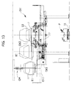
- FIG. 13 is a cross-sectional view showing—at the upper level—the station in which the separation between the already completed body with the parts bolted thereon from the respective pallet, which thus remains empty and free to be taken back to the beginning of the lower section of the line, is carried out;
- FIG. 14 is a variant of FIG. 1 showing a version of the plant where the bolting devices used in the bolting station are actuated manually by the operators.
- a plant for assembling motor-vehicles is indicated in its entirety with reference number 1 .
- the plant 1 comprises a conveying line which follows an endless path in a vertical plane, with a lower section, indicated in its entirety with reference number 1 L, along which pallets P are conveyed in succession in a first direction (from right to left with reference to the drawings) and an upper section, indicated in its entirety with 1 U superimposed at a suitable distance on the lower section 1 L and aligned in the same direction.
- the pallets P move in a direction opposite to the direction of movement of the pallets along the lower section 1 L (i.e. from left to right with reference to the drawings).
- the direction of the movement of the pallets in the plant 1 is indicated by the arrows A in FIG. 1 .
- a vertical transfer station V 1 with a lifting device which lifts a respective pallet P from the lower section 1 L to the upper section 1 U is provided at the final end of the lower section 1 L of the conveying line.
- a vertical transfer station V 2 with a lifting device capable of lowering a respective pallet P from the upper section 1 U to the lower section 1 L is provided at the final end of the upper section 1 U.
- an initially empty pallet P progressively receives the mechanical parts intended to be assembled on a respective motor-vehicle body.
- mechanical parts is used in the present description and in the claims that follow to indicate both the engine of the motor-vehicle as well as any other mechanical part intended to be assembled on the body of the motor-vehicle, such as in particular the front and rear suspension elements, including the springs and the shock absorbers, as well as the transmission components associated to the engine unit.
- a respective pallet P with all the mechanical parts mounted thereon is transferred in the station V 1 to the upper section 1 U, before being moved to a station MX of the upper section where the association (or “marriage”) of a respective body B with the various mechanical parts mounted on the pallet is carried out.
- the bolting means are electric bolting devices carried by manipulating robots R, though it is possible, as observable, to provide for that such bolting be carried out—through manually controlled electric bolting devices—by operators positioned along the lower section 1 L of the line, below the station S.
- a station DX in which the separation (or “divorce”) of a respective body B, with the mechanical parts bolted thereon, from a respective pallet P is provided in the final portion of the upper section 1 U of the line, immediately before the vertical transfer station V 2 .
- the pallet P thus unloaded reaches the vertical transfer station V 2 through which it is lowered to the level of the lower section 1 L, where it is ready again to receive the mechanical parts intended to be bolted on a new body.
- the plant illustrated in FIGS. 1 , 2 is provided to have a high operative flexibility, given that it is capable of simultaneously operating on different types and/or different models and/or versions of motor-vehicles.
- this is achieved by providing a modular architecture for each pallet P, hence allowing easily and quickly adapting each pallet to receive the mechanical parts of the different types of motor-vehicles on which the line is to operate.
- FIG. 3 shows a preferred embodiment for the modular architecture of each pallet P.
- a main pallet element P 1 formed by a base platform in form of a metal framework, or having a front portion P 1 F and a rear portion P 1 R connected to each other by a narrower intermediate portion P 1 I—is provided.
- the pallet structure P further comprises a front sub-pallet SBF and a rear sub-pallet SBR which are coupled and fixed to the base element P 1 at the portions P 1 F and P 1 R thereof.
- Both the sub-pallets SBF,SBR and the intermediate portions P 1 I of the base element P 1 are provided with a plurality of reference supports LO used for the supporting and locating—in the proper assembly position—a plurality of mechanical parts, particularly among which the engine, the front and rear suspension elements and the transmission components of a motor-vehicle.
- each pallet P Due to the previously described modular architecture of each pallet P, the plant 1 according to the invention can be easily adapted to operate on different types or models or versions of motor-vehicles.
- the main base element P 1 of the pallet P is adapted to receive a plurality of different types of front and rear sub-pallets in turn adapted to respective types of motor-vehicles.
- Each of the abovementioned sub-pallets SBF,SBR can in turn be provided both with reference supports LO corresponding to a given type of motor-vehicle and with supports corresponding to another type.
- each sub-pallet SBF is used for loading thereon the front suspension of a corresponding type of motor-vehicle and different types of engines, while the sub-pallet SBR is used for loading different types of rear suspensions.
- the versatility of each sub-pallet in combination with the provision of different types of sub-pallets quickly interchangeable with respect to each other allows obtaining high production flexibility, allowing the use of the plant 1 for the simultaneous production of a plurality of different types/models/versions of motor-vehicles.
- the further great advantage of providing the sub-pallets lies in the fact that the mechanical parts can be pre-mounted thereon off-line, then the mounting on the base element P 1 is carried out with a single and quick operation for each of said sub-pallets.
- the pallet P is preferably provided, both at the intermediate portion P 1 I of the base element P 1 and at the sub-pallets SBF, SBR, with vertical shafts freely rotatable on the pallet (not illustrated), which serve as transmission shafts, which allow bolting various mechanical parts to a respective body by engaging the bolting devices onto the end of said rotatable shafts which project below the pallet.
- vertical shafts freely rotatable on the pallet (not illustrated), which serve as transmission shafts, which allow bolting various mechanical parts to a respective body by engaging the bolting devices onto the end of said rotatable shafts which project below the pallet.
- the means which drive and control the forward movement of the pallets P along the lower section and the upper section 1 L, 1 U of the line can be obtained in any known manner, but preferably they comprise a line of powered rollers, preferably of the type forming an object of the united states patent U.S. Pat. No. 6,966,427, U.S. Pat. No. 7,232,027 owned by the subsidiary company of the Applicant. Still preferably, the forward movement and the precise positioning of the pallets P along the line is obtained by means of devices sold under the “VERSADRIVE” and “VERSACODER” trademarks by the Applicant (see also WO2005005290).
- FIGS. 4-13 of the attached drawings show more in detail and in enlarged scale the main stations of the plant 1 of FIGS. 1 , 2 .
- FIG. 4 illustrates the detail of the vertical transfer station V 2 through which a respective pallet P can be lowered from the level of the upper section 1 U to the level of the lower section 1 L.
- the transfer device for the vertical movement of the pallet at the transfer station V 2 can be of any known type, but in the illustrated case it is specifically of the type forming an object of the European patent EP 1 612 183 B1 of the Applicant, which provides an X-shaped pantograph controlled by a belt winch system.
- the construction details of such device are not illustrated further in FIG. 4 , both for the sake of rendering the latter simpler and clearer and due to the fact that, as mentioned, they are per se known from the previously mentioned prior art document.
- FIG. 4 illustrates the detail of the vertical transfer station V 2 through which a respective pallet P can be lowered from the level of the upper section 1 U to the level of the lower section 1 L.
- the transfer device for the vertical movement of the pallet at the transfer station V 2 can be of any known type, but in the illustrated case it is specifically of
- FIG 4 also shows the part of the plant 1 immediately to the left of the station V 2 (with reference to the drawing) which comprises—at the upper level—a station DX, which shall be described hereinafter, where the separation of the body exiting from the plant is carried out by the respective pallet, while at the lower level it is provided with a waiting station 20 .
- FIG. 5 is an enlarged scale view, according to a section transverse to the longitudinal direction of the line, of the station indicated with 30 in FIG. 1 .
- the station 30 is provided at the beginning of the lower section 1 L of the line with the aim of loading the front sub-pallet SBF by a respective base element P 1 of a pallet.
- a pick-up device 301 (illustrated in FIG. 5 in the various operative positions thereof) which is associated to an overhead conveyor 302 mounted above the station 30 , below the floor of the overlying upper section 1 U of the line is provided in the station 30 for such purpose.
- the overhead conveyor 302 provides for a carriage with wheels 303 movable on elevated tracks extending transversely with respect to the longitudinal direction of the line.
- the pick-up device 301 comprises an X-shaped pantograph 304 bearing—on the lower side thereof—vertical arms 305 provided—at the lower ends thereof—with coupling components 306 of any known type adapted to couple and/or grip a front sub-pallet SBF.
- the construction details related to the overhead conveyor 302 are not illustrated herein in that they may be obtained in any known manner. Same case applies to the lifting device 304 and the control means associated thereto.
- the pick-up device 301 can be moved transversely with respect to the line and positioned both at a position overlying the lower section 1 L of the line (the extreme left position in FIG.
- the conveyor 301 can also be positioned at a maintenance position (the extreme right position in FIG. 5 ) where an operator—on an elevated platform (see FIG. 5 )—performs the required operations.
- FIG. 5 also illustrates a bypass conveyor BY which connects the conveyor 307 of the station 30 to the conveyor 407 (described hereinafter) of the subsequent station 40 .
- FIG. 6 shows, in a transverse section with respect to the longitudinal direction of the line, the subsequent station 40 of the lower section 1 L, where a pick-up device 401 , entirely analogous to the one illustrated in FIG. 5 for the station 30 (illustrated in FIG. 6 in the various operative positions thereof), which loads—on the base element P 1 of the pallet—a new front sub-pallet SBF full of mechanical components previously loaded thereon, is provided.
- the full sub-pallet SBF is picked up by a conveyor 407 (also see FIG. 2B ) used for accumulating the full sub-pallets, and thus unloaded on the element P 1 .
- FIG. 6 the parts corresponding to those of FIG. 5 are indicated using the same reference number, except for the substitution of the initial number 3 with the initial number 4.
- the overhead conveyor 402 is mounted below the floor of the overlying upper section 1 U of the line.
- the pick-up device 401 can be positioned above the line 1 L (extreme left position in FIG. 6 ) for depositing—on the base element P 1 of the pallet—a new front sub-pallet SBF full of mechanical components previously loaded thereon, or above an end of the conveyor 407 (central position in FIG. 6 ), or at a maintenance station, illustrated at the extreme right position in FIG. 6 , where an operator—on an elevated platform—may perform the maintenance operations, in a manner analogous to that described above regarding the station 30 .
- the station 40 also provides for the unloading of an empty rear sub-pallet SBR and the loading of a rear sub-pallet SBR full of mechanical components previously loaded thereon, both operations being performed by means of a manipulating robot R 40 which transfers the rear sub-pallet SBR from the base element P 1 of the pallet P which is located in the line to a conveyor 408 which is located beside the line or, vice versa, from the conveyor 408 to the base element P 1 of the pallets which is located in the line.
- the pick-ups 301 , 401 of the stations 30 and 40 can also be used as mutual back-ups, without affecting the cycle time.
- the bypass conveyor BY directly connecting the conveyors 307 , 407 is primarily used for such purpose.
- a respective pallet P After traversing the stations 30 and 40 , is thus provided with the sub-pallets SBF, SBR and the respective mechanical parts (engine, front suspension and rear suspension).
- the line also allows manually loading other mechanical parts such as silencers, front radiators, and other components depending on the specific requirements of the manufacturer of the motor-vehicles.
- the pallets P which move along the lower section of the line 1 L pass through a passive station, left free to allow performing possible maintenance or back-up interventions and thus through the stations 60 and 70 (see FIGS. 1 , 2 B) which are located below the bolting station S provided at the upper level and which are occupied by the robots R intended to bolt the mechanical parts on the bodies which are located at the upper level.
- a station 80 at which one or more manipulating robots R 80 can be used for further operations, for example providing components such as suspension springs in the proper assembling configuration is provided downstream of the stations 60 , 70 , along the lower section 1 L of the line.
- FIG. 7 also shows the overlying station MX, which shall be illustrated hereinafter.
- the lower section 1 L of the line provides a station 90 which is a control station at which the control of the proper positioning of the mechanical parts to be assembled on the respective body and the configuration of some movable units mounted on the pallet to guarantee the adaptability of the pallet to different models, is carried out.
- control is carried out, according to the invention, by means of an automatic vision system sold under the “VERSAVISION” trademark by the Applicant, which includes a control system adapted to compare the image obtained from a camera with a reference image memorized in the system.
- the vertical transfer station V 1 using a transfer device entirely analogous to that used in the station V 2 described previously, for transferring the pallet P with all the mechanical parts mounted thereon to the level of the upper section 1 U of the line, is provided downstream of the station 90 .
- the pallet P with all the mechanical parts mounted thereon can thus be carried up to a station MX where a respective body is deposited thereon.
- the station MX is provided with a lifting device MX 1 arranged beside the line and provided with forks MX 2 movable transversely on one side or the other of lifting device.
- the lifting device can pick up a body B 1 hooked on hook-like support device H of an overhead line OH and first transfer it above the lifting device MX 1 to a position B 2 and then, through a movement of the forks MX 2 , to the final position B 3 above the pallet, where the body can be lowered on the pallets and on the mechanical parts carried thereby by lowering the lifting device MX 1 .
- four robots RMX guide the shock absorbers and the suspension springs into the respective seats on the body (also see FIG. 2 ).
- FIG. 10 is a cross-section illustrating the bolting station S at which the robot bolting devices R provided at the lower plane engage—from beneath—the lower ends of the transmission shafts freely rotatable on the pallet P which is located at the upper plane, so as to rotate the screws associated to the upper end of such shafts and thus fix the various mechanical parts mounted on the pallet to the body B which is located in the bolting station S.
- FIG. 11 is a cross-section illustrating a subsequent station 150 (also see FIG. 1 ) at which one or more operators can intervene manually to repeat and/or complete the bolting of one or more parts regarding which an improper bolting by the robot R in the station S has been signaled.
- FIG. 12 is a cross-section of a further station 160 at which operators W manually perform bolting operations which require a further intervention from above, to complete the assembly of the mechanical parts.
- FIG. 13 is an enlarged scale cross-sectional view of the “divorce” station DX at which the body with the mechanical parts bolted thereon is separated from the respective pallets P. This is obtained by means of a fork lifting device DX 1 entirely analogous to the lifting device MX 1 provided in the “marriage” station MX. Thus, in FIG. 13 , the parts corresponding to those of FIG. 9 are indicated using the same reference numbers, except for the substitution of letter M with letter D.
- the body the body can be carried from the position B 3 above the line to an intermediate position B 2 through the forks DX 2 and then from such intermediate position B 2 to a position B 1 above a hook-like support device H carried by an overhead conveying line OH, which moves the body with the mechanical parts bolted thereon out of the plant, for the subsequent assembly operations.
- the general architecture of the plant according to the invention is entirely flexible, given that one or more sections of the line which provide robots with sections where manual interventions by the operators are provided for, can be replaced.
- An example of this type is illustrated in FIG. 14 where the plant includes a line section ML where the various mechanical parts are loaded manually on the pallets which move along the lower section of the line, and a section MB where the operation of bolting the mechanical parts on the bodies which move along the upper section of the line is carried out manually.
- the plant according to the invention attains a considerable improvement with respect to the previous solution proposed by the Applicant (GB2136330A) in terms of reducing the occupied space, greater operative efficiency due to the reduction of the “passive” parts of the lines, flexibility due to the modular architecture of each pallet as well as the modular architecture of the entire line and easy accessibility of each station of the line from both sides thereof, to the advantage of logistics regarding the supply of the parts.
- the provision of the line for assembling the mechanical parts on the pallet and the bolting line at a position superimposed over each other allows a more rational use of different assembly stations. Furthermore, excavation of pits into the floor to receive the means required for bolting is not necessary.
- the plant according to the invention is suitable for using devices of any known type regarding the means for moving the pallets within the plant
- the motorized roller conveyor line which represents a production standard of the Applicant company, with control and position systems sold under the “VERSADRIVE” and “VERSACODER” trademarks, and with the further provision of a control of the proper execution of the assembly operations through the automatic vision system sold by the Applicant under the “VERSAVISION” trademark is particularly preferred.
Landscapes
- Engineering & Computer Science (AREA)
- Mechanical Engineering (AREA)
- Manufacturing & Machinery (AREA)
- Chemical & Material Sciences (AREA)
- Combustion & Propulsion (AREA)
- Transportation (AREA)
- Automatic Assembly (AREA)
- Automobile Manufacture Line, Endless Track Vehicle, Trailer (AREA)
- Warehouses Or Storage Devices (AREA)
Priority Applications (1)
| Application Number | Priority Date | Filing Date | Title |
|---|---|---|---|
| US14/700,995 US9259815B2 (en) | 2009-12-30 | 2015-04-30 | Plant for assembling mechanical parts on bodies of motor-vehicles |
Applications Claiming Priority (3)
| Application Number | Priority Date | Filing Date | Title |
|---|---|---|---|
| ITTO2009A001054 | 2009-12-30 | ||
| ITTO2009A001054A IT1397438B1 (it) | 2009-12-30 | 2009-12-30 | Installazione per l'assemblaggio di parti meccaniche su scocche di autoveicoli |
| ITTO2009A1054 | 2009-12-30 |
Related Child Applications (1)
| Application Number | Title | Priority Date | Filing Date |
|---|---|---|---|
| US14/700,995 Continuation US9259815B2 (en) | 2009-12-30 | 2015-04-30 | Plant for assembling mechanical parts on bodies of motor-vehicles |
Publications (2)
| Publication Number | Publication Date |
|---|---|
| US20110154654A1 US20110154654A1 (en) | 2011-06-30 |
| US9045182B2 true US9045182B2 (en) | 2015-06-02 |
Family
ID=42398234
Family Applications (2)
| Application Number | Title | Priority Date | Filing Date |
|---|---|---|---|
| US12/973,265 Active 2031-10-08 US9045182B2 (en) | 2009-12-30 | 2010-12-20 | Plant for assembling mechanical parts on bodies of motor-vehicles |
| US14/700,995 Active US9259815B2 (en) | 2009-12-30 | 2015-04-30 | Plant for assembling mechanical parts on bodies of motor-vehicles |
Family Applications After (1)
| Application Number | Title | Priority Date | Filing Date |
|---|---|---|---|
| US14/700,995 Active US9259815B2 (en) | 2009-12-30 | 2015-04-30 | Plant for assembling mechanical parts on bodies of motor-vehicles |
Country Status (8)
| Country | Link |
|---|---|
| US (2) | US9045182B2 (de) |
| EP (1) | EP2340982B1 (de) |
| CN (1) | CN102114594B (de) |
| BR (1) | BRPI1005531B1 (de) |
| ES (1) | ES2392149T3 (de) |
| IT (1) | IT1397438B1 (de) |
| MX (1) | MX2010014313A (de) |
| PL (1) | PL2340982T3 (de) |
Cited By (4)
| Publication number | Priority date | Publication date | Assignee | Title |
|---|---|---|---|---|
| US20150047184A1 (en) * | 2012-03-19 | 2015-02-19 | CPM S.p.A | Plant for assembling mechanical parts on vehicle bodies |
| US9561910B1 (en) * | 2016-02-08 | 2017-02-07 | Lear Corporation | Vertical assembly line |
| US9908575B2 (en) * | 2013-07-05 | 2018-03-06 | Torsten Hösker | Overhead conveying device having support framework modules |
| US10441993B2 (en) | 2015-09-11 | 2019-10-15 | Lear Corporation | Vertical twisting system and method |
Families Citing this family (20)
| Publication number | Priority date | Publication date | Assignee | Title |
|---|---|---|---|---|
| JP5748452B2 (ja) * | 2010-11-15 | 2015-07-15 | キヤノン株式会社 | 部品組立システム |
| DE102010055959A1 (de) * | 2010-12-23 | 2012-06-28 | Daimler Ag | Verfahren zum Montieren von Kraftwagen |
| DE102012214127A1 (de) * | 2012-08-09 | 2014-02-13 | Torsten Hösker | Überflurfördereinrichtung mit selbsttragendem Traggerüst |
| CN102814644A (zh) * | 2012-09-10 | 2012-12-12 | 苏州美尔科自动化设备有限公司 | 一种血液透析器的自动化组装设备 |
| JP5741618B2 (ja) * | 2013-03-19 | 2015-07-01 | 株式会社安川電機 | ワークの組立装置及び組立方法 |
| DE102013213223A1 (de) * | 2013-07-05 | 2015-01-08 | Torsten Hösker | Überflurfördereinrichtung mit Sicherungselement |
| DE202013104354U1 (de) * | 2013-09-24 | 2013-10-10 | Torsten Hösker | Überflurfördereinrichtung zur Lagerung an der Decke einer Montageanlage |
| US20150128719A1 (en) * | 2013-11-12 | 2015-05-14 | Comau, Inc. | Assembly line quality control cart and method |
| CN103659267B (zh) * | 2013-12-19 | 2016-04-06 | 周俊雄 | 调节器的中壳体组件自动组装机 |
| DE202014101003U1 (de) * | 2014-03-06 | 2015-06-17 | Kuka Systems Gmbh | Fertigungsanlage |
| CN106103006B (zh) * | 2014-03-06 | 2019-03-29 | 库卡系统有限责任公司 | 制造工作站,制造设备和方法 |
| EP2923925A3 (de) | 2014-03-27 | 2016-01-13 | Cpm S.P.A. | Universeller gleichgewichtshalter zum transportieren von fahrzeugkarosserien und transportanlage damit |
| CN107585225B (zh) * | 2017-09-25 | 2023-05-12 | 郑州日产汽车有限公司 | 承载与非承载式车身车型混流装配生产线 |
| IT201900007971A1 (it) | 2019-06-04 | 2020-12-04 | Cpm S P A | Convogliatore ed impianto di convogliamento provvisto di tale convogliatore, in particolare per linee di assemblaggio di veicoli |
| US10822043B1 (en) | 2019-06-06 | 2020-11-03 | Mahindra N.A. Tech Center | Method of interconnecting a chassis and a body |
| CN110666809A (zh) * | 2019-09-19 | 2020-01-10 | 浙江科技学院 | 一种植树机器人 |
| IT202000016303A1 (it) | 2020-07-06 | 2022-01-06 | Cpm S P A | Mandrino di avvitatura per un impianto di assemblaggio veicoli e pallet associato attrezzato con lo stesso |
| IT202000016309A1 (it) | 2020-07-06 | 2022-01-06 | Cpm S P A | Mandrino di avvitatura ad avanzamento guidato per un impianto di assemblaggio veicoli e pallet associato attrezzato con lo stesso |
| CN113560870B (zh) * | 2021-09-17 | 2024-10-22 | 佛山市和阳精密金属制品有限公司 | 一种自动装配线 |
| CN116944862B (zh) * | 2023-08-07 | 2025-10-31 | 中航星网机电科技(河北)有限公司 | 一种火工品自动化装配系统 |
Citations (18)
| Publication number | Priority date | Publication date | Assignee | Title |
|---|---|---|---|---|
| US2804962A (en) * | 1955-09-12 | 1957-09-03 | Smith Corp A O | Apparatus for automatically fabricating vehicle frames |
| US3968559A (en) * | 1972-05-19 | 1976-07-13 | Ab Volvo | Method and arrangement for assembly of component parts, preferably for motor vehicles |
| GB2136330A (en) | 1983-03-04 | 1984-09-19 | Comau Spa | Programmable System for the Screwing of Various Mechanical Parts of Motor Vehicles to the Respective Bodies |
| US5397047A (en) * | 1993-09-20 | 1995-03-14 | Comau S.P.A. | Device for spot welding of structures constituted by sheet metal elements, particularly motor-vehicle bodies |
| EP0751161A2 (de) | 1995-06-30 | 1997-01-02 | MITSUI TOATSU CHEMICALS, Inc. | Schwefel enthaltende Harzzusammensetzung auf Urethanbasis sowie optisches Element und Linse, die daraus hergestellt sind |
| DE29721038U1 (de) | 1997-11-28 | 1999-04-01 | Ekuma Werkzeug- und Maschinenbau GmbH, 66663 Merzig | Anlage zum Einbauen von Fahrzeugteilen in eine Karosserie |
| US6109424A (en) * | 1997-03-20 | 2000-08-29 | Fori Automation, Inc. | Chassis/body marriage lift machine |
| US6145180A (en) * | 1990-12-28 | 2000-11-14 | Mazda Motor Corporation | Method and system for the assembly of works and method for the assembly of automotive vehicles |
| US6494304B1 (en) * | 2000-08-15 | 2002-12-17 | Jervis B. Webb Company | Production operation with power and free pallet conveyor |
| US6554119B2 (en) * | 2000-02-07 | 2003-04-29 | Progressive Tool & Industries Co. | Flexible automotive assembly line and method |
| US20040195077A1 (en) | 2003-04-04 | 2004-10-07 | Velibor Kilibarda | Pallet/skid power roll system |
| US6835909B2 (en) * | 2001-09-26 | 2004-12-28 | Nissan Motor Co., Ltd. | Method and apparatus of assembling vehicular body |
| WO2005005290A2 (en) | 2003-06-30 | 2005-01-20 | Progressive Tool & Industries, Co. | A precise transport posiitoning apparatus using a closed loop controlled, non-direct drive or friction drive system with absolute positioning encoder |
| EP1612183A1 (de) | 2004-06-29 | 2006-01-04 | COMAU S.p.A. | Lasthebevorrichtung |
| US6991087B2 (en) * | 2001-04-28 | 2006-01-31 | Duerr Systems Gmbh | Conveyor device for advancing work-pieces through a processing zone for the surface treatment of the work-pieces |
| US20060167587A1 (en) * | 2001-10-18 | 2006-07-27 | Dale Read | Auto Motion: Robot Guidance for Manufacturing |
| US7469473B2 (en) * | 2006-06-28 | 2008-12-30 | Utica Enterprises, Inc. | Assembly line vehicle body positioning |
| US20100263801A1 (en) * | 2005-01-18 | 2010-10-21 | Android Industries Llc | Inflation Work Station |
Family Cites Families (5)
| Publication number | Priority date | Publication date | Assignee | Title |
|---|---|---|---|---|
| DE19523294A1 (de) * | 1995-06-27 | 1997-01-02 | Opel Adam Ag | Anlage zum Fügen der Chassis-Aggregate mit der Karosserie eines Kraftfahrzeuges |
| CA2531090A1 (en) * | 2003-07-01 | 2005-01-13 | Honda Motor Co., Ltd. | Device and method of transporting and installing component |
| PL1880795T3 (pl) * | 2006-07-19 | 2009-04-30 | Comau Spa | Komórka do zautomatyzowanych operacji montażowych |
| KR100792891B1 (ko) * | 2006-10-10 | 2008-01-08 | 현대자동차주식회사 | 다차종 프론트 엔드 모듈의 조립용 지그장치 |
| CN101311054A (zh) * | 2007-05-25 | 2008-11-26 | 南通中集特种运输设备制造有限公司 | 运车平台的装配方法及其工作台 |
-
2009
- 2009-12-30 IT ITTO2009A001054A patent/IT1397438B1/it active
-
2010
- 2010-12-07 ES ES10193941T patent/ES2392149T3/es active Active
- 2010-12-07 PL PL10193941T patent/PL2340982T3/pl unknown
- 2010-12-07 EP EP10193941A patent/EP2340982B1/de active Active
- 2010-12-20 MX MX2010014313A patent/MX2010014313A/es active IP Right Grant
- 2010-12-20 US US12/973,265 patent/US9045182B2/en active Active
- 2010-12-23 BR BRPI1005531-2A patent/BRPI1005531B1/pt active IP Right Grant
- 2010-12-30 CN CN201010614104.3A patent/CN102114594B/zh active Active
-
2015
- 2015-04-30 US US14/700,995 patent/US9259815B2/en active Active
Patent Citations (21)
| Publication number | Priority date | Publication date | Assignee | Title |
|---|---|---|---|---|
| US2804962A (en) * | 1955-09-12 | 1957-09-03 | Smith Corp A O | Apparatus for automatically fabricating vehicle frames |
| US3968559A (en) * | 1972-05-19 | 1976-07-13 | Ab Volvo | Method and arrangement for assembly of component parts, preferably for motor vehicles |
| GB2136330A (en) | 1983-03-04 | 1984-09-19 | Comau Spa | Programmable System for the Screwing of Various Mechanical Parts of Motor Vehicles to the Respective Bodies |
| US6145180A (en) * | 1990-12-28 | 2000-11-14 | Mazda Motor Corporation | Method and system for the assembly of works and method for the assembly of automotive vehicles |
| US5397047A (en) * | 1993-09-20 | 1995-03-14 | Comau S.P.A. | Device for spot welding of structures constituted by sheet metal elements, particularly motor-vehicle bodies |
| EP0751161A2 (de) | 1995-06-30 | 1997-01-02 | MITSUI TOATSU CHEMICALS, Inc. | Schwefel enthaltende Harzzusammensetzung auf Urethanbasis sowie optisches Element und Linse, die daraus hergestellt sind |
| US6109424A (en) * | 1997-03-20 | 2000-08-29 | Fori Automation, Inc. | Chassis/body marriage lift machine |
| DE29721038U1 (de) | 1997-11-28 | 1999-04-01 | Ekuma Werkzeug- und Maschinenbau GmbH, 66663 Merzig | Anlage zum Einbauen von Fahrzeugteilen in eine Karosserie |
| US6554119B2 (en) * | 2000-02-07 | 2003-04-29 | Progressive Tool & Industries Co. | Flexible automotive assembly line and method |
| US6494304B1 (en) * | 2000-08-15 | 2002-12-17 | Jervis B. Webb Company | Production operation with power and free pallet conveyor |
| US6991087B2 (en) * | 2001-04-28 | 2006-01-31 | Duerr Systems Gmbh | Conveyor device for advancing work-pieces through a processing zone for the surface treatment of the work-pieces |
| US6835909B2 (en) * | 2001-09-26 | 2004-12-28 | Nissan Motor Co., Ltd. | Method and apparatus of assembling vehicular body |
| US20060167587A1 (en) * | 2001-10-18 | 2006-07-27 | Dale Read | Auto Motion: Robot Guidance for Manufacturing |
| US20040195077A1 (en) | 2003-04-04 | 2004-10-07 | Velibor Kilibarda | Pallet/skid power roll system |
| US6966427B2 (en) | 2003-04-04 | 2005-11-22 | Progressive Tool & Industries Co. | Pallet/skid power roll system |
| US20050241915A1 (en) | 2003-04-04 | 2005-11-03 | Progressive Tool & Industries, Co. | Pallet/skid power roll system |
| US7232027B2 (en) | 2003-04-04 | 2007-06-19 | Comau, Inc. | Pallet/skid power roll system |
| WO2005005290A2 (en) | 2003-06-30 | 2005-01-20 | Progressive Tool & Industries, Co. | A precise transport posiitoning apparatus using a closed loop controlled, non-direct drive or friction drive system with absolute positioning encoder |
| EP1612183A1 (de) | 2004-06-29 | 2006-01-04 | COMAU S.p.A. | Lasthebevorrichtung |
| US20100263801A1 (en) * | 2005-01-18 | 2010-10-21 | Android Industries Llc | Inflation Work Station |
| US7469473B2 (en) * | 2006-06-28 | 2008-12-30 | Utica Enterprises, Inc. | Assembly line vehicle body positioning |
Non-Patent Citations (1)
| Title |
|---|
| Italian Search Report, Dated Aug. 9, 2010. |
Cited By (6)
| Publication number | Priority date | Publication date | Assignee | Title |
|---|---|---|---|---|
| US20150047184A1 (en) * | 2012-03-19 | 2015-02-19 | CPM S.p.A | Plant for assembling mechanical parts on vehicle bodies |
| US9533725B2 (en) * | 2012-03-19 | 2017-01-03 | Cpm S.P.A. | Plant for assembling mechanical parts on vehicle bodies |
| US9908575B2 (en) * | 2013-07-05 | 2018-03-06 | Torsten Hösker | Overhead conveying device having support framework modules |
| US10441993B2 (en) | 2015-09-11 | 2019-10-15 | Lear Corporation | Vertical twisting system and method |
| US9561910B1 (en) * | 2016-02-08 | 2017-02-07 | Lear Corporation | Vertical assembly line |
| WO2017138989A1 (en) * | 2016-02-08 | 2017-08-17 | Lear Corporation | Vertical assembly line |
Also Published As
| Publication number | Publication date |
|---|---|
| US20110154654A1 (en) | 2011-06-30 |
| CN102114594A (zh) | 2011-07-06 |
| BRPI1005531B1 (pt) | 2020-07-14 |
| IT1397438B1 (it) | 2013-01-10 |
| EP2340982B1 (de) | 2012-09-19 |
| US20150239078A1 (en) | 2015-08-27 |
| MX2010014313A (es) | 2011-07-27 |
| US9259815B2 (en) | 2016-02-16 |
| CN102114594B (zh) | 2016-01-20 |
| ITTO20091054A1 (it) | 2011-06-30 |
| BRPI1005531A2 (pt) | 2013-10-22 |
| PL2340982T3 (pl) | 2013-01-31 |
| EP2340982A1 (de) | 2011-07-06 |
| ES2392149T3 (es) | 2012-12-05 |
Similar Documents
| Publication | Publication Date | Title |
|---|---|---|
| US9045182B2 (en) | Plant for assembling mechanical parts on bodies of motor-vehicles | |
| CN111906531B (zh) | 电力机车轮驱单元装配线 | |
| KR101198662B1 (ko) | 자동차용 사이드패널 생산시스템 | |
| CN104321161B (zh) | 车身用部件安装系统 | |
| US12522444B2 (en) | Vehicle servicing apparatus and methods of use thereof | |
| US9944336B2 (en) | Part installation machine | |
| CN108673089B (zh) | 一种涂装积放链直接用于装配的多工位装配系统 | |
| EP3748081A1 (de) | Schienenwagen zum bewegen von schwellen, schienenfahrzeug mit derartigem schienenwagen | |
| WO2012169321A1 (ja) | 車体組立ライン及びそれを用いた車体組立方法 | |
| CN113844568A (zh) | 一种基于agv的柔性化总装车间工艺线路结构 | |
| JP2011000702A (ja) | 工程間フレキシブル自動搬送システム | |
| CN108928407B (zh) | 一种报废车辆的拆解流水线及拆解方法 | |
| JP2012533469A (ja) | システムを実装するための方法及び装置、並びに貨物積載システム | |
| CN115231269B (zh) | 一种生产单元、自动化针车生产线及生产方法 | |
| CN112026960A (zh) | 一种新能源商用车总装车间线路布局 | |
| CN108995570B (zh) | 一种构件转运车及转运系统 | |
| CN109733808B (zh) | 分层式车钩环形存放传输线 | |
| KR20100087973A (ko) | 펜더 조립용 지그 장치 | |
| JPS63247179A (ja) | 車両の組立装置 | |
| CN114852728B (zh) | 智能厢式车辆装车、卸车机器人 | |
| CN210212346U (zh) | 电池包运输装置以及换电站 | |
| WO2017105218A1 (en) | Device, assembly and method for loading a vehicle with loaded pallets | |
| JP2910864B2 (ja) | パレット入替装置 | |
| KR20040039121A (ko) | 부품 이송용 스토리지 장치 | |
| JPH10264870A (ja) | 自動車製造ライン及び自動車搬送方法 |
Legal Events
| Date | Code | Title | Description |
|---|---|---|---|
| AS | Assignment |
Owner name: COMAU S.P.A, ITALY Free format text: ASSIGNMENT OF ASSIGNORS INTEREST;ASSIGNORS:CARDANI, SERGIO;RUMIANO, GUIDO;PUTIRI, ANGELO;REEL/FRAME:025688/0797 Effective date: 20101222 |
|
| FEPP | Fee payment procedure |
Free format text: PAYOR NUMBER ASSIGNED (ORIGINAL EVENT CODE: ASPN); ENTITY STATUS OF PATENT OWNER: LARGE ENTITY |
|
| STCF | Information on status: patent grant |
Free format text: PATENTED CASE |
|
| FEPP | Fee payment procedure |
Free format text: MAINTENANCE FEE REMINDER MAILED (ORIGINAL EVENT CODE: REM.); ENTITY STATUS OF PATENT OWNER: LARGE ENTITY |
|
| FEPP | Fee payment procedure |
Free format text: SURCHARGE FOR LATE PAYMENT, LARGE ENTITY (ORIGINAL EVENT CODE: M1554); ENTITY STATUS OF PATENT OWNER: LARGE ENTITY |
|
| MAFP | Maintenance fee payment |
Free format text: PAYMENT OF MAINTENANCE FEE, 4TH YEAR, LARGE ENTITY (ORIGINAL EVENT CODE: M1551); ENTITY STATUS OF PATENT OWNER: LARGE ENTITY Year of fee payment: 4 |
|
| MAFP | Maintenance fee payment |
Free format text: PAYMENT OF MAINTENANCE FEE, 8TH YEAR, LARGE ENTITY (ORIGINAL EVENT CODE: M1552); ENTITY STATUS OF PATENT OWNER: LARGE ENTITY Year of fee payment: 8 |
|
| AS | Assignment |
Owner name: CPM S.P.A., ITALY Free format text: NUNC PRO TUNC ASSIGNMENT;ASSIGNOR:COMAU S.P.A.;REEL/FRAME:066818/0208 Effective date: 20240220 |