US9059628B2 - Energy harvesting - Google Patents
Energy harvesting Download PDFInfo
- Publication number
- US9059628B2 US9059628B2 US13/773,571 US201313773571A US9059628B2 US 9059628 B2 US9059628 B2 US 9059628B2 US 201313773571 A US201313773571 A US 201313773571A US 9059628 B2 US9059628 B2 US 9059628B2
- Authority
- US
- United States
- Prior art keywords
- supporting structure
- coil
- magnet
- motion
- vehicle
- Prior art date
- Legal status (The legal status is an assumption and is not a legal conclusion. Google has not performed a legal analysis and makes no representation as to the accuracy of the status listed.)
- Active, expires
Links
Images




Classifications
-
- H02K57/003—
-
- H—ELECTRICITY
- H02—GENERATION; CONVERSION OR DISTRIBUTION OF ELECTRIC POWER
- H02K—DYNAMO-ELECTRIC MACHINES
- H02K35/00—Generators with reciprocating, oscillating or vibrating coil system, magnet, armature or other part of the magnetic circuit
- H02K35/02—Generators with reciprocating, oscillating or vibrating coil system, magnet, armature or other part of the magnetic circuit with moving magnets and stationary coil systems
-
- H—ELECTRICITY
- H02—GENERATION; CONVERSION OR DISTRIBUTION OF ELECTRIC POWER
- H02K—DYNAMO-ELECTRIC MACHINES
- H02K35/00—Generators with reciprocating, oscillating or vibrating coil system, magnet, armature or other part of the magnetic circuit
- H02K35/04—Generators with reciprocating, oscillating or vibrating coil system, magnet, armature or other part of the magnetic circuit with moving coil systems and stationary magnets
-
- H—ELECTRICITY
- H02—GENERATION; CONVERSION OR DISTRIBUTION OF ELECTRIC POWER
- H02K—DYNAMO-ELECTRIC MACHINES
- H02K7/00—Arrangements for handling mechanical energy structurally associated with dynamo-electric machines, e.g. structural association with mechanical driving motors or auxiliary dynamo-electric machines
- H02K7/18—Structural association of electric generators with mechanical driving motors, e.g. with turbines
- H02K7/1807—Rotary generators
- H02K7/1846—Rotary generators structurally associated with wheels or associated parts
-
- H—ELECTRICITY
- H02—GENERATION; CONVERSION OR DISTRIBUTION OF ELECTRIC POWER
- H02K—DYNAMO-ELECTRIC MACHINES
- H02K7/00—Arrangements for handling mechanical energy structurally associated with dynamo-electric machines, e.g. structural association with mechanical driving motors or auxiliary dynamo-electric machines
- H02K7/18—Structural association of electric generators with mechanical driving motors, e.g. with turbines
- H02K7/1807—Rotary generators
- H02K7/1853—Rotary generators driven by intermittent forces
-
- H01L2924/00—
-
- H01L2924/0002—
Definitions
- the disclosure relates generally to power harvesting, and in particular to a new and innovative device and method for harvesting power from the motion of an object, such as a vehicle.
- Wireless sensor systems are becoming increasingly important for multiple applications ranging from security to predictive and condition-based maintenance in a wide variety of applications.
- Vehicles form one class of systems of particular interest for such monitoring, as they of necessity include many components which are subject to motion, wear, and stress during operation.
- Such wireless sensor systems require a source of power.
- Providing a wired power source significantly reduces the utility of most wireless monitoring applications, while batteries will eventually become exhausted and need to be replaced; this represents significant time and effort and may be very difficult to impossible in some wireless sensor settings (for instance, if a wireless sensor is to be embedded in a component to provide lifetime monitoring).
- Power harvesting deriving energy for the sensor from some aspect of the sensor's environment—has thus been of considerable interest to the industry.
- Berkcan et al describe a harvesting system comprised of cantilevers of varying resonant lengths which generate energy through vibration by piezoelectric transduction.
- Rastegar in U.S. Pat. No. 7,821,183 B2, describes a system which uses motion of some mass to in turn excite cantilevered piezoelectric beams which generate electrical energy.
- Gao et al in U.S. Pat. No. 7,936,109 B1, describe another method in which a piezoelectric element on a bendable substrate collides with a housing through which it moves, thereby generating energy.
- An embodiment of the current invention provides a non-resonance dependent, widely applicable solution to harvest milliwatt-scale energy in a broad range of frequencies, including those in the fractional hertz range, which may be found on various vehicles including but not limited to train cars, trucks, and ocean-going vessels.
- the current invention can address one or more limitations of the described prior art to provide a reliable, broad-band solution for maintaining a power supply for a wireless system or other system which requires a reliable low-power supply, or which will very intermittently use much more power but recharge slowly in the intervening time.
- aspects of the invention can provide improvement in capability and can result in the harvesting of energy on the order of a milliwatt or so from various types of movement in vehicular or other similar settings.
- the energy can be harvested in a non-resonance dependent manner and may harvest energy across a broad spectrum of vibrations and oscillations.
- a first aspect of the invention provides a device for energy harvesting from motion of an object, the device comprising: at least one magnet; at least one coil; a magnet supporting structure supporting the at least one magnet; a coil supporting structure supporting the at least one coil, wherein the magnet supporting structure and the coil supporting structure enable movement of the at least one magnet relative to the at least one coil during operation of the object, and wherein at least one of the magnet supporting structure or the coil supporting structure is configured to be affixed to the object; and means for providing a restoring force to at least one of: the magnet supporting structure or the coil supporting structure.
- Various electronics may be attached to the coil or coils to store or make use of the energy generated from the device.
- a second aspect of the invention provides a method for energy harvesting comprising: moving a magnet supporting structure with respect to a coil supporting structure based on motion of an object to which the coil supporting structure is affixed, wherein at least one of the magnet supporting structure or the coil supporting structure is configured to provide a restoring force to maintain a relative difference in motion between the magnet supporting structure and the coil supporting structure without regard to resonant phenomena; and generating electrical energy based on the relative motion between at least one magnet corresponding to the magnet supporting structure and at least one coil corresponding to the coil supporting structure.
- a third aspect of the invention provides a vehicle including: a device for energy harvesting from motion of the vehicle, the device comprising: at least one magnet; at least one coil; a magnet supporting structure supporting the at least one magnet; a coil supporting structure supporting the at least one coil, wherein the magnet supporting structure and the coil supporting structure enable movement of the at least one magnet relative to the at least one coil during operation of the vehicle, and wherein at least one of the magnet supporting structure or the coil supporting structure is affixed to the vehicle; and means for providing a restoring force to at least one of: the magnet supporting structure or the coil supporting structure.
- the illustrative aspects of the invention are designed to solve one or more of the problems herein described and/or one or more other problems not discussed.
- FIG. 1 shows a view of an illustrative device according to an embodiment of the invention in basic concept.
- FIG. 1 a shows a front view of the device and
- FIG. 1 b shows a side view of the device.
- FIG. 2 shows a conceptual diagram of an illustrative device according to a second embodiment of the invention for use, for example, on the hub of a railroad car.
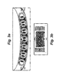
- FIGS. 3 a and 3 b show a conceptual diagram of an illustrative device according to a third embodiment of the invention for use in harvesting energy from long-period motions.
- FIG. 4 shows a conceptual diagram of an illustrative device according to a fourth embodiment of the invention for use, for example, in harvesting energy from the suspension of a vehicle.
- FIGS. 5 a and 5 b show a conceptual diagram of an illustrative device according to a fifth embodiment of the invention which provides a means to increase the voltage and potentially overall power harvested by the device.
- FIG. 6 shows a conceptual diagram of an illustrative method to control behavior of an energy harvesting device under different levels of excitation according to an embodiment.
- aspects of the invention provide a device comprising at least one magnet, at least one coil, at least one magnet containing or holding structure, at least one coil containing or holding structure, and a component or design element to provide a restoring force to either the magnet containing or holding structure or the coil containing or holding structure.
- Various electronics may be attached to the coil or coils to store or make use of the energy generated from the device.
- the coil containing or holding structure could be the structure to move and be subjected to the restoring force.
- connections which would either move with the coil-containing or holding structure or be able to transfer the electrical power from a moving object—e.g., slip rings or a continuous electrical contact or similar arrangements, would be required.
- such connections may either introduce significant potential physical damping (e.g., from connected wires that would have to be bent or moved with the coils) and/or points of failure from these connections, or may introduce additional contact resistance and friction issues.
- the magnet containing or holding structure is the component which is free to move relative to the coils.
- the coils may move relative to the magnet, but the electrical connections and vehicle or object to which the entire device is attached will be stationary with respect to the coils.
- FIG. 1 An illustrative embodiment of the invention is shown in FIG. 1 , and can harvest energy from the motion of a vehicle, such as a railroad car.
- FIGS. 1 a and 1 b show an illustrative energy-harvesting device 100 according to an embodiment.
- the device 100 is comprised of harvesting coils 102 , which are affixed to a coil supporting structure (coil framework) 104 .
- a set of magnets 106 is attached to a separate magnet supporting structure (magnet framework) 108 , which is supported by a hub 110 .
- the coil framework 104 is pivotally attached to the magnet framework 108 .
- hub 110 includes a bearing which allows the framework 108 to rotate with respect to coil framework 104 .
- Attached to the framework 108 is a weight 112 .
- Weight 112 provides a restoring force for any force that attempts to rotate the magnet framework 108 with respect to the coil framework 104 .
- coil framework 104 when coil framework 104 is affixed to an object, such as a vehicle, which oscillates in the plane of the coil framework 104 and magnet framework 108 during operation, the coil framework 104 will oscillate along with the object to which it is attached. However, the magnet framework 108 is free to rotate in this plane, and due to inertia will tend to remain in its original orientation throughout the object's oscillations, modulo the slight force transmitted to magnet framework 108 through the bearing of hub 110 . However, this slight force will be opposed by the restoring force of weight 112 ; this will minimize any motion of magnet framework 108 . The net effect, then, is that the magnets 106 move with respect to the coils 102 with any oscillation of the object and thus coil framework 104 .
- the designs of the rotor or framework 104 e.g., the number of coils 102 , the number of turns in coils 102 , and/or the like
- the stator or framework 108 e.g., the strength of magnets 106 , geometry of the framework 108 , and/or the like
- harvester power conditioning systems for low voltage inputs such as Cymbet's “EnerChipTM” systems or those offered by Advanced Linear Devices, permit effective collection and harvesting of energy from potentials as low as tens of millivolts and a few hundred nanoamps, which makes harvesting at very low voltages practical.
- An embodiment of the designs and approaches described herein can cover oscillation ranges from near-zero (e.g., small fractional Hz, very long-wave motion) and up to ten or twenty Hertz.
- An ability to operate at such oscillation ranges can enable use of the device on large vehicles, whose general oscillations in most dimensions can be between 0.25 Hz and 3-4 Hz.
- the coils can be designed as larger annular shapes, which can maximize the dB/dt*(a term that increases power generation); the design element which produces restoring force also can be significantly larger or more effective in order to prevent the action of generating power from reducing or stopping the relative motion of the magnets and coils due to Lorentz forces.
- a device is designed to fit on the end of a rotating shaft of an object/structure; for example, the axle of a railcar.
- FIG. 2 illustrates one conceptual design for such a device.
- magnets 130 and a weight 132 are affixed to a support structure 134 that is itself attached to a low-friction bearing 136 which allows the weight 132 to keep the support structure 134 in its same general orientation even if the remainder of the device is rotating.
- a set of coils 138 are affixed to a shaft 140 ; the bearing 136 surrounds the shaft 140 .
- the entire device is enclosed within a housing 142 which can protect the device from environmental and physical stresses and which may also contain the electronics which will make use of the generated power.
- the housing 142 can be affixed to the end of the axle 144 .
- the housing 142 and all components within also rotate at the same rate, except for the magnet support structure 134 which is generally maintained in a constant orientation by the weight 132 and the turning of the low-friction bearing 136 . Because of this maintained orientation, the coils 138 rotate relative to the magnets and thus generate electrical power.
- FIG. 3 a and FIG. 3 b A conceptual version of this embodiment is shown in FIG. 3 a and FIG. 3 b .
- a set of coils 160 are spaced along the sides of an enclosure 162 .
- the bottom of the enclosure 162 is curved up at both ends and the coils 160 follow the curve; the enclosure 162 can serve both as rugged protection for the device (and potentially for any electronics associated with the device) and as support for the various components of the device.
- a set of magnets 164 are within the enclosure 162 ; the magnets 164 are cylindrical in this embodiment although other shapes such as a sphere may be used in a similar design.
- the magnets 164 can be sized and spaced such that their spacing and overall cross-sectional size generally corresponds with that of the coils 160 .
- the spacing can be maintained by a bearing frame 166 which allows the magnets 164 to roll with minimal impediment but prevents the magnets 164 from impacting with or sticking to each other.
- the magnets 164 can roll on a track or rail 168 which is attached to the enclosure 162 , and which can be located at a height which will cause the magnets 164 to roll along the centerlines of the coils 160 .
- the magnets 164 roll up and down the curved rails 168 , moving relative to the coils 160 and generating electrical power.
- the design element providing the restoring force is the curved portion of the enclosure 162 rather than a weight as in other embodiments.
- FIG. 4 Another embodiment of the invention involves attaching the magnet and coil components to different portions of an object, such as a vehicle, which undergo relative motion; for example, the spring and supports of a suspension.
- magnets 190 are spaced along a support 192 .
- Support 192 is attached to the spring 194 of the vehicle (e.g., a railcar) suspension.
- the magnets ride within an enclosure 196 , which has a slit or other means to allow the support 192 to move up and down relative to the enclosure 196 which is affixed to vehicle support structure 198 .
- a coil or coils 200 are either part of, or placed immediately surrounding, enclosure 196 .
- the spring 194 is compressed and released as the vehicle travels, dependent on load, smoothness of surface (e.g., track, road, or the like), rocking of the vehicle, and other factors. Compression of the spring 194 causes the magnet support 192 to drop relative to the enclosure 196 , while relaxation or release of the spring 194 causes the support 192 to rise relative to the enclosure 196 .
- a level of the attachment of the support 192 to the spring 194 can be selected such that a minimum load of the vehicle will place the support 192 at or below the maximum allowable travel along the slit in enclosure 196 .
- the restoring force is provided by the separation of the two key components to attachments with external components which have a limited and known mobility with respect to each other.
- FIGS. 5 a and 5 b show a conceptual diagram of this embodiment of the invention.
- a pendulum 220 comprised of a weight 222 and an arm 224 is attached to a large gear 226 .
- Large gear 226 meshes with a small gear 228 .
- Small gear 228 is attached to the shaft of miniature generator 230 , causing the rotor of the generator 230 to turn.
- the weighted pendulum is the design element providing the restoring force of the presented invention.
- the multiple revolutions of the generator 230 generate a significant alternating current 232 .
- This approach addresses one of the challenges of the invention which is that low-speed movement of magnets past coils tends to generate very low voltages and currents. While these can be harvested, as noted previously, many more devices exist to harvest higher voltages and currents; by using various gearing methods to increase the effective speed of the magnets past their respective coils, much higher voltages and currents can be generated, in accordance with Faraday's Law as discussed. Note that FIGS. 5 a and 5 b are conceptual only and that many other arrangements to increase the relative rotational speed can be envisioned by those skilled in the art.
- the swinging pendulum will cause the shaft of the generator 230 to rotate in both directions.
- the system can include a ratchet and gear mechanism to keep the generator 230 rotating in only one direction.
- FIG. 6 shows a method whereby the extent and velocity of that oscillation can be controlled both to address any incidental resonances and to promote longer or shorter “strokes” under minimal or excessive excitation.
- FIG. 6 uses the rolling-based harvester embodiment described herein in conjunction with FIGS. 3 a and 3 b as an illustrative basis for discussion.
- most of the coils 160 remain unchanged, as do the magnets 164 .
- some coils 250 are modified to permit some number (in this case three) of different connections 252 ; the coils 250 may also have additional turns or other modifications.
- connection 252 connect to different numbers of turns of the coil, effectively changing its inductance depending on which of the connections 252 are used.
- the other coils 160 can have a single set of connections using the entire set of turns of each coil.
- Lorentz forces are exerted on the magnets 164 depending on the strength of the magnetic field and the inductance of the coils 160 or 250 .
- the Lorentz forces experienced by the magnets 164 can be changed—increased or decreased.
- the coil connections 252 from the coils 250 can be connected to an extremely low-power switching device 254 .
- the energy from coils 250 is transmitted via connections 256 to the power harvesting controller 258 ; in addition, the unmodified coils 160 can have their connections 252 connected to the power harvesting controller 258 .
- the controller 258 may comprise multiple components such as a very low voltage power scavenging chip, a very low power microcontroller, an energy storage component, and so on.
- the controller 258 includes a rectification component, which can store electrical energy regardless of polarity.
- the controller 258 can include components/devices capable of rectifying and storing electrical energy at very low voltages.
- the controller 258 can be configured to monitor the output voltages from the coils 160 and 250 , and calculate the motion of the magnets 164 . If the magnets 164 appear to be moving too swiftly (and thus in danger of hitting the walls of the enclosure), the modified coils 250 may be directed by the controller 258 to be switched via the switching device 254 to a higher impedance condition which will tend to exert more Lorentz forces upon the magnets 164 , thereby slowing them. Conversely, if the magnets 164 are moving at a minimal speed, the controller 258 can switch the impedance of the coils 250 to a lower impedance to provide less resistance to the roll of the magnets 164 . It should be noted that there are other methods to vary the impedance known to those skilled in the art, and any such methods may be used in this embodiment of the invention. Additionally, a similar approach may be used in other embodiments of the invention.
Landscapes
- Engineering & Computer Science (AREA)
- Power Engineering (AREA)
- Connection Of Motors, Electrical Generators, Mechanical Devices, And The Like (AREA)
- Vibration Prevention Devices (AREA)
- Linear Motors (AREA)
Priority Applications (1)
| Application Number | Priority Date | Filing Date | Title |
|---|---|---|---|
| US13/773,571 US9059628B2 (en) | 2012-02-22 | 2013-02-21 | Energy harvesting |
Applications Claiming Priority (2)
| Application Number | Priority Date | Filing Date | Title |
|---|---|---|---|
| US201261633986P | 2012-02-22 | 2012-02-22 | |
| US13/773,571 US9059628B2 (en) | 2012-02-22 | 2013-02-21 | Energy harvesting |
Publications (2)
| Publication Number | Publication Date |
|---|---|
| US20130221680A1 US20130221680A1 (en) | 2013-08-29 |
| US9059628B2 true US9059628B2 (en) | 2015-06-16 |
Family
ID=49002024
Family Applications (1)
| Application Number | Title | Priority Date | Filing Date |
|---|---|---|---|
| US13/773,571 Active 2033-02-27 US9059628B2 (en) | 2012-02-22 | 2013-02-21 | Energy harvesting |
Country Status (3)
| Country | Link |
|---|---|
| US (1) | US9059628B2 (de) |
| EP (1) | EP2817877B1 (de) |
| WO (1) | WO2013126613A1 (de) |
Cited By (4)
| Publication number | Priority date | Publication date | Assignee | Title |
|---|---|---|---|---|
| US20160197262A1 (en) * | 2012-12-14 | 2016-07-07 | Meggitt A/S | Generator unit for energy harvesting with a single force input point |
| US20180102691A1 (en) * | 2016-10-07 | 2018-04-12 | Kun-Tien Wu | Oscillating pendulum-based power generation mechanism of a power generator |
| US20180119679A1 (en) * | 2016-10-07 | 2018-05-03 | Kun-Tien Wu | Oscillating pendulum-based power generation mechanism of a power generator |
| WO2021046621A1 (pt) * | 2019-08-27 | 2021-03-18 | Barros Eliezer | Gerador de energia elétrica inercial |
Families Citing this family (13)
| Publication number | Priority date | Publication date | Assignee | Title |
|---|---|---|---|---|
| US8816516B2 (en) * | 2011-02-10 | 2014-08-26 | Anh VUONG | Apparatus for generating energy using mechanical energy and gravitational energy |
| US20140183874A1 (en) * | 2012-09-23 | 2014-07-03 | Pedro Enrique Valderrama | Pumped Swing Based Spinning System |
| CN104765474A (zh) * | 2014-01-03 | 2015-07-08 | 富泰华工业(深圳)有限公司 | 无线鼠标 |
| US9825662B2 (en) | 2014-04-25 | 2017-11-21 | International Electronics Machines Corporation | Wireless transmission through faraday cage enclosure |
| US10672967B2 (en) * | 2014-12-19 | 2020-06-02 | Illinois Tool Works Inc. | Systems for energy harvesting using welding subsystems |
| US20160175965A1 (en) * | 2014-12-19 | 2016-06-23 | Illinois Tool Works Inc. | Methods and systems for harvesting weld cable energy to power welding subsystems |
| KR101684024B1 (ko) | 2014-12-22 | 2016-12-07 | 울산대학교 산학협력단 | 역위상 진자 움직임 기반 에너지 하베스터 |
| AT516631B1 (de) | 2015-01-13 | 2016-09-15 | Carmen Viola Diengsleder | Vorrichtung zur Erzeugung elektrischer Energie aus einer Rotationsbewegung |
| US20170069823A1 (en) * | 2015-07-01 | 2017-03-09 | Michael Karpelson | Nonlinear vibration energy harvesting system |
| US9525323B1 (en) * | 2015-09-15 | 2016-12-20 | Timothy Lee | Energy harvester system |
| FR3066270B1 (fr) * | 2017-05-12 | 2019-08-30 | Airbus Operations | Systeme de mesure autonome pour engin mobile. |
| US11855505B2 (en) * | 2020-08-29 | 2023-12-26 | David Deak, SR. | Inline actuated horizontal pendulum energy harvesting generator and battery-free wireless remote switching system |
| CN115173739B (zh) * | 2022-07-19 | 2025-04-15 | 吉林大学 | 膝关节驱动压电永磁复合式多振子能量收集系统 |
Citations (17)
| Publication number | Priority date | Publication date | Assignee | Title |
|---|---|---|---|---|
| US4088852A (en) * | 1974-03-18 | 1978-05-09 | Taylor-Dunn Manufacturing Company | Motor speed control switch assembly |
| US4405872A (en) * | 1978-09-07 | 1983-09-20 | Thomas Stephen E | Method and apparatus for generating electrical energy from the rotation of a wheel |
| US7009310B2 (en) * | 2004-01-12 | 2006-03-07 | Rockwell Scientific Licensing, Llc | Autonomous power source |
| US20060076461A1 (en) | 2004-10-12 | 2006-04-13 | General Electric Company | System and method for self powered wayside railway signaling and sensing |
| US20090256361A1 (en) | 2008-04-15 | 2009-10-15 | Infineon Technologies Ag | Energy harvester |
| US20090300379A1 (en) | 2008-05-21 | 2009-12-03 | Mian Zahid F | Sensor system |
| US7652386B2 (en) | 2005-08-10 | 2010-01-26 | Bionic Power Inc. | Method and apparatus for harvesting biomechanical energy |
| US7667375B2 (en) | 2006-04-06 | 2010-02-23 | Lockheed Martin Corporation | Broad band energy harvesting system and related methods |
| US20100194117A1 (en) | 2009-02-05 | 2010-08-05 | Schlumberger Technology Corporation | Electromagnetic device having compact flux paths for harvesting energy from vibrations |
| US7812183B2 (en) | 2005-09-01 | 2010-10-12 | Janssen Pharmaceutica Nv | Benzopyran derivatives as potassium channel openers |
| US20100289271A1 (en) | 2009-05-13 | 2010-11-18 | Dimauro Sebastian Bruce | Energy harvesting device |
| US7936109B1 (en) | 2010-03-31 | 2011-05-03 | Hong Kong Applied Science And Technology Research Institute Co. Ltd. | Non-resonant energy harvesting devices and methods |
| US20110140458A1 (en) | 2009-12-15 | 2011-06-16 | University Of Florida Research Foundation, Inc | Method and apparatus for motional/vibrational energy harvesting via electromagnetic induction using a magnet array |
| US7977852B2 (en) | 2006-04-18 | 2011-07-12 | Commonwealth Scientific And Industrial Research Organisation | Method and apparatus for harvesting energy from mechanical vibrations |
| US7986076B2 (en) | 2009-11-02 | 2011-07-26 | Toyota Motor Engineering & Manufacturing North America, Inc, | Energy harvesting device |
| US8030807B2 (en) | 2005-12-09 | 2011-10-04 | Chubb International Holdings Limited | Electromechanical energy harvesting system |
| US8212436B2 (en) | 2010-02-01 | 2012-07-03 | Oscilla Power, Inc. | Apparatus for harvesting electrical power from mechanical energy |
Family Cites Families (4)
| Publication number | Priority date | Publication date | Assignee | Title |
|---|---|---|---|---|
| US4539496A (en) * | 1984-04-11 | 1985-09-03 | Thomas Stephen E | Externally mounted generators for pneumatic wheels |
| US7629700B2 (en) * | 2006-10-05 | 2009-12-08 | Marshall University Research Corp. | Motion induced electrical generator for charging and operating devices |
| US8026620B2 (en) * | 2008-11-14 | 2011-09-27 | Hobdy Miles | Wave energy converter |
| US8513824B2 (en) * | 2010-03-16 | 2013-08-20 | Chun Shig SOHN | Suspension system for vehicle |
-
2013
- 2013-02-21 US US13/773,571 patent/US9059628B2/en active Active
- 2013-02-21 EP EP13752493.0A patent/EP2817877B1/de active Active
- 2013-02-21 WO PCT/US2013/027196 patent/WO2013126613A1/en not_active Ceased
Patent Citations (18)
| Publication number | Priority date | Publication date | Assignee | Title |
|---|---|---|---|---|
| US4088852A (en) * | 1974-03-18 | 1978-05-09 | Taylor-Dunn Manufacturing Company | Motor speed control switch assembly |
| US4405872A (en) * | 1978-09-07 | 1983-09-20 | Thomas Stephen E | Method and apparatus for generating electrical energy from the rotation of a wheel |
| US7009310B2 (en) * | 2004-01-12 | 2006-03-07 | Rockwell Scientific Licensing, Llc | Autonomous power source |
| US20060076461A1 (en) | 2004-10-12 | 2006-04-13 | General Electric Company | System and method for self powered wayside railway signaling and sensing |
| US7652386B2 (en) | 2005-08-10 | 2010-01-26 | Bionic Power Inc. | Method and apparatus for harvesting biomechanical energy |
| US7812183B2 (en) | 2005-09-01 | 2010-10-12 | Janssen Pharmaceutica Nv | Benzopyran derivatives as potassium channel openers |
| US20110309618A1 (en) | 2005-12-09 | 2011-12-22 | Chubb International Holdings Limited | Electromechanical energy harvesting system |
| US8030807B2 (en) | 2005-12-09 | 2011-10-04 | Chubb International Holdings Limited | Electromechanical energy harvesting system |
| US7667375B2 (en) | 2006-04-06 | 2010-02-23 | Lockheed Martin Corporation | Broad band energy harvesting system and related methods |
| US7977852B2 (en) | 2006-04-18 | 2011-07-12 | Commonwealth Scientific And Industrial Research Organisation | Method and apparatus for harvesting energy from mechanical vibrations |
| US20090256361A1 (en) | 2008-04-15 | 2009-10-15 | Infineon Technologies Ag | Energy harvester |
| US20090300379A1 (en) | 2008-05-21 | 2009-12-03 | Mian Zahid F | Sensor system |
| US20100194117A1 (en) | 2009-02-05 | 2010-08-05 | Schlumberger Technology Corporation | Electromagnetic device having compact flux paths for harvesting energy from vibrations |
| US20100289271A1 (en) | 2009-05-13 | 2010-11-18 | Dimauro Sebastian Bruce | Energy harvesting device |
| US7986076B2 (en) | 2009-11-02 | 2011-07-26 | Toyota Motor Engineering & Manufacturing North America, Inc, | Energy harvesting device |
| US20110140458A1 (en) | 2009-12-15 | 2011-06-16 | University Of Florida Research Foundation, Inc | Method and apparatus for motional/vibrational energy harvesting via electromagnetic induction using a magnet array |
| US8212436B2 (en) | 2010-02-01 | 2012-07-03 | Oscilla Power, Inc. | Apparatus for harvesting electrical power from mechanical energy |
| US7936109B1 (en) | 2010-03-31 | 2011-05-03 | Hong Kong Applied Science And Technology Research Institute Co. Ltd. | Non-resonant energy harvesting devices and methods |
Non-Patent Citations (3)
| Title |
|---|
| Linear Technology-News Release RE: LTC3109-Jun. 7, 2010. * |
| Park, International Search Report and Written Opinion for International Application No. PCT/US2013/027196, Jun. 25, 2013, 10 pages. |
| Wang, Yu-Jen, Chen, Chung-De, and Sung, Cheng-Kuo. "System Design of a Weighted-Pendulum-Type Electromagnetic Generator for Harvesting Energy From a Rotating Wheel." to be published in IEEE/ASME Transactions on Mechatronics, Apr. 2013, pp. 754-763, vol. 18, No. 2, downloaded from ieeexplore.ieee.org on Feb. 14, 2013. |
Cited By (5)
| Publication number | Priority date | Publication date | Assignee | Title |
|---|---|---|---|---|
| US20160197262A1 (en) * | 2012-12-14 | 2016-07-07 | Meggitt A/S | Generator unit for energy harvesting with a single force input point |
| US10008660B2 (en) * | 2012-12-14 | 2018-06-26 | Meggitt A/S | Generator unit for energy harvesting with a single force input point |
| US20180102691A1 (en) * | 2016-10-07 | 2018-04-12 | Kun-Tien Wu | Oscillating pendulum-based power generation mechanism of a power generator |
| US20180119679A1 (en) * | 2016-10-07 | 2018-05-03 | Kun-Tien Wu | Oscillating pendulum-based power generation mechanism of a power generator |
| WO2021046621A1 (pt) * | 2019-08-27 | 2021-03-18 | Barros Eliezer | Gerador de energia elétrica inercial |
Also Published As
| Publication number | Publication date |
|---|---|
| US20130221680A1 (en) | 2013-08-29 |
| EP2817877B1 (de) | 2026-04-08 |
| EP2817877A4 (de) | 2016-01-27 |
| WO2013126613A1 (en) | 2013-08-29 |
| EP2817877A1 (de) | 2014-12-31 |
Similar Documents
| Publication | Publication Date | Title |
|---|---|---|
| US9059628B2 (en) | Energy harvesting | |
| Sazonov et al. | Self-powered sensors for monitoring of highway bridges | |
| US20240011470A1 (en) | Apparatus and method for harvesting vibration energy from a rotating object | |
| EP3204635B1 (de) | Elektrischer generator und verfahren zur leistungserzeugung | |
| Yang et al. | Recent advances in correlation and integration between vibration control, energy harvesting and monitoring | |
| JP5405127B2 (ja) | 機械的振動エネルギーを電気エネルギーに変換する電気機械式発電機および方法 | |
| Li et al. | Enhanced bandwidth nonlinear resonance electromagnetic human motion energy harvester using magnetic springs and ferrofluid | |
| KR100817319B1 (ko) | 이동형 기기의 전력 발생장치 및 이를 구비한자가발전시스템 | |
| JP2015516136A (ja) | 発電装置 | |
| EP2862264A1 (de) | Magnetisch-induktive energiegewinnungsvorrichtung mit magnetischer aufhängung mit interner führung | |
| Ab Rahman et al. | Hybrid vibration energy harvester based on piezoelectric and electromagnetic transduction mechanism | |
| JP2015505663A (ja) | 金属間接合部の固有電圧差を使用したエネルギー採取方法およびその装置 | |
| JP2016178821A (ja) | 振動発電機 | |
| Wang et al. | Design and analysis of a plane vibration-based electromagnetic generator using a magnetic spring and ferrofluid | |
| Mu et al. | Electromechanical coupling properties of a self-powered vibration sensing device for near-surface observation tower monitoring | |
| Wang et al. | A piezoelectric-electromagnetic hybrid energy harvester for rotational motion driven by magnetic repulsion | |
| Heidari et al. | Design and fabrication of an energy-harvesting device using vibration absorber | |
| Nico et al. | Two-degree-of-freedom velocity-amplified vibrational energy harvester for human motion applications | |
| Wang et al. | Double pendulum-based nonlinear rotational energy harvesting from low-frequency human motion for self-powered sensing | |
| KR101429402B1 (ko) | 팬듈럼 기반의 에너지 하베스터 | |
| Iqbal et al. | Design and modeling of a smart insole hybrid energy harvester | |
| JP2007040146A (ja) | 風力発電装置 | |
| Lin et al. | Design of a hybrid piezoelectric-electromagnetic vibration power generator | |
| Liu et al. | A Nonlinear Energy Harvester Using Bi-Stability for Self-Powered Health Monitoring of High-Speed Trains | |
| Andò et al. | Preliminary investigation of an inductive bistable energy harvester |
Legal Events
| Date | Code | Title | Description |
|---|---|---|---|
| AS | Assignment |
Owner name: INTERNATIONAL ELECTRONIC MACHINES CORPORATION, NEW Free format text: ASSIGNMENT OF ASSIGNORS INTEREST;ASSIGNORS:MIAN, ZAHID F;GAMACHE, RONALD;SPOOR, RYK E;REEL/FRAME:029863/0085 Effective date: 20130221 |
|
| STCF | Information on status: patent grant |
Free format text: PATENTED CASE |
|
| MAFP | Maintenance fee payment |
Free format text: PAYMENT OF MAINTENANCE FEE, 4TH YR, SMALL ENTITY (ORIGINAL EVENT CODE: M2551); ENTITY STATUS OF PATENT OWNER: SMALL ENTITY Year of fee payment: 4 |
|
| MAFP | Maintenance fee payment |
Free format text: PAYMENT OF MAINTENANCE FEE, 8TH YR, SMALL ENTITY (ORIGINAL EVENT CODE: M2552); ENTITY STATUS OF PATENT OWNER: SMALL ENTITY Year of fee payment: 8 |