US9127417B2 - Device for processing and in particular for demolishing and/or milling horizontal, vertical, or inclined surfaces with step less cuts - Google Patents
Device for processing and in particular for demolishing and/or milling horizontal, vertical, or inclined surfaces with step less cuts Download PDFInfo
- Publication number
- US9127417B2 US9127417B2 US14/001,760 US201214001760A US9127417B2 US 9127417 B2 US9127417 B2 US 9127417B2 US 201214001760 A US201214001760 A US 201214001760A US 9127417 B2 US9127417 B2 US 9127417B2
- Authority
- US
- United States
- Prior art keywords
- arm
- supporting element
- supporting
- main frame
- respect
- Prior art date
- Legal status (The legal status is an assumption and is not a legal conclusion. Google has not performed a legal analysis and makes no representation as to the accuracy of the status listed.)
- Active
Links
- 238000003801 milling Methods 0.000 title claims abstract description 37
- 238000012545 processing Methods 0.000 title description 24
- 230000001105 regulatory effect Effects 0.000 claims abstract description 31
- 239000010426 asphalt Substances 0.000 claims abstract description 10
- 238000013519 translation Methods 0.000 claims description 7
- 230000003247 decreasing effect Effects 0.000 claims 1
- 239000007787 solid Substances 0.000 description 10
- 238000004904 shortening Methods 0.000 description 7
- 239000011343 solid material Substances 0.000 description 5
- 239000000463 material Substances 0.000 description 3
- 230000001419 dependent effect Effects 0.000 description 2
- 238000013461 design Methods 0.000 description 2
- 238000000034 method Methods 0.000 description 2
- 238000012986 modification Methods 0.000 description 2
- 230000004048 modification Effects 0.000 description 2
- 238000009412 basement excavation Methods 0.000 description 1
- 230000015572 biosynthetic process Effects 0.000 description 1
Images


Classifications
-
- E—FIXED CONSTRUCTIONS
- E01—CONSTRUCTION OF ROADS, RAILWAYS, OR BRIDGES
- E01C—CONSTRUCTION OF, OR SURFACES FOR, ROADS, SPORTS GROUNDS, OR THE LIKE; MACHINES OR AUXILIARY TOOLS FOR CONSTRUCTION OR REPAIR
- E01C23/00—Auxiliary devices or arrangements for constructing, repairing, reconditioning, or taking-up road or like surfaces
- E01C23/06—Devices or arrangements for working the finished surface; Devices for repairing or reconditioning the surface of damaged paving; Recycling in place or on the road
- E01C23/08—Devices or arrangements for working the finished surface; Devices for repairing or reconditioning the surface of damaged paving; Recycling in place or on the road for roughening or patterning; for removing the surface down to a predetermined depth high spots or material bonded to the surface, e.g. markings; for maintaining earth roads, clay courts or like surfaces by means of surface working tools, e.g. scarifiers, levelling blades
- E01C23/085—Devices or arrangements for working the finished surface; Devices for repairing or reconditioning the surface of damaged paving; Recycling in place or on the road for roughening or patterning; for removing the surface down to a predetermined depth high spots or material bonded to the surface, e.g. markings; for maintaining earth roads, clay courts or like surfaces by means of surface working tools, e.g. scarifiers, levelling blades using power-driven tools, e.g. vibratory tools
- E01C23/088—Rotary tools, e.g. milling drums
-
- E—FIXED CONSTRUCTIONS
- E01—CONSTRUCTION OF ROADS, RAILWAYS, OR BRIDGES
- E01C—CONSTRUCTION OF, OR SURFACES FOR, ROADS, SPORTS GROUNDS, OR THE LIKE; MACHINES OR AUXILIARY TOOLS FOR CONSTRUCTION OR REPAIR
- E01C23/00—Auxiliary devices or arrangements for constructing, repairing, reconditioning, or taking-up road or like surfaces
- E01C23/06—Devices or arrangements for working the finished surface; Devices for repairing or reconditioning the surface of damaged paving; Recycling in place or on the road
- E01C23/08—Devices or arrangements for working the finished surface; Devices for repairing or reconditioning the surface of damaged paving; Recycling in place or on the road for roughening or patterning; for removing the surface down to a predetermined depth high spots or material bonded to the surface, e.g. markings; for maintaining earth roads, clay courts or like surfaces by means of surface working tools, e.g. scarifiers, levelling blades
- E01C23/085—Devices or arrangements for working the finished surface; Devices for repairing or reconditioning the surface of damaged paving; Recycling in place or on the road for roughening or patterning; for removing the surface down to a predetermined depth high spots or material bonded to the surface, e.g. markings; for maintaining earth roads, clay courts or like surfaces by means of surface working tools, e.g. scarifiers, levelling blades using power-driven tools, e.g. vibratory tools
- E01C23/088—Rotary tools, e.g. milling drums
- E01C23/0885—Rotary tools, e.g. milling drums with vertical or steeply inclined rotary axis
-
- E—FIXED CONSTRUCTIONS
- E01—CONSTRUCTION OF ROADS, RAILWAYS, OR BRIDGES
- E01C—CONSTRUCTION OF, OR SURFACES FOR, ROADS, SPORTS GROUNDS, OR THE LIKE; MACHINES OR AUXILIARY TOOLS FOR CONSTRUCTION OR REPAIR
- E01C23/00—Auxiliary devices or arrangements for constructing, repairing, reconditioning, or taking-up road or like surfaces
- E01C23/06—Devices or arrangements for working the finished surface; Devices for repairing or reconditioning the surface of damaged paving; Recycling in place or on the road
- E01C23/12—Devices or arrangements for working the finished surface; Devices for repairing or reconditioning the surface of damaged paving; Recycling in place or on the road for taking-up, tearing-up, or full-depth breaking-up paving, e.g. sett extractor
- E01C23/122—Devices or arrangements for working the finished surface; Devices for repairing or reconditioning the surface of damaged paving; Recycling in place or on the road for taking-up, tearing-up, or full-depth breaking-up paving, e.g. sett extractor with power-driven tools, e.g. oscillated hammer apparatus
- E01C23/127—Devices or arrangements for working the finished surface; Devices for repairing or reconditioning the surface of damaged paving; Recycling in place or on the road for taking-up, tearing-up, or full-depth breaking-up paving, e.g. sett extractor with power-driven tools, e.g. oscillated hammer apparatus rotary, e.g. rotary hammers
Definitions
- the present invention relates to the field of the processing of horizontal, vertical or inclined solid surfaces.
- the present invention relates to the field of processing of solid surfaces such as roads, footpaths, or similar surfaces.
- the present invention relates to a device for demolishing and/or milling horizontal, vertical or inclined solid surfaces such as for example roads, footpaths, or surfaces made in general of a solid material such as for example asphalt or concrete.
- the present invention is related to a device of the type previously described adapted to be actuated by a main operating machine, said device being in this case applied to the front part of said operating machine, or being linked to said operating machine by means of a linking arm, for example a hydraulically actuated articulated arm.
- FIGS. 1 , 2 , 3 a and 3 b An example of a device known from the prior art is shown in FIGS. 1 , 2 , 3 a and 3 b .
- the devices of known type (identified in FIGS. 1 and 2 by the reference letter B) comprise a main frame T to which a working and/or demolishing or milling drum 10 is rotatably fixed.
- the working drum 10 is provided with working tools 11 which protrude from the outer surface of said drum 10 .
- the position of the drum 10 with respect to the mainframe T may be varied depending on the needs and/or circumstances, so as to define the working depth p and, thus, the thickness of the surface S to be milled and/or ground.
- the distance between the rotation axis A and the mainframe T can be chosen and defined depending on the needs and/or circumstances. For instance, in case of particularly tough surfaces Sr, the working depth p of a single milling operation or pass (i.e. the distance between the original surface S and the surface S′′ defined by the drum 10 ) may be reduced and the overall and final depth of processing, obtained by means of the drum 10 , may be achieved by means of repeated and subsequent passes.
- the devices of known type comprise two slides F and L fixed to the main frame T and defining respective supporting or contacting portions adapted to be brought into contact with the upper surface S of the layer Sr to be processed or milled.
- Said supporting slides F and L may be moved with respect to the main frame T (and thus with respect to drum 10 ). Therefore, by determining or choosing the position of the slides F and L with respect to the mainframe T, the working depth p of a single pass is chosen and defined.
- the devices of known type have nevertheless the considerable disadvantage consisting in the fact that the position of the supporting slides F and L with respect to the mainframe T cannot be adjusted independently for each slide F and/or L.
- the regulating means of the devices known in the state of the art only enable simultaneous adjustment and/or movement of the slides F and L.
- the features of the devices of known type causes therefore drawbacks schematically represented in FIGS. 2 , 3 a and 3 b . From FIG.
- the device B is to be positioned in such a way that one of the slides F and L (the supporting slide L in the case of FIG.
- the device B will have to operate in unstable conditions, thus risking that the device slants towards the previous pass or excavation or furrow Sc.
- the working depth of the second pass (of the second furrow) might be different from the working depth of the first furrow Sc, or the surface of the second furrow might have an inclination which is variable or not corresponding to that of the first pass.
- a further operation in correspondence to the second pass (in the second furrow) will thus be required in order to make the final surfaces of the first and of the second furrow uniform.
- the operator may position the device B as shown in FIG. 3 a , thus leaving between the first and second pass (between the first furrow Sc and the second furrow) a portion S′ not removed, milled or processed of the layer Sr.
- processing times are lengthened since in the case of the third pass the device B is partially exploited, in particular due to the fact that the working capacity of the drum 10 is only partially exploited since said drum is to process or mill a portion S′ of the layer Sr having a remarkably lower width than its dimension (width along a direction parallel to the main rotation axis A).
- a further goal of the present invention is to provide a device which enables independent position regulation of the two supporting slides with respect to the main support frame.
- a further goal of the present invention is to implement a device in which one of the two slides can be brought into contact with a corresponding portion of the surface S which is has yet to be processed or milled, while the second slide may be put or brought into contact with a surface portion S′′ of the adjacent furrow formed previously.
- the device according to the present invention will have to allow the two supporting slides to be brought into contact with corresponding surface portions having different heights or levels with respect to a reference height or level.
- the present invention finds particular and convenient applications in the field of processing of horizontal, vertical or inclined solid surfaces or layers.
- the present invention finds particular and advantageous applications in the field of horizontal, vertical or inclined solid surfaces or layers such as roads, footpaths or similar surfaces.
- the present invention can be advantageously applied to a device for demolishing and/or milling horizontal, vertical or inclined solid surfaces or layers such as for example roads, footpaths or surfaces in general which are made of solid materials such as for example asphalt or concrete.
- the present invention can be advantageously applied to all those cases in which it is necessary to process a layer by means of a device which is able to carry out subsequent passes in or on said layers while guaranteeing processing uniformity between passes and full exploitation of the device capabilities.
- the present application enables the implementation of a device characterized by improved stability and capability of being put into contact with different portions of the layer to be processed located at different heights or levels with respect to a reference height or level.
- the present invention is based on the general concept that the disadvantages or drawbacks typical with the solutions known from the prior art (in particular with the devices for demolishing or/or milling surfaces or layers which are known in the prior art) may be overcome or at least minimized by implementing a device for processing horizontal, vertical or inclined solid surfaces or layers in which the position of the supporting elements in contact with the layer to be processed may be individually adjusted for at least one of the supporting elements.
- the drawbacks typical with the devices of known type can be overcome or at least minimized by means of a device as claimed, i.e.
- a device for the demolition and in particular for milling horizontal, vertical and inclined surfaces or layers suitable for pedestrians and/or vehicles such as for instance surfaces or layers made of asphalt or concrete or like solid materials said device comprising rotatable working means rotatably fixed to a main supporting frame, which comprises a first supporting element and a second supporting element each of which define a contacting portion adapted to be brought into contact with a corresponding portion of said surface or layer.
- the device further comprises regulating means adapted to regulate and/or select the position of the first supporting element with respect to the main frame independently of the position of the second supporting element, so as to allow the first and second contacting portions, defined respectively by the first and second supporting elements, to be brought into contact with surface portions of said layer which lie at different levels with respect to a reference level.
- the regulating means of the device comprise an arm or lever fixed to the main frame so as to be free to rotate or translate.
- the first supporting element is fixed to a portion of the arm so as to be free to rotate with respect to the arm.
- the working means drum
- the working capacity of said means can be fully exploited so that adjacent furrows can be formed without any non-removed or non-processed material lying between them, by means of two subsequent passes.
- the first supporting element is free to rotate about the arm, it is allowed to adapt to unevenness and/or irregularities of the surface with which the contacting portion of the first supporting element is in contact during the advancement of the device while processing and/or milling a layer of surface. Therefore, in a case of the device advancing on an uneven or rough surface, this feature prevents the device from leaning forward, backward or sideways, thereby keeping it stable in the operating position.
- said working and/or milling means are rotatably fixed to said main supporting frame in a fixed and predetermined position and comprising regulating means adapted to allow the regulation and/or selection of the position of said contacting portion defined by said first supporting element with respect to said main supporting frame independently of the position of said contacting portion defined by said second supporting element with respect to said main supporting frame.
- said regulating means comprise a first class lever rotatably fixed to said main frame, and in which said first supporting element is fixed to a first end portion of said lever which defines the load of said lever.
- said first supporting element is rotatably fixed to said first end portion of said lever.
- said first end portion of said lever comprises a circular or disk-shaped portion and in which said lever is rotatably fixed on a pin or fulcrum of said main frame arranged at a position eccentric with respect to the center of said circular or disk-shaped portion.
- FIG. 1 shows a front view of a device of known type in the state of the art
- FIG. 2 shows a front view of a device of known type in the state of the art during a particular processing stage
- FIG. 3 a shows a front view of a device of known type in the state of the art during a further processing stage
- FIG. 3 b shows a front view of a device of known type in the state of the art during a further processing stage
- FIG. 4 shows an exploded perspective view of an embodiment of the device according to the present invention
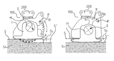
- FIGS. 5 a and 5 b show a side view and a front view of a device according to an embodiment of the present invention, respectively;
- FIGS. 6 a to 6 b show a side view and a front view, respectively, of a device according to an embodiment of the present invention during a processing stage subsequent to that represented in FIGS. 5 a and 5 b;
- FIGS. 7 a to 7 c show respective side views of the device according to an embodiment of the present invention.
- FIGS. 8 and 9 show examples of respective applications and/or uses of the device according to the present invention.
- FIGS. 10 , 11 a and 11 b relate to a perspective view and to two side views, respectively, of a device according to a further embodiment of the present invention
- FIGS. 12 ; 13 a and 13 b relate to a perspective view and to two side views of a device according to a further embodiment of the present invention, respectively.
- the device 100 comprises a main frame T onto which a processing and/or working and/or milling drum 10 is rotatably fixed. From the outer surface of the drum 10 , milling tools 11 extend outwards.
- the milling drum is, in particular, rotatable about a main axis of rotation substantially coincident with its own axis of symmetry. Furthermore, the milling tools 11 can, depending on the needs and/or circumstances, be fixed or interchangeable.
- the main frame T also comprises connecting and/or fixing means 200 which allow the device 100 to be fixed to a main operating machine.
- the main operating machine can be of the type represented in FIGS. 8 and 9 , i.e. a type comprising an articulated connecting main arm which allows the same device to be actuated and moved, in particular, to be positioned in the desired working position. Please refer to the following description for a detailed description of FIGS. 8 and 9 .
- the operating machine can be of the type in which the device is fixed to the front part of the same main operating machine.
- the main frame T is provided with two supporting slides F and L fixed on opposite sides of the main frame. During use, as shown in FIGS.
- the two opposite slides F and L come into contact with the upper surface S of a layer Sr to be processed and/or milled, for example, a layer made of asphalt, concrete or like materials suitable for pedestrians and/or vehicles.
- the two supporting slides F and L each define a contacting portion and/or surface Fa and La, respectively, adapted to be brought into contact with corresponding portions of the upper surface S of layer Sr to be processed. From FIGS.
- the slides F and L define the position of the drum 10 with respect to the same slides and, consequently, the position of drum 10 with respect to the main frame T, as well as the working depth p of the drum 10 .
- the device 10 is provided with means for adjusting or regulating the position of the two slides F and L simultaneously with respect to the main frame T and, thus, with respect to the drum 10 .
- Said means for simultaneously regulating the two slides F and L allow the position of the slides to be adjusted in such a way that the respective contacting portions Fa and La, with the drum 10 (with its main axis of symmetry and/or rotation) in a substantially horizontal position, come into contact with respective portions of the surface S lying at an equal height or level with respect to a reference height or level.
- Said means for simultaneously regulating the position of the two slides F and L are not included in the scope of the present invention and, therefore, will not be clarified in detail for the sake of conciseness.
- the device 100 will, for example, enable the working or processing stage shown in FIGS. 5A and 5B , when the slides F and L are positioned with respect to the main frame T (with respect to the drum 10 ) in such a way that the respective portions Fa and La of the slides F and L come into contact (with the drum 10 in a substantially horizontal position) with corresponding portions of the surface S lying substantially at the same level with respect to a reference height or level.
- a sub-layer of depth p will be removed or milled away from layer Sr, thereby forming a furrow Sc in the layer Sr.
- the device 100 according to the present invention is however also provided with means adapted to enable independent adjustment of the position of the slide L with respect to the main frame T and, thus, with respect to the slide F and to the drum 10 .
- Said further regulating means will thus allow the slide L to be positioned in such a way that, with the drum 10 in a substantially horizontal position, the respective contacting portions Fa and La of the slides F and L may be brought into contact with corresponding portions of the layer Sr (of its upper or exposed surface) lying at different levels with respect to a reference level or height.
- the device according to the embodiment of the present invention represented therein comprises a lever R pivoted on a main frame T.
- the lever R comprises a first end portion H and a second end portion opposite to said first end portion H.
- the first end portion H comprises an engaging or housing seat adapted to be engaged by (to house) a pin E which protrudes outwards from the frame T and extends along a direction substantially parallel to the rotation and/or symmetry main axis of the drum 10 .
- the lever R constitutes a first class lever.
- the first end portion H of the lever R is of a substantially circular or disc-like shape and that the arm of the lever R extends from said substantially circular or disc-shaped portion H.
- the receiving or engaging seat Ra of the pin or fulcrum E is positioned within the circular or disc-shaped portion H, in a position eccentric with respect to the centre of the circular or disc-shaped portion H (see, in particular, FIG. 5A ).
- the lever R can thus be activated as schematically shown in FIG. 5A .
- the end of the lever R opposite to the circular or disc-shaped end portion H can be rotated as shown by the arrow in FIG. 5A .
- the slide L is provided with its own housing, receiving portion or seat Lb (in particular, a through-hole) in which the circular portion H of lever R is housed, one can understand that a rotation of the lever R as indicated by the arrow in FIG. 5A results in a translation (substantially from bottom to top and vice versa) of the slide L.
- the slide L will be translated downwards
- the lever R downwards the slide F will be translated upwards.
- the slide L can be positioned in such a way that the contacting or supporting portion La is positioned at a different level with respect to that at which the contacting or supporting portion Fa of the slide F is positioned.
- This feature of the device according to the embodiment of the present invention represented in the Figures allows for carrying out processing stages, for example, as shown in FIGS. 6A and 6B , in which components or features of the device already described with reference to other Figures are identified with the same reference numbers.
- the device can be positioned with respect to the first furrow Sc in such a way that the contacting portion Fa of the slide F comes into contact with the upper or exposed main surface of the layer Sr, in such a way that the drum 10 is positioned in correspondence to a portion of layer Sr still to be processed and immediately adjacent to the first furrow Sc, as well as in such a way that the slide L is positioned in correspondence to said first furrow Sc, for example, in a position immediately adjacent to the layer Sr still to be removed, and thus, in a position substantially corresponding to the edge of the furrow Sc in contact with the portion of layer Sr still to be processed and/or milled.
- the position of the slide L may be adjusted or regulated by means of the lever R in such a way that its contacting portion La comes into contact with a corresponding portion of the exposed surface S′′ of the furrow Sc. It will thus be possible to maintain a drum 10 in the desired working position (substantially horizontal in FIG. 6 b ).
- the contact or support of the portions Fa and La of the slide F and L with corresponding portions of surface S and surface S′′, respectively, will guarantee the necessary and required stability without risking that the device is laterally slanted and, thus, that the drum 10 may assume undesired positions.
- the lever R is provided with fixing means which allow the lever R to be fixed to the main frame T at predefined positions.
- the lever R comprises a series of through-holes or housing or receiving seats Rb, in which a pin P is engaged or is received.
- the pin P protrudes from the main frame T and extends outwards along a direction substantially parallel to the symmetry and/or rotation main axis of the drum 10 and to the direction along which the pin or fulcrum E extends.
- the lever R On the end portion opposite to the circular or disc-shaped end portion H with respect to the fulcrum E) by rotating it clockwise or counter-clockwise as shown by the arrow in FIG. 5 a and, once the desired position for the slide L has been reached, will proceed to engage the pin P in the engaging or receiving seat Rb which will be positioned substantially in correspondence to the pin P.
- the device 10 may be provided with a pin P which can be translated along a direction substantially parallel to its own symmetry axis and, therefore, adapted to be alternatively extracted from and inserted into the frame T. Otherwise, the lever R can be translated or moved so as to alternatively be pulled further away from or closer to the main frame T.
- FIGS. 7A to 7C further features of the device 100 according to the present invention will be clarified and described. Also, in the case of FIGS. 7A to 7C , those features and/or components of the device according to the present invention which have already been previously described with reference to other Figures, are identified in FIGS. 7A to 7C by the same reference numbers.
- FIGS. 7A to 7C An important feature of the device according to the present invention which can be appreciated from FIGS. 7A to 7C , relates to the fact that the slide L is fixed to the lever R so that the slide L is free to rotate with respect to the lever R. This is achieved, in particular, by rotatably engaging the circular portion H of the lever R in the corresponding receiving seat Lb of the slide L.
- the internal diameter of the seat Lb substantially corresponds to the external diameter of the portion H of the lever R.
- the slide L Since the slide L is free to rotate about the portion H of the lever R, it is allowed to adapt to unevenness and/or irregularities of the surface S′′ with which the contacting portion La of the slide L is in contact during the advancement of the device 100 while processing and/or milling a layer Sr (and thus, substantially from right to left in FIGS. 7 a to 7 c ). Therefore, in a case of the device 100 advancing too quickly, this feature prevents the device 100 from leaning forward, as well as it keeps the drum 10 in the desired position set by adjusting the position of the slide L.
- the slide F can also be fixed to the main frame T so as to be rotatable with respect to said main frame T.
- the lever or connecting element R is fixed to the main frame so as to be free to rotate about the pin E fixedly connected to the main frame T.
- the connecting element R is fixed to the main frame T so as to be free to translate with respect to the main frame T.
- One of such embodiments will be described in some detail in the following with reference to FIGS. 12 , 13 A and 13 B.
- the supporting slide L is rotatably fixed to a first end portion H of the lever or arm or connecting element R.
- the supporting slide L can be fixed to a generic portion of the arm R, not necessarily to one of its end portions. Embodiments in which the supporting slide L is fixed to a portion H of the arm or connecting element R different from an end portion will be described in the following.
- FIGS. 10 , 11 A and 11 B a device according to a further embodiment of the present invention will be described and clarified.
- FIGS. 10 , 11 A and 11 B those features and/or components of the present invention which have been previously described with reference to other Figures, are also identified by the same reference numbers and/or same reference letters.
- the main frame T of the device 10 shown in FIG. 10 comprises the first pin or fulcrum E which extends outward from the frame T in a direction substantially parallel to the main axis of rotation of the drum 10 (not shown in FIG. 10 ).
- a first arm or connecting element R is pivoted on the fulcrum E in such a way that the arm R is rotatable with respect to the fulcrum E in the two clockwise and counter-clockwise directions identified by the double arrow X in FIGS. 10 , 11 A and 11 B.
- the arm R in correspondence to a first end portion, comprises a receiving seat Ea adapted to receive and house the pin E (a receiving seat Ea in which the pin E is engaged).
- the arm R also comprises a connecting pin Rp which extends outwards from the device 100 in a direction substantially parallel to the direction along which the pin or fulcrum E extends.
- a second arm or connecting element Z is arranged between the pin Rp and a further connecting and/or linking pin which extends from the frame T in a substantially parallel direction to the pins E and Rp.
- the length or extension of the second arm Z can be adjusted at will and/or depending on the needs and/or circumstances; for this purpose, in the embodiment shown in FIGS. 10 , 11 A and 11 B, the arm Z comprises a hollow central portion Zc and provided with an internal thread. Two threaded end portions Zf (provided with an external thread) are engaged in the two opposite ends of the arm Z, respectively.
- a rotation of the central portion Zc of the arm Z about its longitudinal axis of symmetry results in a simultaneous translation of the two threaded end portions Zf.
- the two threaded end portions Zf are pushed outwards with respect to the central portion Zc (thereby increasing the length or extension of the arm Z) or inwards with respect to the central portion Zc (and thus, shortening the arm Z).
- the arm R further comprises a cylindrical protrusion H which extends from the arm R towards the main frame T and, thus, from the internal surface of the arm R opposite to the external surface of the arm R from which the pin Rp extends.
- the cylindrical protrusion H of the arm R engages in a receiving seat (a substantially circular through-hole) Lb formed in the slide L.
- the external diameter of the cylindrical protrusion H substantially corresponds to the internal diameter of the engaging and/or receiving seat Lb.
- the arm R rotates alternatively clockwise and counter-clockwise, therefore, the slide L is alternatively translated downwards and upwards (see, in this respect, the double arrow Y in FIG. 11A ).
- the first arm R and the second arm Z connected to each other (by means of the pin Rp) and to the frame T (by means of the pin E and the pin B, respectively) make up an arrangement which may be identified with a second class lever. Indeed, the effort is applied by means of the arm Z, whereas fulcrum coincides with the pin E.
- the load, given by the slide L, is applied to the protrusion H of the arm R, and therefore at a position lying between the effort and the fulcrum.
- the position of the slide L with respect to the slide F and to the frame T (as well as with respect to the drum 10 ) can be adjusted and therefore the contacting portion or surface La of the slide L may come into contact with a corresponding surface portion of the layer Sr to be processed lying at a different level or height from the level or height of the surface portion of the layer Sr which is contacted by the slide F.
- the embodiment of the device 100 shown in FIGS. 10 , 11 A and 11 B thus offers all advantages offered by the previously described and clarified embodiments of the device according to the present invention.
- the slide L is also free to rotate with respect to the arm R, and therefore with respect to the main frame T.
- the slide L is provided with a second receiving seat or eyelet Lc adapted to receive the pin or fulcrum E.
- the semi-circular shape of the eyelet Lc allows, in particular, the slide L to rotate as indicated by the double arrow W in FIGS. 11A and 11B between two opposite end portions defined by the length or extension of the eyelet and in which the fulcrum E comes into contact with the lower and upper end of the eyelet Lc, respectively.
- the slide L can adapt to roughness and/or irregularities of the surface contacted by its contacting portion La.
- the manually actuatable arm Z previously described can be replaced, for example, by a hydraulically and/or mechanically actuatable arm as well as by an arm provided with a spring adapted to automatically define the extension of the arm.
- the arm Z can be implemented according to one among the preferred solutions known to the skilled person.
- FIGS. 12 , 13 A and 13 B a device according to a further embodiment of the present invention will be described and clarified.
- FIGS. 12 , 13 A and 13 B those features and/or parts of the present invention which have been previously described with reference to other Figures, are identified by the same reference numbers and/or by the same reference letters.
- the device 100 according to the embodiment shown in FIGS. 12 , 13 A and 13 B differs from the device according to the embodiment described above and shown in FIGS. 10 , 11 A and 11 B, firstly in that in the embodiment shown in FIGS. 12 , 13 A and 13 B the slide L is positioned at an intermediate position between the arm Z and the connecting or linking element R. In other words, the connecting and/or linking element R is positioned between the main frame T and the slide L.
- the frame T of the device 100 shown in FIG. 12 comprises two parallel guides Ga and Gb (with an L- or T-shaped cross-section) which engage in two corresponding receiving seats Rb formed in the connecting element R.
- the guides Ga and Gb allow the element R to be translated along a direction substantially parallel to that along which the two guides Ga and Gb extend (from top to bottom and from bottom to top in FIGS. 12 , 13 A and 13 B), as well as to maintain a predefined distance from the frame T.
- the arm or element R also comprises a connecting pin Rp which extends outwards from the device 100 in a direction substantially parallel to the longitudinal axis of symmetry and/or of rotation of the drum 10 (not shown in FIGS.
- the pin Rp extends from a cylindrical portion H which, in turn, extends from the element R outwards with respect to the device 100 .
- a second arm or connecting element Z is also arranged between the pin Rp and a further connecting and/or linking pin which extends from the frame T in a direction substantially parallel to the pin Rp.
- the length or extension of the second arm Z can be adjusted at will and/or depending on the needs and/or circumstances, as in the case of the embodiment previously described; for this purpose, the arm Z still comprises a central hollow portion Ec provided with an internal thread, in the opposite ends of which, two threaded end portions Zf (provided with an external thread) are engaged.
- a rotation of the central portion Zc of the arm Z about its longitudinal axis of symmetry results in a simultaneous translation of the two threaded end portions Zf.
- the two threaded end portions Zf are pushed outwards with respect to the central portion Zc (thus increasing the length or extension of the arm Z) or inwards with respect to the central portion Zc (and, thus, shortening the arm Z).
- a downwards and upwards translation of the element R is obtained, respectively.
- the cylindrical protrusion H of the arm R is engaged in a receiving seat Lb (a substantially circular through-hole) formed in the slide L.
- the external diameter of the cylindrical protrusion H substantially corresponds to the internal diameter of the engaging and/or receiving seat Lb. Therefore, from the previous description, one can understand that, by alternatively lengthening and shortening the arm Z, the arm R is respectively translated downwards and upwards, so that the slide L also follows the translation of the element or arm R and is therefore translated respectively and alternatively downwards and upwards (see in this respect, the double arrow Y in FIG. 13A ).
- the position of the slide L with respect to the slide F and to the frame T (as well as with respect to the drum 10 ) can thus be adjusted, so that the contacting portion or surface La of the slide L can come into contact with a corresponding surface portion of the layer Sr to be processed lying at a different level or height from the level or height of the surface portion of the layer Sr which is contacted by the slide F.
- the slide L is also free to rotate with respect to the connecting and/or linking element R, and therefore with respect to the main frame T.
- the slide L is fixed to the protrusion H of the connecting element R so as to be free to rotate in the directions indicated by the double arrow drawn on the supporting element L in FIG. 12 .
- the slide L can adapt to roughness, unevenness and/or irregularities of the surface contacted by its contacting portion La.
- FIGS. 12 , 13 A and 13 B thus offers all advantages offered by the previously described and clarified embodiments of the device according to the present invention.
- the manually actuatable arm Z previously described can be replaced, for example, by a hydraulically and/or mechanically actuatable arm, as well as by an arm provided with a spring adapted to automatically define the extension of the arm.
- the arm Z can be implemented according to one of the preferred embodiments known to the skilled person.
- FIGS. 8 and 9 an example of an application of the device 100 according to the present invention is represented.
- the device 100 is applied to the end of an articulated main arm 300 of a main operating machine M.
- the device 100 can be mounted to the arm 300 by means of fixing means 200 previously described and with which the device 100 is provided. Moving the device 100 is thus substantially achieved by means of the arm 300 , which can, for example, be hydraulically actuatable.
- the rotation of the working drum 10 of the device 100 can also be induced by a mechanism of a hydraulic type, in particular by means of a hydraulic power source actuated by the operating machine M, the hydraulic power being thus transmitted to the device 100 by means of hydraulic conduits which extend along the arm 300 .
- Advancement of the device 100 is obtained by actuating the arm 300 so as to reduce or increase the distance between the device 100 and the operating machine M depending on the orientation chosen for the device (depending on whether the device is oriented with the drum facing the machine M or vice versa). Alternatively, advancement of the device 100 can be obtained by keeping the arm 100 fixed and moving the operating machine M.
- the present invention enables achieving the given goals and overcomes, or at least, minimizes the drawbacks typical with systems or devices known from the state of the art.
- the device according to the present invention enables an independent regulation of the position of the two supporting slides F and L with respect to the main frame T and/or to the working drum 10 .
- the solution according to the present invention allows a device for processing, in particular, for milling solid layers, such as for example, surfaces made of asphalt and/or concrete to be steadily positioned in any conditions as well as to form in said layers adjacent and contiguous furrows without leaving any layer portions still to be removed and/or processed between two adjacent and/or subsequent furrows.
- all working capabilities of the device are thus exploited and processing stages, which in the case of a device of known type are necessary for milling and/or processing layer portions between two adjacent furrows, can be avoided.
- the device according to the present invention can adapt to roughness and/or unevenness of the layer to be processed, thereby maintaining the milling drum in the desired working position.
- the present invention is not limited to the embodiments previously described and shown in the Figures. Conversely, all those modifications and variations of the embodiments described and shown which are clear to an expert in the field, are a part of the scope of the present invention.
- the present invention is not limited to manual means for regulating the position of at least one supporting slide but also comprises mechanical and/or hydraulic means (by means of which the slide is hydraulically moved). The scope and the range of the present invention are thus defined by the claims.
Landscapes
- Engineering & Computer Science (AREA)
- Mining & Mineral Resources (AREA)
- Architecture (AREA)
- Civil Engineering (AREA)
- Structural Engineering (AREA)
- Mechanical Engineering (AREA)
- Soil Working Implements (AREA)
- Shovels (AREA)
- Harvester Elements (AREA)
Applications Claiming Priority (4)
| Application Number | Priority Date | Filing Date | Title |
|---|---|---|---|
| IT000097A ITBO20110097A1 (it) | 2011-03-01 | 2011-03-01 | Apparecchiatura per la lavorazione e in particolare per la demolizione e/o fresatura di superfici orizzontali , verticali o inclinate con scavo senza gradini |
| ITBO2011A000097 | 2011-03-01 | ||
| ITB02011A0097 | 2011-03-01 | ||
| PCT/EP2012/000901 WO2012116821A1 (en) | 2011-03-01 | 2012-03-01 | Device for processing and in particular for demolishing and/or milling horizontal, vertical, or inclined surfaces with step less cuts |
Publications (2)
| Publication Number | Publication Date |
|---|---|
| US20140042794A1 US20140042794A1 (en) | 2014-02-13 |
| US9127417B2 true US9127417B2 (en) | 2015-09-08 |
Family
ID=43976825
Family Applications (1)
| Application Number | Title | Priority Date | Filing Date |
|---|---|---|---|
| US14/001,760 Active US9127417B2 (en) | 2011-03-01 | 2012-03-01 | Device for processing and in particular for demolishing and/or milling horizontal, vertical, or inclined surfaces with step less cuts |
Country Status (6)
| Country | Link |
|---|---|
| US (1) | US9127417B2 (de) |
| EP (1) | EP2495367B1 (de) |
| BR (1) | BR112013021978A2 (de) |
| IT (1) | ITBO20110097A1 (de) |
| RU (1) | RU2621330C2 (de) |
| WO (1) | WO2012116821A1 (de) |
Cited By (4)
| Publication number | Priority date | Publication date | Assignee | Title |
|---|---|---|---|---|
| US10385523B2 (en) | 2017-12-20 | 2019-08-20 | Caterpillar Paving Products Inc. | Moldboard retention system for a milling machine |
| US12037755B2 (en) | 2022-08-18 | 2024-07-16 | Wirtgen Gmbh | Dual drive milling attachment |
| US12071733B2 (en) | 2022-08-18 | 2024-08-27 | Wirtgen Gmbh | Milling attachment with adjustable cover |
| US12497741B2 (en) | 2022-02-09 | 2025-12-16 | Wirtgen Gmbh | Mounted earth removal device having a split side plate |
Families Citing this family (9)
| Publication number | Priority date | Publication date | Assignee | Title |
|---|---|---|---|---|
| DE202012104064U1 (de) | 2012-10-23 | 2013-03-06 | Stehr Baumaschinen Gmbh | Fahrbares und/oder an ein Trägerfahrzeug anbaubares Bodenbearbeitungsgerät |
| GB2512945B (en) * | 2013-04-13 | 2015-08-26 | Auger Torque Europ Ltd | Ground planer |
| US20170101746A1 (en) * | 2015-10-09 | 2017-04-13 | The Charles Machine Works, Inc. | Trenching Assembly |
| IT201600119002A1 (it) * | 2016-11-24 | 2018-05-24 | Simex Eng S R L | Apparecchiatura per la lavorazione di superfici, in particolare di superfici solide, in particolare per la realizzazione di bande sonore |
| IT201800006830A1 (it) * | 2018-06-29 | 2019-12-29 | Apparecchiatura e assieme di scavo | |
| CN111005281B (zh) * | 2019-11-25 | 2022-05-17 | 济宁市公路工程总公司 | 公路路面施工设备及利用其实现的公路路面施工方法 |
| IT202000025711A1 (it) * | 2020-10-29 | 2022-04-29 | Simex S R L | Assieme di fresa per fresare un manto stradale o suolo |
| CZ310354B6 (cs) * | 2022-02-09 | 2025-04-02 | Exact Control System a.s. | Způsob frézování povrchu dopravní plochy v alespoň dvou vrstvách |
| CN117286767B (zh) * | 2023-11-22 | 2024-01-26 | 徐州屈恩工程机具制造有限公司 | 一种道路标线铣刨器 |
Citations (6)
| Publication number | Priority date | Publication date | Assignee | Title |
|---|---|---|---|---|
| US4803789A (en) * | 1986-02-06 | 1989-02-14 | Alfred Hackmack | Milling device |
| DE9407487U1 (de) | 1994-05-05 | 1994-07-07 | Humme, Thomas, 52385 Nideggen | Fräsmaschine |
| US5381616A (en) * | 1990-03-27 | 1995-01-17 | R. & R. Trench Equipment Limited | Rotary rockwheel assemblies |
| US6116699A (en) * | 1998-07-29 | 2000-09-12 | Clark Equipment Company | Planer with edge planing capability |
| US20090232598A1 (en) | 2008-03-11 | 2009-09-17 | Gary Cochran | Adjustable planer system |
| DE202010010857U1 (de) | 2010-07-30 | 2010-10-21 | MTS Gesellschaft für Maschinentechnik und Sonderbauten mbH | Fräseinrichtung |
Family Cites Families (5)
| Publication number | Priority date | Publication date | Assignee | Title |
|---|---|---|---|---|
| SU1399389A1 (ru) * | 1985-07-18 | 1988-05-30 | Московский Автомобильно-Дорожный Институт | Устройство дл фрезеровани дорожных покрытий |
| SU1395727A1 (ru) * | 1986-05-06 | 1988-05-15 | Проектно-конструкторское бюро Академии коммунального хозяйства им.К.Д.Памфилова | Устройство дл фрезеровани дорожных покрытий |
| SU1507917A1 (ru) * | 1987-12-29 | 1989-09-15 | Всесоюзный Научно-Исследовательский Институт Землеройного Машиностроения | Планировщик |
| US7117864B2 (en) * | 2004-06-30 | 2006-10-10 | Diamond Products, Limited | Mobile road or floor saw |
| RU2297124C2 (ru) * | 2004-07-30 | 2007-04-20 | Олег Александрович Иванов | Культиватор для удаления сорняков с огородной гряды |
-
2011
- 2011-03-01 IT IT000097A patent/ITBO20110097A1/it unknown
-
2012
- 2012-03-01 US US14/001,760 patent/US9127417B2/en active Active
- 2012-03-01 BR BR112013021978A patent/BR112013021978A2/pt not_active IP Right Cessation
- 2012-03-01 RU RU2013142689A patent/RU2621330C2/ru active
- 2012-03-01 EP EP12157732.4A patent/EP2495367B1/de active Active
- 2012-03-01 WO PCT/EP2012/000901 patent/WO2012116821A1/en not_active Ceased
Patent Citations (6)
| Publication number | Priority date | Publication date | Assignee | Title |
|---|---|---|---|---|
| US4803789A (en) * | 1986-02-06 | 1989-02-14 | Alfred Hackmack | Milling device |
| US5381616A (en) * | 1990-03-27 | 1995-01-17 | R. & R. Trench Equipment Limited | Rotary rockwheel assemblies |
| DE9407487U1 (de) | 1994-05-05 | 1994-07-07 | Humme, Thomas, 52385 Nideggen | Fräsmaschine |
| US6116699A (en) * | 1998-07-29 | 2000-09-12 | Clark Equipment Company | Planer with edge planing capability |
| US20090232598A1 (en) | 2008-03-11 | 2009-09-17 | Gary Cochran | Adjustable planer system |
| DE202010010857U1 (de) | 2010-07-30 | 2010-10-21 | MTS Gesellschaft für Maschinentechnik und Sonderbauten mbH | Fräseinrichtung |
Cited By (4)
| Publication number | Priority date | Publication date | Assignee | Title |
|---|---|---|---|---|
| US10385523B2 (en) | 2017-12-20 | 2019-08-20 | Caterpillar Paving Products Inc. | Moldboard retention system for a milling machine |
| US12497741B2 (en) | 2022-02-09 | 2025-12-16 | Wirtgen Gmbh | Mounted earth removal device having a split side plate |
| US12037755B2 (en) | 2022-08-18 | 2024-07-16 | Wirtgen Gmbh | Dual drive milling attachment |
| US12071733B2 (en) | 2022-08-18 | 2024-08-27 | Wirtgen Gmbh | Milling attachment with adjustable cover |
Also Published As
| Publication number | Publication date |
|---|---|
| RU2621330C2 (ru) | 2017-06-02 |
| EP2495367A1 (de) | 2012-09-05 |
| RU2013142689A (ru) | 2015-04-10 |
| EP2495367B1 (de) | 2015-06-03 |
| ITBO20110097A1 (it) | 2012-09-02 |
| WO2012116821A1 (en) | 2012-09-07 |
| US20140042794A1 (en) | 2014-02-13 |
| BR112013021978A2 (pt) | 2018-06-12 |
Similar Documents
| Publication | Publication Date | Title |
|---|---|---|
| US9127417B2 (en) | Device for processing and in particular for demolishing and/or milling horizontal, vertical, or inclined surfaces with step less cuts | |
| WO2014207583A1 (en) | Mounting mechanism of a winning and loading machine for thin seams | |
| US10508411B2 (en) | Grading tools for work machines and operation thereof | |
| GB2473683A (en) | Method and apparatus for driving a pile into a substrate | |
| US20100058910A1 (en) | Slide circular saw | |
| AU2014262089B2 (en) | Crop lifter with angle and finger adjustment | |
| RU2016133450A (ru) | Траншеекопатель с выравнивающими средствами | |
| EP2823701A1 (de) | Säelement mit Griff zum Einstellen des Senkdrucks, und entsprechender Griff | |
| US1547096A (en) | Grooving machine | |
| US6755481B2 (en) | Cutting blade and method for cutting pavement in a circle | |
| FR3038922A1 (fr) | Engin de travail motorise et mobile | |
| US2614805A (en) | Posthole digger | |
| KR101450299B1 (ko) | 정지작업용 가변 휴립장치 | |
| JP6645344B2 (ja) | 移植機 | |
| US1069340A (en) | Means for tilting the earth-turning elements of wheeled plows. | |
| WO2016102646A1 (en) | Excavating equipment for excavating surfaces, in particular solid surfaces, and operating machine equipped with said excavating equipment | |
| FR3077346A3 (fr) | Taquet a excentrique | |
| RU2663919C1 (ru) | Центробежный рабочий орган для рассева сыпучих материалов | |
| CZ299640B6 (cs) | Zarízení pro regulaci polohy zavlacovace | |
| CN220693710U (zh) | 一种播种机开沟器 | |
| FR2988261A1 (fr) | Dispositif de travail du sol en preparation des semis. | |
| DE202014005416U1 (de) | Rasenmäher | |
| US316301A (en) | Shingle-sawing machine | |
| JP2022099080A (ja) | 畦塗り機 | |
| KR102347523B1 (ko) | 고구마 종자 파종용 평탄 작업장치 |
Legal Events
| Date | Code | Title | Description |
|---|---|---|---|
| AS | Assignment |
Owner name: SIMEX S.R.L., ITALY Free format text: ASSIGNMENT OF ASSIGNORS INTEREST;ASSIGNOR:RISI, MIRCO;REEL/FRAME:031527/0788 Effective date: 20131024 |
|
| STCF | Information on status: patent grant |
Free format text: PATENTED CASE |
|
| MAFP | Maintenance fee payment |
Free format text: PAYMENT OF MAINTENANCE FEE, 4TH YEAR, LARGE ENTITY (ORIGINAL EVENT CODE: M1551); ENTITY STATUS OF PATENT OWNER: LARGE ENTITY Year of fee payment: 4 |
|
| FEPP | Fee payment procedure |
Free format text: ENTITY STATUS SET TO SMALL (ORIGINAL EVENT CODE: SMAL); ENTITY STATUS OF PATENT OWNER: SMALL ENTITY |
|
| MAFP | Maintenance fee payment |
Free format text: PAYMENT OF MAINTENANCE FEE, 8TH YR, SMALL ENTITY (ORIGINAL EVENT CODE: M2552); ENTITY STATUS OF PATENT OWNER: SMALL ENTITY Year of fee payment: 8 |