US9128163B2 - Voltage measuring apparatus for plural battery - Google Patents
Voltage measuring apparatus for plural battery Download PDFInfo
- Publication number
- US9128163B2 US9128163B2 US13/878,577 US201113878577A US9128163B2 US 9128163 B2 US9128163 B2 US 9128163B2 US 201113878577 A US201113878577 A US 201113878577A US 9128163 B2 US9128163 B2 US 9128163B2
- Authority
- US
- United States
- Prior art keywords
- voltage
- charging state
- measuring apparatus
- reference voltage
- state monitoring
- Prior art date
- Legal status (The legal status is an assumption and is not a legal conclusion. Google has not performed a legal analysis and makes no representation as to the accuracy of the status listed.)
- Active, expires
Links
Images



Classifications
-
- G01R31/362—
-
- G—PHYSICS
- G01—MEASURING; TESTING
- G01R—MEASURING ELECTRIC VARIABLES; MEASURING MAGNETIC VARIABLES
- G01R31/00—Arrangements for testing electric properties; Arrangements for locating electric faults; Arrangements for electrical testing characterised by what is being tested not provided for elsewhere
- G01R31/36—Arrangements for testing, measuring or monitoring the electrical condition of accumulators or electric batteries, e.g. capacity or state of charge [SoC]
- G01R31/382—Arrangements for monitoring battery or accumulator variables, e.g. SoC
- G01R31/3835—Arrangements for monitoring battery or accumulator variables, e.g. SoC involving only voltage measurements
-
- G01R31/3658—
-
- G—PHYSICS
- G01—MEASURING; TESTING
- G01R—MEASURING ELECTRIC VARIABLES; MEASURING MAGNETIC VARIABLES
- G01R31/00—Arrangements for testing electric properties; Arrangements for locating electric faults; Arrangements for electrical testing characterised by what is being tested not provided for elsewhere
- G01R31/36—Arrangements for testing, measuring or monitoring the electrical condition of accumulators or electric batteries, e.g. capacity or state of charge [SoC]
- G01R31/374—Arrangements for testing, measuring or monitoring the electrical condition of accumulators or electric batteries, e.g. capacity or state of charge [SoC] with means for correcting the measurement for temperature or ageing
-
- G—PHYSICS
- G01—MEASURING; TESTING
- G01R—MEASURING ELECTRIC VARIABLES; MEASURING MAGNETIC VARIABLES
- G01R31/00—Arrangements for testing electric properties; Arrangements for locating electric faults; Arrangements for electrical testing characterised by what is being tested not provided for elsewhere
- G01R31/36—Arrangements for testing, measuring or monitoring the electrical condition of accumulators or electric batteries, e.g. capacity or state of charge [SoC]
- G01R31/396—Acquisition or processing of data for testing or for monitoring individual cells or groups of cells within a battery
-
- H—ELECTRICITY
- H01—ELECTRIC ELEMENTS
- H01M—PROCESSES OR MEANS, e.g. BATTERIES, FOR THE DIRECT CONVERSION OF CHEMICAL ENERGY INTO ELECTRICAL ENERGY
- H01M10/00—Secondary cells; Manufacture thereof
- H01M10/42—Methods or arrangements for servicing or maintenance of secondary cells or secondary half-cells
- H01M10/48—Accumulators combined with arrangements for measuring, testing or indicating the condition of cells, e.g. the level or density of the electrolyte
- H01M10/482—Accumulators combined with arrangements for measuring, testing or indicating the condition of cells, e.g. the level or density of the electrolyte for several batteries or cells simultaneously or sequentially
-
- G—PHYSICS
- G01—MEASURING; TESTING
- G01R—MEASURING ELECTRIC VARIABLES; MEASURING MAGNETIC VARIABLES
- G01R19/00—Arrangements for measuring currents or voltages or for indicating presence or sign thereof
- G01R19/165—Indicating that current or voltage is either above or below a predetermined value or within or outside a predetermined range of values
- G01R19/16533—Indicating that current or voltage is either above or below a predetermined value or within or outside a predetermined range of values characterised by the application
- G01R19/16538—Indicating that current or voltage is either above or below a predetermined value or within or outside a predetermined range of values characterised by the application in AC or DC supplies
- G01R19/16542—Indicating that current or voltage is either above or below a predetermined value or within or outside a predetermined range of values characterised by the application in AC or DC supplies for batteries
-
- G—PHYSICS
- G01—MEASURING; TESTING
- G01R—MEASURING ELECTRIC VARIABLES; MEASURING MAGNETIC VARIABLES
- G01R35/00—Testing or calibrating of apparatus covered by the other groups of this subclass
-
- Y—GENERAL TAGGING OF NEW TECHNOLOGICAL DEVELOPMENTS; GENERAL TAGGING OF CROSS-SECTIONAL TECHNOLOGIES SPANNING OVER SEVERAL SECTIONS OF THE IPC; TECHNICAL SUBJECTS COVERED BY FORMER USPC CROSS-REFERENCE ART COLLECTIONS [XRACs] AND DIGESTS
- Y02—TECHNOLOGIES OR APPLICATIONS FOR MITIGATION OR ADAPTATION AGAINST CLIMATE CHANGE
- Y02E—REDUCTION OF GREENHOUSE GAS [GHG] EMISSIONS, RELATED TO ENERGY GENERATION, TRANSMISSION OR DISTRIBUTION
- Y02E60/00—Enabling technologies; Technologies with a potential or indirect contribution to GHG emissions mitigation
- Y02E60/10—Energy storage using batteries
Definitions
- the present invention relates to a voltage measuring apparatus for a plural battery, for detecting an output voltage of the plural battery that connects a plurality of unit cells in series to output a required voltage, and particularly, to a technique of detecting a voltage measurement error and improving detection accuracy.
- an electric car, a hybrid vehicle, or the like has a high-voltage battery as a power source for driving a motor.
- a high-voltage battery connects a plurality of unit cells of a secondary battery (rechargeable battery) such as a nickel-hydrogen battery and a lithium battery in series to provide a high voltage.
- a secondary battery rechargeable battery
- each unit cell In the secondary battery, each unit cell is charged with the same power and is discharged at the same power. Accordingly, if the individual unit cells differently deteriorate, the secondary battery will easily get an overcharge or overdischarge state. To prevent the overcharge or overdischarge state of the secondary battery, the charging state of each unit cell must be checked.
- a plurality of (for example, 55) unit cells are divided into, for example, five blocks (namely, 11 unit cells per block) and a cell voltage of each unit cell contained in each block is measured in real time with a voltage detecting IC provided for each block, to monitor if the voltage is abnormal.
- the voltage detecting IC measures voltages of the unit cells (for example, 11 pieces) in the block, converts a detected analog voltage signal into a digital signal with an A/D converter contained in the voltage detecting IC, and transmits the digital signal to a main microcomputer.
- Each voltage detecting IC may involve an error in the accuracy of unit cell voltage measurement.
- the error if exists, must be detected and calibrated.
- This related art computes an average of unit cell voltages of each block (each voltage detecting IC) and sets the average as a representative value of the block. According to the representative value, the related art detects a detection error in each unit cell voltage, and if the error is large, corrects the error.
- the related art mentioned above employs the method of finding a voltage measurement error according to a reference voltage, i.e., an average of unit cell voltages of each block, and therefore, involves a problem that, if the cell voltages of the unit cells contained in the block vary as a whole, the reference voltage itself becomes unreliable for conducting accurate correction.
- a reference voltage i.e., an average of unit cell voltages of each block
- the present invention provides a voltage measuring apparatus for a plural battery, capable of highly accurately calibrating the voltage detection accuracy of each voltage detecting unit.
- a voltage measuring apparatus for a plural battery that connects a plurality of cells in series to output a required voltage.
- the apparatus measures an output voltage of each of the cells and includes a voltage detecting part provided for each of a plurality of blocks into which the plurality of cells are divided, to detect each cell voltage in the block and a charging state monitoring part to monitor a charging state of each cell voltage according to the cell voltages detected by the voltage detecting parts.
- Each of the voltage detecting units includes a communication part to transmit and receive data to and from the charging state monitoring part, a reference voltage generating part having a series-connected circuit of a resistor and at least one diode to output a reference voltage that is generated across the diode when a voltage is applied across the series-connected circuit, and an A/D conversion part to digitize an output voltage of each cell and the reference voltage.
- the communication part transmits the digitized voltage signals to the charging state monitoring part.
- the charging state monitoring part includes a theoretical value generating part to generate, according to an ambient temperature, a theoretical voltage generating across the diode and an error detecting part to compare the digitized voltage signal of the reference voltage transmitted from the voltage detecting part with the theoretical value, and according to a result of the comparison, detect an error in the voltage signals digitized by the A/D conversion part.
- FIG. 1 is a block diagram illustrating a configuration of a voltage measuring apparatus for a plural battery according to an embodiment of the present invention.
- FIG. 2 is a block diagram illustrating a detailed configuration of a voltage detecting IC arranged in the voltage measuring apparatus for a plural battery according to the embodiment of the present invention.
- FIG. 3 is a circuit diagram illustrating a reference voltage generator arranged in the voltage measuring apparatus for a plural battery according to the embodiment of the present invention.
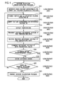
- FIG. 4 is a flowchart illustrating a processing operation of the voltage measuring apparatus for a plural battery according to the embodiment of the present invention.
- FIG. 5 is a flowchart illustrating a processing operation of the voltage measuring apparatus for a plural battery according to the embodiment of the present invention.
- FIG. 6 is a circuit diagram illustrating a reference voltage generator arranged in the voltage measuring apparatus for a plural battery according to the embodiment of the present invention.
- FIG. 1 is a block diagram illustrating a voltage measuring apparatus 10 according to the embodiment of the present invention and a secondary battery (plural battery of an assembled battery) 13 including a plurality of unit cells BT 1 to BT 55 and
- FIG. 2 is a block diagram illustrating a detailed configuration of a voltage detecting IC ( 21 - 1 ).
- the secondary battery 13 adopted by this embodiment is used as, for example, a high-voltage battery to drive a motor of an electric car, a hybrid vehicle, or the like.
- the voltage measuring apparatus 10 is separated by an insulating interface 32 into a high-voltage-side apparatus 11 and a low-voltage-side apparatus 12 .
- the high-voltage-side apparatus 11 includes five voltage detecting ICs, i.e., the first voltage detecting IC ( 21 - 1 ) to the fifth voltage detecting IC ( 21 - 5 ).
- the first voltage detecting IC ( 21 - 1 ) measures a cell voltage of each of 11 unit cells BT 1 to BT 11 that are grouped into a first block ( 61 - 1 ).
- the second voltage detecting IC ( 21 - 2 ) measures a cell voltage of each of 11 unit cells BT 12 to BT 22 that are grouped into a second block ( 61 - 2 ).
- the third voltage detecting IC ( 21 - 3 ) measures a cell voltage of each of 11 unit cells BT 23 to BT 33 that are grouped into a third block ( 61 - 3 ).
- the fourth voltage detecting IC ( 21 - 4 ) measures a cell voltage of each of 11 unit cells BT 34 to BT 44 that are grouped into a fourth block ( 61 - 4 ).
- the fifth voltage detecting IC ( 21 - 5 ) measures a cell voltage of each of 11 unit cells BT 45 to BT 55 that are grouped into a fifth block ( 61 - 5 ).
- Each of the voltage detecting ICs ( 21 - 1 ) to ( 21 - 5 ) has an A/D converter (A/D conversion part) 26 (refer to FIG. 2 ) that uses an A/D converting voltage Vf 0 provided by a corresponding one of reference voltage sources ( 71 - 1 ) to ( 71 - 5 ) to convert cell voltages (an analog voltage signal) of a corresponding block (one of the first to fifth blocks) into a digital voltage signal.
- A/D converter A/D conversion part
- the voltage detecting ICs ( 21 - 1 ) to ( 21 - 5 ) are connected to thermo sensors (temperature detectors) ( 34 - 1 ) to ( 34 - 5 ), respectively, to detect an ambient temperature.
- the voltage detecting ICs ( 21 - 1 ) to ( 21 - 5 ) will be explained.
- the second to fifth voltage detecting ICs ( 21 - 2 ) to ( 21 - 5 ) have the same configuration as the first voltage detecting IC ( 21 - 1 ), and therefore, the first voltage detecting IC ( 21 - 1 ) will be explained as an example.
- the first voltage detecting IC ( 21 - 1 ) includes a power source circuit 23 that receives power from the unit cells and generates a predetermined voltage, an input part of cell voltage 22 that is connected to the unit cells BT 1 to BT 11 of the first block ( 61 - 1 ) to detect output power of these unit cells, a multiplexer 25 that converts voltage signals of the unit cells outputted from the input part of cell voltage 22 into a time-series signal, and a reference voltage generator 24 that generates a reference voltage.
- the A/D converter 26 that converts the voltage signal of the unit cells BT 1 to BT 11 outputted from the multiplexer 25 and the voltage signal outputted from the reference voltage generator 24 each into a digital signal and a switch SW 1 that selects one of the output signals of the multiplexer 25 and reference voltage generator 24 and supplies the selected one to the A/D converter 26 .
- the A/D converter 26 digitizes the analog voltage signal according to the A/D conversion voltage Vf 0 outputted from the reference power source ( 71 - 1 ).
- the first voltage detecting IC ( 21 - 1 ) also includes a control part 27 and two communication I/Fs (communication part) 35 a and 35 b .
- the control part 27 carries out a process of transmitting the digital voltage signal from the A/D converter 26 through the communication I/Fs 35 a and 35 b to a main microcomputer 33 illustrated in FIG. 1 .
- the switch SW 1 operates under the control of the control part 27 and is connected to the multiplexer 25 in a normal state and to the reference voltage generator 24 in a case of calibrating the accuracy of voltage detection such as initializing the apparatus for shipment.
- the second to fifth voltage detecting ICs ( 21 - 2 ) to ( 21 - 5 ) are connected through a communication line 31 to the first voltage detecting IC ( 21 - 1 ) and the voltage detecting IC ( 21 - 1 ) is connected through the insulating interface 32 to the main microcomputer 33 arranged in the low-voltage-side apparatus 12 .
- the main microcomputer 33 and voltage detecting ICs ( 21 - 1 ) to ( 21 - 5 ) are connected through the insulating interface 32 to each other to realize daisy-chain communication.
- the main microcomputer 33 is connected through the insulating I/F 32 to the first voltage detecting IC ( 21 - 1 ), to issue a voltage detecting instruction and voltage calibrating process instruction to the voltage detecting ICs ( 21 - 1 ) to ( 21 - 5 ), receive voltage signals from the voltage detecting ICs ( 21 - 1 ) to ( 21 - 5 ), read the voltages of the unit cells BT 1 to BT 55 , and transmit them to a higher system (not illustrated).
- the main microcomputer 33 functions as a charging state monitoring part to monitor a charging state of each cell voltage according to the cell voltages detected by the voltage detecting ICs ( 21 - 1 ) to ( 21 - 5 ).
- the main microcomputer 33 is also connected to a memory 36 .
- FIG. 3 is a circuit diagram illustrating a detailed configuration of the reference voltage generator 24 .
- the reference voltage generator 24 has a series-connected circuit including a resistor (resistance body) Rref 1 and a diode D 1 .
- One end of the resistor Rref 1 is connected to a supply point of a power source Vcc 1 and one end of the diode D 1 is grounded.
- a connection point of the resistor Rref 1 and diode D 1 is connected to a buffer amplifier 51 . Accordingly, a voltage generated at an output terminal of the buffer amplifier 51 is a voltage obtained by stabilizing a voltage across the diode D 1 . This voltage serves as a reference voltage Vf.
- the memory 36 connected to the main microcomputer 33 stores theoretical value data of the reference voltage Vf related to ambient temperatures. Namely, a voltage to be generated across the diode D 1 illustrated in FIG. 3 is provided as a function of an ambient temperature. If an ambient temperature is determined, a voltage to be generated across the diode D 1 is uniquely determined, and therefore, the memory 36 stores a temperature-theoretical value correspondence table indicating correspondence between ambient temperatures and theoretical values of the reference voltage Vf. Namely, the memory 36 functions as a theoretical value generating part that provides a theoretical value of the voltage generated across the diode D 1 with respect to an ambient temperature.
- the main microcomputer 33 compares an actually measured value of the reference voltage Vf detected by each of the voltage detecting ICs ( 21 - 1 ) to ( 21 - 5 ) with the theoretical value and finds an error in the voltage signal digitized by the A/D converter 26 .
- the main microcomputer 33 functions as an error detecting means that compares a digitized voltage signal of the reference voltage with a theoretical value, and according to a result of the comparison, detects an error in the voltage signal digitized by the A/D conversion means.
- the switch SW 1 in each of the voltage detecting ICs ( 21 - 1 ) to ( 21 - 5 ) illustrated in FIG. 2 is connected to the multiplexer 25 . Accordingly, cell voltages of the unit cells BT- 1 to BT- 11 connected to the first voltage detecting IC ( 21 - 1 ) are converted by the multiplexer 25 into a serial signal, which is digitized by the A/D converter 26 . The digitized voltage signal is transmitted through the communication I/Fs 35 a and 35 b to the main microcomputer 33 . The main microcomputer 33 , therefore, obtains the cell voltages of the unit cells BT- 1 to BT- 55 and monitors whether or not the unit cells BT- 1 to BT- 55 cause overdischarge or overcharge.
- the main microcomputer 33 transmits a signal of instructing a voltage calibration process to the voltage detecting ICs ( 21 - 1 ) to ( 21 - 5 ) (step S 11 ).
- the control part 27 of the first voltage detecting IC changes the switch SW 1 to the reference voltage generator 24 (step S 12 ).
- a reference voltage outputted from the reference voltage generator 24 i.e., the reference voltage Vf outputted from the buffer amplifier 51 of the circuit illustrated in FIG. 3 is outputted to the A/D converter 26 .
- the A/D converter 26 digitizes the reference voltage Vf outputted from the reference voltage generator 24 (step S 13 ).
- the thermo sensor ( 34 - 1 ) detects an ambient temperature of the first voltage detecting IC ( 21 - 1 ) (step S 14 ).
- the communication I/Fs 35 a and 35 b transmit, through the insulating I/F 32 , the digitized reference voltage Vf and the temperature data detected by the thermo sensor ( 34 - 1 ) to the main microcomputer 33 in the low-voltage-side apparatus 12 (step S 15 ).
- the main microcomputer 33 receives the reference voltage Vf and temperature data transmitted from the first voltage detecting IC ( 21 - 1 ).
- the main microcomputer 33 refers to the temperature-theoretical value correspondence table stored in the memory 36 and finds a theoretical value for the reference voltage Vf according to the temperature data. Namely, a voltage to be generated across the diode D 1 illustrated in FIG. 3 is a function of a temperature, and the voltage is determined as the temperature is determined. This voltage is provided as the theoretical value. This theoretical value is compared with the measured reference voltage Vf transmitted from the voltage detecting IC ( 21 - 1 ) (step S 17 ).
- step S 18 an error between the theoretical value and the measured value is computed and it is determined whether or not the error is within a predetermined range (step S 18 ). If it is determined that the error is not within the predetermined range (the error is large) (NO in step S 18 ), the error is stored in the memory 36 (step S 19 ). If the error is within the predetermined range (the error is small) (YES in step S 18 ), the detected error is not stored.
- the main microcomputer 33 sequentially processes the voltage detecting ICs ( 21 - 2 ) to ( 21 - 5 ) (step S 20 ), and if all of the voltage detecting ICs ( 21 - 1 ) to ( 21 - 5 ) are processed, carries out a calibration process of the thermo sensors ( 34 - 1 ) to ( 34 - 5 ) (step S 21 ). The details of the temperature calibration process will be explained later.
- the detected cell voltages are corrected according to the error between the theoretical value and the measured value.
- detection errors are highly accurately correctable.
- thermo sensors in step S 21 of FIG. 4 will be explained with reference to the flowchart illustrated in FIG. 5 .
- the main microcomputer 33 computes an average of the temperature data detected by the thermo sensors ( 34 - 1 ) to ( 34 - 5 ) of the voltage detecting ICs ( 21 - 1 ) to ( 21 - 5 ) (step S 31 ).
- the main microcomputer 33 computes a difference (deviation) between each piece of the temperature data detected by the thermo sensors ( 34 - 1 ) to ( 34 - 5 ) and the average (step S 32 ).
- thermo sensor whose difference value is equal to or greater than the threshold (YES in step S 33 ), it is determined that the thermo sensor is abnormal and the abnormality occurrence is informed with an alarm or the like (step S 34 ).
- thermo sensors ( 34 - 1 ) to ( 34 - 5 ) Since the voltage detecting ICs ( 21 - 1 ) to ( 21 - 5 ) are placed in substantially the same environment, it is understood that there is no significant difference among the temperatures detected by the thermo sensors ( 34 - 1 ) to ( 34 - 5 ). If there is a large difference with respect to the average, the thermo sensor in question is considered to be abnormal and the abnormality occurrence is informed. In this way, if the thermo sensors ( 34 - 1 ) to ( 34 - 5 ) cause an abnormality, it is detected and is informed to an operator.
- the voltage measuring apparatus 10 arranges the reference voltage generator 24 in each of the voltage detecting ICs ( 21 - 1 ) to ( 21 - 5 ) and compares a measured reference voltage Vf outputted from the reference voltage generator 24 with a theoretical value, thereby determining the voltage detection accuracy of each of the voltage detecting ICs ( 21 - 1 ) to ( 21 - 5 ).
- the reference voltage generator 24 has the series-connected circuit including the diode D 1 and resistor Rref 1 as illustrated in FIG. 3 .
- a measured value of the voltage (reference voltage Vf) that is generated across the diode D 1 when the voltage Vcc 1 is applied across the series-connected circuit is compared with a theoretical value obtained according to temperature data detected by a corresponding one of the thermo sensors ( 34 - 1 ) to ( 34 - 5 ). According to the size of an error found through the comparison, it is determined whether or not the voltage measurement accuracy is good. In this way, a detection error of the voltage detecting ICs ( 21 - 1 ) to ( 21 - 5 ) is correctly detected.
- the detection error is used to correct each cell voltage so that the voltage detecting ICs ( 21 - 1 ) to ( 21 - 5 ) may provide precise cell voltages.
- thermo sensors ( 34 - 1 ) to ( 34 - 5 ) cause an abnormality, the abnormality is detected and is informed to an operator so that the abnormal thermo sensor may quickly be recognized and dealt with.
- FIG. 6 is a circuit diagram illustrating a reference voltage generator 24 a according to the modification.
- this reference voltage generator 24 a differs from the reference voltage generator 24 illustrated in FIG. 3 in that a plurality of (n pieces) diodes are connected in series. Namely, the n diodes D 1 to Dn are arranged between a resistor Rref 1 and the ground. A connection point of the diode Dn and resistor Rref 1 is connected to a buffer amplifier 51 and one end of the diode D 1 is grounded. An output voltage of the buffer amplifier 51 is the reference voltage Vf.
- the reference voltage Vf can be set to a required value.
- one diode may generate a voltage of about 0.6 V.
- six diodes may be connected to provide a voltage of about 3.6 V. If a cell voltage is, for example, 4 V, a voltage close to this voltage may be set as the reference voltage Vf. This results in further improving the accuracy of voltage calibration.
- the above-mentioned embodiment employs the diode D 1 for the reference voltage generator 24 .
- a base-emitter portion of a transistor may be employed.
- a Zener diode instead of the diode D 1 to generate a constant voltage.
- the memory 36 connected to the main microcomputer 33 stores the temperature-voltage table, which is used to find a theoretical value of voltage.
- the theoretical value may be computed according to an ambient temperature. It is known that a silicon semiconductor has a temperature characteristic of ⁇ 2 [mV/° C.] with respect to a voltage at t° C. This temperature characteristic may be used to find a theoretical value of voltage. Namely, the theoretical value generating part of the present invention may find a theoretical voltage value according to any one of the technique of using a table and the technique of using computation.
- the voltage measuring apparatus for a plural battery includes the voltage detecting parts in each of which the reference voltage generator outputs a reference voltage.
- the reference voltage is A/D-converted and the digitized voltage signal is transmitted to the charging state monitoring part.
- the charging state monitoring part compares the digitized reference voltage (measured reference voltage) with a theoretical value obtained according to an ambient temperature, and according to a result of the comparison, determines whether or not the voltage detecting accuracy of the voltage detecting part is good. This improves the voltage detecting accuracy of each of the voltage detecting part.
- the present invention is applicable to detecting deterioration in the voltage measuring accuracy of a plural battery and correcting detected voltage values.
Landscapes
- Physics & Mathematics (AREA)
- General Physics & Mathematics (AREA)
- Engineering & Computer Science (AREA)
- Manufacturing & Machinery (AREA)
- Chemical & Material Sciences (AREA)
- Chemical Kinetics & Catalysis (AREA)
- Electrochemistry (AREA)
- General Chemical & Material Sciences (AREA)
- Measurement Of Current Or Voltage (AREA)
- Electric Propulsion And Braking For Vehicles (AREA)
- Tests Of Electric Status Of Batteries (AREA)
- Charge And Discharge Circuits For Batteries Or The Like (AREA)
- Secondary Cells (AREA)
Applications Claiming Priority (3)
| Application Number | Priority Date | Filing Date | Title |
|---|---|---|---|
| JP2010-231210 | 2010-10-14 | ||
| JP2010231210A JP2012083283A (ja) | 2010-10-14 | 2010-10-14 | 複数組電池の電圧測定装置 |
| PCT/JP2011/073369 WO2012050100A1 (ja) | 2010-10-14 | 2011-10-12 | 複数組電池の電圧測定装置 |
Publications (2)
| Publication Number | Publication Date |
|---|---|
| US20130187660A1 US20130187660A1 (en) | 2013-07-25 |
| US9128163B2 true US9128163B2 (en) | 2015-09-08 |
Family
ID=45938329
Family Applications (1)
| Application Number | Title | Priority Date | Filing Date |
|---|---|---|---|
| US13/878,577 Active 2032-09-25 US9128163B2 (en) | 2010-10-14 | 2011-10-12 | Voltage measuring apparatus for plural battery |
Country Status (5)
| Country | Link |
|---|---|
| US (1) | US9128163B2 (de) |
| EP (1) | EP2629103A4 (de) |
| JP (1) | JP2012083283A (de) |
| CN (1) | CN103154749A (de) |
| WO (1) | WO2012050100A1 (de) |
Families Citing this family (25)
| Publication number | Priority date | Publication date | Assignee | Title |
|---|---|---|---|---|
| US8572686B2 (en) | 2011-08-15 | 2013-10-29 | Bank Of America Corporation | Method and apparatus for object transaction session validation |
| US8850515B2 (en) | 2011-08-15 | 2014-09-30 | Bank Of America Corporation | Method and apparatus for subject recognition session validation |
| US8572724B2 (en) | 2011-08-15 | 2013-10-29 | Bank Of America Corporation | Method and apparatus for network session validation |
| US8458781B2 (en) | 2011-08-15 | 2013-06-04 | Bank Of America Corporation | Method and apparatus for token-based attribute aggregation |
| US8726340B2 (en) | 2011-08-15 | 2014-05-13 | Bank Of America Corporation | Apparatus and method for expert decisioning |
| US8752157B2 (en) | 2011-08-15 | 2014-06-10 | Bank Of America Corporation | Method and apparatus for third party session validation |
| US8572687B2 (en) | 2011-08-15 | 2013-10-29 | Bank Of America Corporation | Apparatus and method for performing session validation |
| US9253197B2 (en) | 2011-08-15 | 2016-02-02 | Bank Of America Corporation | Method and apparatus for token-based real-time risk updating |
| US8752123B2 (en) | 2011-08-15 | 2014-06-10 | Bank Of America Corporation | Apparatus and method for performing data tokenization |
| US9159065B2 (en) | 2011-08-15 | 2015-10-13 | Bank Of America Corporation | Method and apparatus for object security session validation |
| US9361443B2 (en) | 2011-08-15 | 2016-06-07 | Bank Of America Corporation | Method and apparatus for token-based combining of authentication methods |
| CN102879742A (zh) * | 2012-09-12 | 2013-01-16 | 卢运娇 | 一种电池电量检测电路 |
| JP6186646B2 (ja) * | 2013-03-29 | 2017-08-30 | 株式会社ケーヒン | 電圧検出装置 |
| KR101457923B1 (ko) * | 2013-05-31 | 2014-11-07 | 주식회사 피엠그로우 | 자동 보정 기능을 가지는 배터리 셀 전압 측정 장치 및 그 방법 |
| CN104678160B (zh) * | 2013-11-29 | 2018-01-19 | 深圳市科陆电子科技股份有限公司 | 串联电池组中单体电池电压的测量电路 |
| JP6232313B2 (ja) * | 2014-02-25 | 2017-11-15 | 新日本無線株式会社 | 同期式シリアル通信方法およびスレーブ装置 |
| DE102014204473A1 (de) * | 2014-03-11 | 2015-09-17 | Fraunhofer-Gesellschaft zur Förderung der angewandten Forschung e.V. | Vorrichtung und verfahren zum beschalten eines batteriemanagementsystems |
| JP6880740B2 (ja) * | 2014-11-04 | 2021-06-02 | ソニーグループ株式会社 | 直流電力制御装置、直流電力制御方法及び直流電力制御システム |
| JP6478661B2 (ja) * | 2015-01-29 | 2019-03-06 | ルネサスエレクトロニクス株式会社 | バッテリセルの電圧補正方法、バッテリ監視装置、半導体チップ及び車両 |
| CN105510718A (zh) * | 2016-01-20 | 2016-04-20 | 大唐(赤峰)新能源有限公司 | 一种风力发电机组蓄电池内阻监测系统及控制方法 |
| KR102319241B1 (ko) * | 2017-01-03 | 2021-10-28 | 삼성에스디아이 주식회사 | 전압 검출 집적회로 및 이를 포함하는 배터리 관리 시스템 |
| KR102467843B1 (ko) * | 2018-08-23 | 2022-11-16 | 삼성전자주식회사 | 보조 전원 장치의 모니터링 방법과 장치, 및 그 장치를 포함한 전자 시스템 |
| WO2020192918A1 (de) * | 2019-03-28 | 2020-10-01 | Siemens Aktiengesellschaft | Verfahren zum instandhalten einer elektrischen komponente |
| JP7216614B2 (ja) * | 2019-05-16 | 2023-02-01 | ローム株式会社 | 自己診断回路 |
| CN110514949A (zh) * | 2019-09-09 | 2019-11-29 | 珠海格力智能装备有限公司 | 印制电路板组件的检测方法、装置、存储介质和处理器 |
Citations (10)
| Publication number | Priority date | Publication date | Assignee | Title |
|---|---|---|---|---|
| JPH0984280A (ja) | 1995-09-14 | 1997-03-28 | Fujitsu Ltd | 電源監視回路 |
| JP2000162251A (ja) | 1998-11-30 | 2000-06-16 | Nec Shizuoka Ltd | 電圧測定装置及び電圧測定方法 |
| CN1474493A (zh) | 2002-08-05 | 2004-02-11 | 财团法人工业技术研究院 | 一种用于电池管理系统的可扩充式电池状态监测电路 |
| JP2005062028A (ja) | 2003-08-14 | 2005-03-10 | Panasonic Ev Energy Co Ltd | 二次電池の電圧補正方法および装置、並びに二次電池の残存容量推定方法および装置 |
| US20050242775A1 (en) * | 2001-08-29 | 2005-11-03 | Hideki Miyazaki | Battery apparatus for controlling plural batteries and control method of plural batteries |
| CN1773767A (zh) | 2004-11-12 | 2006-05-17 | 三洋电机株式会社 | 组式电池 |
| JP2010057292A (ja) | 2008-08-28 | 2010-03-11 | Sanyo Electric Co Ltd | 車両用の電源装置 |
| US20100225327A1 (en) | 2009-03-04 | 2010-09-09 | Yazaki Corporation | Voltage measuring apparatus of assembled battery |
| JP2010203958A (ja) | 2009-03-04 | 2010-09-16 | Yazaki Corp | 複数組電池の電圧測定装置 |
| JP2010210391A (ja) | 2009-03-10 | 2010-09-24 | Yazaki Corp | 複数組電池の電圧測定装置 |
Family Cites Families (3)
| Publication number | Priority date | Publication date | Assignee | Title |
|---|---|---|---|---|
| US6724194B1 (en) * | 2000-06-30 | 2004-04-20 | Ballard Power Systems Inc. | Cell voltage monitor for a fuel cell stack |
| JP5469813B2 (ja) * | 2008-01-29 | 2014-04-16 | 株式会社日立製作所 | 車両用電池システム |
| CN101847345B (zh) | 2009-03-27 | 2012-07-18 | 清华大学 | 白炽光源显示装置及其制备方法 |
-
2010
- 2010-10-14 JP JP2010231210A patent/JP2012083283A/ja not_active Abandoned
-
2011
- 2011-10-12 EP EP11832535.6A patent/EP2629103A4/de not_active Withdrawn
- 2011-10-12 US US13/878,577 patent/US9128163B2/en active Active
- 2011-10-12 WO PCT/JP2011/073369 patent/WO2012050100A1/ja not_active Ceased
- 2011-10-12 CN CN2011800497911A patent/CN103154749A/zh active Pending
Patent Citations (11)
| Publication number | Priority date | Publication date | Assignee | Title |
|---|---|---|---|---|
| JPH0984280A (ja) | 1995-09-14 | 1997-03-28 | Fujitsu Ltd | 電源監視回路 |
| JP2000162251A (ja) | 1998-11-30 | 2000-06-16 | Nec Shizuoka Ltd | 電圧測定装置及び電圧測定方法 |
| US20050242775A1 (en) * | 2001-08-29 | 2005-11-03 | Hideki Miyazaki | Battery apparatus for controlling plural batteries and control method of plural batteries |
| CN1474493A (zh) | 2002-08-05 | 2004-02-11 | 财团法人工业技术研究院 | 一种用于电池管理系统的可扩充式电池状态监测电路 |
| JP2005062028A (ja) | 2003-08-14 | 2005-03-10 | Panasonic Ev Energy Co Ltd | 二次電池の電圧補正方法および装置、並びに二次電池の残存容量推定方法および装置 |
| US20060273802A1 (en) | 2003-08-14 | 2006-12-07 | Panasonic Ev Energy Co., Ltd. | Secondary battery voltage correcting method and unit and battery residual capacity estimating method and unit |
| CN1773767A (zh) | 2004-11-12 | 2006-05-17 | 三洋电机株式会社 | 组式电池 |
| JP2010057292A (ja) | 2008-08-28 | 2010-03-11 | Sanyo Electric Co Ltd | 車両用の電源装置 |
| US20100225327A1 (en) | 2009-03-04 | 2010-09-09 | Yazaki Corporation | Voltage measuring apparatus of assembled battery |
| JP2010203958A (ja) | 2009-03-04 | 2010-09-16 | Yazaki Corp | 複数組電池の電圧測定装置 |
| JP2010210391A (ja) | 2009-03-10 | 2010-09-24 | Yazaki Corp | 複数組電池の電圧測定装置 |
Non-Patent Citations (4)
| Title |
|---|
| A copy of the Chinese office action letter issued on May 5, 2015 in the counterpart Chinese patent application. |
| Chinese office action issued on Sep. 2, 2014. |
| Japanese office action letter issued on Apr. 7, 2015 in the counterpart Japanese patent application. |
| Japanese office action letter issued on Sep. 16, 2014. |
Also Published As
| Publication number | Publication date |
|---|---|
| JP2012083283A (ja) | 2012-04-26 |
| EP2629103A4 (de) | 2018-01-03 |
| CN103154749A (zh) | 2013-06-12 |
| WO2012050100A1 (ja) | 2012-04-19 |
| EP2629103A1 (de) | 2013-08-21 |
| US20130187660A1 (en) | 2013-07-25 |
Similar Documents
| Publication | Publication Date | Title |
|---|---|---|
| US9128163B2 (en) | Voltage measuring apparatus for plural battery | |
| US11876193B2 (en) | Battery system | |
| US8283894B2 (en) | Voltage measuring apparatus for assembled battery | |
| JP5670693B2 (ja) | 組電池の電圧監視装置 | |
| US7129707B2 (en) | Apparatus for judging state of assembled battery | |
| EP2500737B1 (de) | Systeme und Verfahren zur Beobachtung des Betriebs eines LED-Strings | |
| US9172265B2 (en) | Battery charger, voltage monitoring device and self-diagnosis method of reference voltage circuit | |
| US9885758B2 (en) | Voltage monitoring device for assembled battery | |
| US20070210805A1 (en) | Insulation detecting method and insulation detecting device | |
| US11536773B2 (en) | Digital correction algorithms to improve battery voltage measurement accuracy | |
| CN106716168B (zh) | 电池组管理系统和用于校准电池组管理系统的传感器的方法 | |
| US8305084B2 (en) | Voltage measuring apparatus for assembled battery | |
| US20120098547A1 (en) | Semiconductor circuit, semiconductor device, method of diagnosing abnormality of wire, and computer readable storage medium | |
| KR102890285B1 (ko) | 온도 측정 장치 및 이를 포함하는 배터리 장치 | |
| EP2398107A2 (de) | Sekundärbatterievorrichtung | |
| JP5160024B2 (ja) | 電池モジュール | |
| KR20200127638A (ko) | 배터리셀 진단 장치 및 방법 | |
| US8643376B2 (en) | Voltage measuring apparatus of assembled battery | |
| US9664743B2 (en) | Battery cell monitoring unit, method for fault detection and elimination therein, battery system and motor vehicle | |
| US10320039B2 (en) | Semiconductor device, battery monitoring system, and method of monitoring battery | |
| JP5881588B2 (ja) | 電圧監視装置 | |
| JP2010210391A (ja) | 複数組電池の電圧測定装置 | |
| JP5303316B2 (ja) | 複数組電池の電圧測定装置 | |
| KR101810931B1 (ko) | 자동차의 센서의 감지 신호 처리 장치 |
Legal Events
| Date | Code | Title | Description |
|---|---|---|---|
| AS | Assignment |
Owner name: YAZAKI CORPORATION, JAPAN Free format text: ASSIGNMENT OF ASSIGNORS INTEREST;ASSIGNORS:ISHIKAWA, SATOSHI;SEKIZAKI, MASASHI;REEL/FRAME:030184/0603 Effective date: 20130405 |
|
| STCF | Information on status: patent grant |
Free format text: PATENTED CASE |
|
| MAFP | Maintenance fee payment |
Free format text: PAYMENT OF MAINTENANCE FEE, 4TH YEAR, LARGE ENTITY (ORIGINAL EVENT CODE: M1551); ENTITY STATUS OF PATENT OWNER: LARGE ENTITY Year of fee payment: 4 |
|
| MAFP | Maintenance fee payment |
Free format text: PAYMENT OF MAINTENANCE FEE, 8TH YEAR, LARGE ENTITY (ORIGINAL EVENT CODE: M1552); ENTITY STATUS OF PATENT OWNER: LARGE ENTITY Year of fee payment: 8 |
|
| AS | Assignment |
Owner name: YAZAKI CORPORATION, JAPAN Free format text: CHANGE OF ADDRESS;ASSIGNOR:YAZAKI CORPORATION;REEL/FRAME:063845/0802 Effective date: 20230331 |