US9140190B2 - Gas turbine engine fuel metering valve adapted to selectively receive fuel flow increase/decrease commands from the engine control and from the back-up fuel control - Google Patents
Gas turbine engine fuel metering valve adapted to selectively receive fuel flow increase/decrease commands from the engine control and from the back-up fuel control Download PDFInfo
- Publication number
- US9140190B2 US9140190B2 US13/490,169 US201213490169A US9140190B2 US 9140190 B2 US9140190 B2 US 9140190B2 US 201213490169 A US201213490169 A US 201213490169A US 9140190 B2 US9140190 B2 US 9140190B2
- Authority
- US
- United States
- Prior art keywords
- fuel
- flow
- valve
- hydraulic fluid
- decrease
- Prior art date
- Legal status (The legal status is an assumption and is not a legal conclusion. Google has not performed a legal analysis and makes no representation as to the accuracy of the status listed.)
- Active, expires
Links
- 239000000446 fuel Substances 0.000 title claims abstract description 399
- 239000012530 fluid Substances 0.000 claims abstract description 168
- 238000010586 diagram Methods 0.000 description 6
- 230000003247 decreasing effect Effects 0.000 description 3
- 239000002828 fuel tank Substances 0.000 description 2
- 238000006073 displacement reaction Methods 0.000 description 1
- 230000009977 dual effect Effects 0.000 description 1
- 230000000694 effects Effects 0.000 description 1
- 230000003287 optical effect Effects 0.000 description 1
- 230000001105 regulatory effect Effects 0.000 description 1
- 238000011144 upstream manufacturing Methods 0.000 description 1
Images


Classifications
-
- F—MECHANICAL ENGINEERING; LIGHTING; HEATING; WEAPONS; BLASTING
- F02—COMBUSTION ENGINES; HOT-GAS OR COMBUSTION-PRODUCT ENGINE PLANTS
- F02C—GAS-TURBINE PLANTS; AIR INTAKES FOR JET-PROPULSION PLANTS; CONTROLLING FUEL SUPPLY IN AIR-BREATHING JET-PROPULSION PLANTS
- F02C7/00—Features, components parts, details or accessories, not provided for in, or of interest apart form groups F02C1/00 - F02C6/00; Air intakes for jet-propulsion plants
- F02C7/22—Fuel supply systems
- F02C7/232—Fuel valves; Draining valves or systems
-
- F—MECHANICAL ENGINEERING; LIGHTING; HEATING; WEAPONS; BLASTING
- F02—COMBUSTION ENGINES; HOT-GAS OR COMBUSTION-PRODUCT ENGINE PLANTS
- F02C—GAS-TURBINE PLANTS; AIR INTAKES FOR JET-PROPULSION PLANTS; CONTROLLING FUEL SUPPLY IN AIR-BREATHING JET-PROPULSION PLANTS
- F02C9/00—Controlling gas-turbine plants; Controlling fuel supply in air- breathing jet-propulsion plants
- F02C9/26—Control of fuel supply
- F02C9/263—Control of fuel supply by means of fuel metering valves
-
- F—MECHANICAL ENGINEERING; LIGHTING; HEATING; WEAPONS; BLASTING
- F16—ENGINEERING ELEMENTS AND UNITS; GENERAL MEASURES FOR PRODUCING AND MAINTAINING EFFECTIVE FUNCTIONING OF MACHINES OR INSTALLATIONS; THERMAL INSULATION IN GENERAL
- F16K—VALVES; TAPS; COCKS; ACTUATING-FLOATS; DEVICES FOR VENTING OR AERATING
- F16K31/00—Actuating devices; Operating means; Releasing devices
- F16K31/12—Actuating devices; Operating means; Releasing devices actuated by fluid
- F16K31/42—Actuating devices; Operating means; Releasing devices actuated by fluid by means of electrically-actuated members in the supply or discharge conduits of the fluid motor
-
- Y—GENERAL TAGGING OF NEW TECHNOLOGICAL DEVELOPMENTS; GENERAL TAGGING OF CROSS-SECTIONAL TECHNOLOGIES SPANNING OVER SEVERAL SECTIONS OF THE IPC; TECHNICAL SUBJECTS COVERED BY FORMER USPC CROSS-REFERENCE ART COLLECTIONS [XRACs] AND DIGESTS
- Y10—TECHNICAL SUBJECTS COVERED BY FORMER USPC
- Y10T—TECHNICAL SUBJECTS COVERED BY FORMER US CLASSIFICATION
- Y10T137/00—Fluid handling
- Y10T137/8593—Systems
- Y10T137/87096—Valves with separate, correlated, actuators
Definitions
- the present invention generally relates to gas turbine engine fuel control, and more particularly to a back-up control system for a gas turbine engine fuel metering valve.
- Typical gas turbine engine fuel supply systems include a fuel source, such as a fuel tank, and one or more pumps that draw fuel from the fuel tank and deliver pressurized fuel to the fuel manifolds in the engine combustor via a main supply line.
- the main supply line may include one or more valves in flow series between the pumps and the fuel manifolds. These valves generally include at least a main metering valve and a pressurizing-and-shutoff valve downstream of the main metering valve.
- many fuel supply systems may also include a bypass flow line connected upstream of the metering valve that bypasses a portion of the fuel flowing in the main supply line back to the inlet of the one or more pumps, via a bypass valve. The position of the bypass valve is controlled to maintain a substantially fixed differential pressure across the main metering valve.
- an engine controller such as a FADEC (Full Authority Digital Engine Controller) to control engine operation and the fuel supply system.
- the engine controller receives various input signals from the engine and aircraft, and a thrust setting from the pilot.
- the engine control system may modulate the position of the above-described fuel metering valve to control the fuel flow rate to the engine fuel manifolds to attain and/or maintain a desired thrust, or, in the case of a turbo prop or turbo shaft engine, a desired speed.
- Fuel supply and engine control systems may experience certain postulated events that may result in certain postulated failure modes, which in turn may result in certain postulated effects.
- one particular postulated event is a loss of power.
- the engine control system is typically designed such that, in the highly unlikely occurrence of a loss of power, the fuel metering valve “fails fixed.” That is, the fuel metering valve will remain in the position it was in when the postulated loss of power event occurs. As a result, fuel flow to the engine will remain at the flow rate that was commanded with then postulated loss of power event occurs.
- the pilot be provided with a means to manually manipulate fuel flow to the engine during the loss of power to the metering valve.
- the present invention addresses at least this need.
- a fuel metering unit in one embodiment, includes a fuel metering valve, a flow increase valve, and a flow decrease valve.
- the fuel metering valve is adapted to receive a flow of fuel from a fuel source and has a variable area flow orifice through which fuel from the fuel source flows.
- the fuel metering valve additionally includes a first control port, a second control port, and a third control port.
- the first control port is adapted to receive hydraulic fluid at a first hydraulic fluid pressure
- the second control port adapted to receive hydraulic fluid at a second hydraulic fluid pressure
- the third control port adapted to selectively receive hydraulic fluid at either the first hydraulic fluid pressure or the second hydraulic fluid pressure.
- the fuel metering valve is configured, in response to fluid pressure at the third control port, to selectively adjust the area of the variable area flow orifice.
- the flow increase valve is in fluid communication with the fuel metering valve and is adapted to receive hydraulic fluid at the first hydraulic fluid pressure.
- the flow increase valve is adapted to selectively receive fuel flow increase commands from a primary fuel flow command source and from a secondary fuel flow command source.
- the flow increase valve is responsive to the fuel flow increase commands to selectively supply hydraulic fluid at the first hydraulic fluid pressure to the third control port to thereby increase the area of the variable area flow orifice.
- the flow decrease valve is in fluid communication with the fuel metering valve and is adapted to receive hydraulic fluid at the second hydraulic fluid pressure.
- the flow decrease valve is adapted to selectively receive fuel flow decrease commands from the primary fuel flow command source and from the secondary fuel flow command source.
- the flow decrease valve is responsive to the fuel flow decrease commands to selectively supply hydraulic fluid at the second hydraulic fluid pressure to the third control port to thereby decrease the area of the variable area flow orifice.
- a gas turbine engine fuel supply system in another embodiment, includes an engine control, a back-up fuel control, a fuel supply line, and a fuel metering unit.
- the engine control is operable to selectively supply fuel flow increase commands and fuel flow decrease commands.
- the back-up fuel control operable to selectively supply fuel flow increase commands and fuel flow decrease commands.
- the fuel supply line has an inlet and an outlet. The inlet is adapted to receive fuel from a fuel source, and the outlet is adapted to supply the fuel to a gas turbine engine combustor.
- the fuel metering unit is disposed in flow series in the fuel supply line, and is responsive to the fuel flow increase commands and the fuel flow decrease commands to control fuel flow from the fuel source to the gas turbine engine combustor.
- the fuel metering unit includes a fuel metering valve, a flow increase valve, and a flow decrease valve.
- the fuel metering valve is coupled to receive the flow of fuel from the fuel source and has a variable area flow orifice through which fuel from the fuel source flows.
- the fuel metering valve includes a first control port, a second control port, and a third control port.
- the first control port is adapted to receive hydraulic fluid at a first hydraulic fluid pressure
- the second control port is adapted to receive hydraulic fluid at a second hydraulic fluid pressure
- the third control port is adapted to selectively receive hydraulic fluid at either the first hydraulic fluid pressure or the second hydraulic fluid pressure.
- the fuel metering valve is configured, in response to fluid pressure at the third control port, to selectively adjust the area of the variable area flow orifice.
- the flow increase valve is in fluid communication with the fuel metering valve and is adapted to receive hydraulic fluid at the first hydraulic fluid pressure.
- the flow increase valve is adapted to selectively receive fuel flow increase commands from the engine control and from the back-up fuel control.
- the flow increase valve is responsive to the fuel flow increase commands to selectively supply hydraulic fluid at the first hydraulic fluid pressure to the third control port to thereby increase the area of the variable area flow orifice.
- the flow decrease valve is in fluid communication with the fuel metering valve and is adapted to receive hydraulic fluid at the second hydraulic fluid pressure.
- the flow decrease valve is adapted to selectively receive fuel flow decrease commands from the engine control and from the back-up fuel control.
- the flow decrease valve is responsive to the fuel flow decrease commands to selectively supply hydraulic fluid at the second hydraulic fluid pressure to the third control port to thereby decrease the area of the variable area flow orifice.
- a gas turbine engine fuel supply system includes an engine control, a back-up fuel control, a fuel supply line, and a fuel metering unit.
- the engine control is operable to selectively supply fuel flow increase commands and fuel flow decrease commands.
- the back-up fuel control is electrically independent of the engine control and is adapted to receive input stimuli from a user and is configured, in response thereto, to selectively supply fuel flow increase commands and fuel flow decrease commands.
- the fuel supply line has an inlet and an outlet. The inlet is adapted to receive fuel from a fuel source, and the outlet is adapted to supply the fuel to a gas turbine engine combustor.
- the fuel metering unit is disposed in flow series in the fuel supply line, and is responsive to the fuel flow increase commands and the fuel flow decrease commands to control fuel flow from the fuel source to the gas turbine engine combustor.
- the fuel metering unit includes a fuel metering valve, a flow increase valve, and a flow decrease valve.
- the fuel metering valve is coupled to receive the flow of fuel from the fuel source and has a variable area flow orifice through which fuel from the fuel source flows.
- the fuel metering valve includes a first control port, a second control port, and a third control port.
- the first control port is adapted to receive hydraulic fluid at a first hydraulic fluid pressure
- the second control port is adapted to receive hydraulic fluid at a second hydraulic fluid pressure
- the third control port is adapted to selectively receive hydraulic fluid at either the first hydraulic fluid pressure or the second hydraulic fluid pressure and is configured, in response to the fluid pressure at the third control port, to selectively adjust the area of the variable area flow orifice.
- the flow increase valve is in fluid communication with the fuel metering valve and is adapted to receive hydraulic fluid at the first hydraulic fluid pressure.
- the fuel increase valve is coupled to receive fuel flow increase commands from the engine control and from back-up fuel control and is configured, in response thereto, to supply hydraulic fluid at the first hydraulic fluid pressure to the third control port to thereby increase the area of the variable area flow orifice.
- the flow decrease valve is in fluid communication with the fuel metering valve and is adapted to receive hydraulic fluid at the second hydraulic fluid pressure.
- the flow decrease valve is coupled to receive fuel flow decrease commands from the engine control and from back-up fuel control and is configure, in response thereto, to supply hydraulic fluid at the second hydraulic fluid pressure to the third control port to thereby decrease the area of the variable area flow orifice.
- FIG. 1 is a simplified schematic diagram of an exemplary embodiment of a fuel delivery and control system for a gas turbine engine
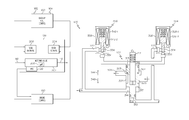
- FIG. 2 is a functional block diagram of a fuel metering unit that may be used to implement the fuel delivery and control system of FIG. 1 ;
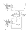
- FIG. 3 is a detailed schematic diagram of the fuel metering unit of FIG. 2 , depicting its configuration when electrical power is being supplied thereto.
- FIG. 1 A simplified schematic diagram of one embodiment of a fuel delivery and control system for a gas turbine engine, such as a turbofan jet aircraft engine, is depicted in FIG. 1 .
- the system 100 includes a fuel source 102 , one or more pumps 104 , 106 , and a fuel metering unit 108 .
- the fuel source 102 which is preferably implemented as a tank, stores fuel that is to be supplied to a gas turbine engine combustor 114 .
- a supply line 116 is coupled to the fuel source 102 and, via the just-mentioned pumps 104 , 106 and fuel metering unit 108 , delivers the fuel to the combustor 114 .
- the supply line 116 is, for convenience, depicted and described with a single reference numeral. However, it will be appreciated that the system is implemented using separate sections of piping, though a single section is certainly not prohibited.
- Each of the one or more pumps 104 , 106 is positioned in flow-series in the supply line 116 and take a suction on the fuel source 102 .
- two pumps are used and include a booster pump 104 , such as a relatively low horsepower centrifugal pump, and a high pressure pump 106 , such as a positive displacement pump.
- the booster pump 104 takes a suction directly on the fuel source 102 and provides sufficient suction head for the high pressure pump 106 .
- the high pressure pump 106 then supplies the fuel at a relatively high pressure to the remainder of the supply line 116 .
- the fuel metering unit 108 is positioned in flow-series in the supply line 116 downstream of the high pressure pump 106 .
- the fuel metering unit 108 is coupled to selectively receive fuel flow commands from two independent fuel flow command sources—a primary fuel flow command source and a secondary fuel flow command source.
- the primary fuel flow command source is a main engine control 150 and the secondary fuel flow command source is a back-up fuel control 160 .
- the engine control 150 which may be, for example, a Full Authority Digital Engine Controller (FADEC), is configured to control the overall operation of the gas turbine engine (or engines), including the flow of fuel from the fuel source 102 to the combustors 114 in each engine.
- FADEC Full Authority Digital Engine Controller
- the engine control 150 receives various input signals and supplies fuel flow increase commands and fuel flow decrease commands to the fuel metering unit 108 to thereby control the fuel flow rate to the combustor 114 .
- the engine control 150 may generate the fuel flow increase and decrease commands in various forms, in the depicted embodiment the engine control 150 generates the fuel flow increase and decrease commands as pulse width modulation (PWM) signals.
- PWM pulse width modulation
- the back-up fuel control 160 may be variously configured, in the depicted embodiment, the back-up fuel control 160 includes a flow decrease user interface 162 and a flow increase user interface 164 .
- the flow decrease user interface 162 and flow increase user interface 164 are each adapted to receive input stimuli from a user, such as a pilot.
- the back-up fuel control 160 is configured to supply fuel flow decrease commands that will result in an decrease in fuel flow when input stimuli is supplied to the flow decrease user interface 162 , and to supply fuel flow increase commands that will result in a increase in fuel flow when input stimuli is supplied to the flow increase user interface 164 .
- the back-up fuel control 160 generates the fuel flow increase and decrease commands as pulse width modulation (PWM) signals.
- PWM pulse width modulation
- the fuel metering unit 108 is configured, in response to the fuel flow increase and decrease commands, to control the flow of fuel to the gas turbine engine combustor 114 .
- a more detailed description of the configuration and operation of the fuel metering unit 108 , and the conditions under which it receives and responds to the fuel flow increase and decrease commands from the primary (e.g., engine control 150 ) or secondary (e.g., back-up fuel control 160 ) fuel flow command sources, will be provided further below. Before doing so, however, a description of the remainder of the depicted fuel supply system will, for completeness, be provided.
- two additional major components are positioned in flow-series in the supply line 116 between the fuel metering unit 108 and the combustor 114 .
- These two major components are a pressurizing and shutoff valve 112 and a flow sensor 118 .
- the pressurizing-and-shutoff valve 112 functions to ensure a minimum system pressure magnitude is in the supply line 116 downstream of the fuel metering unit 108 , and shuts when the pressure falls below this minimum pressure magnitude.
- the flow sensor 118 measures the fuel flow rate to the combustor 114 and generates a flow signal representative of the measured flow rate.
- the system 100 may additionally include a bypass flow line.
- the bypass flow line if included, is preferably connected to the supply line 116 between the high pressure pump 106 and the fuel metering unit 108 , and bypasses a portion of the fuel in the supply line 116 back to the inlet of the high pressure pump 106 , the inlet of the booster pump 104 , or back to the fuel source 102 .
- the bypass line may include a bypass valve that is positioned to selectively bypass fuel flow in the supply line 116 away from the fuel metering unit 108 , and thus the engine combustor 114 . Similar to the fuel metering unit 108 , the bypass valve is preferably controlled in response to valve command supplied from the engine control 150 .
- the fuel metering unit 108 includes a fuel metering valve 202 , a flow increase valve 204 , and a flow decrease valve 206 .
- the fuel metering valve 202 is preferably a hydraulically-operated valve that defines a variable area flow orifice 208 through which a portion of the fuel in the supply line 116 flows. As will be described in more detail further below, the area of the variable area flow orifice 208 is adjusted in response to variable pressure hydraulic fluid that is supplied thereto from the flow increase and flow decrease valves 204 , 206 .
- a position sensor 212 is preferably coupled to the metering valve 202 .
- the position sensor 212 is operable to sense metering valve position and to supply a valve position signal representative thereof to the engine control 150 .
- the position of the metering valve 202 is directly related to the area of the variable area flow orifice 208 , which is directly related to the fuel flow rate to the combustor 114 .
- the position sensor 212 is preferably a dual channel linear variable differential transformer (LVDT), but could be any one of numerous position sensing devices known in the art.
- the position sensor 212 could be a rotary variable differential transformer (RVDT), an optical sensor, or a float-type sensor, just to name a few.
- the flow increase valve 204 and the flow decrease valve 206 are each in fluid communication with the fuel metering valve 202 , and are each coupled to receive hydraulic fluid.
- the flow increase valve 204 is coupled to receive hydraulic fluid at a first fluid pressure from a non-illustrated first hydraulic fluid source
- the flow decrease valve 206 is coupled to receive hydraulic fluid at a second pressure from a non-illustrated second hydraulic fluid source.
- the first hydraulic fluid source is a relatively low pressure hydraulic fluid source such as, for example, the booster pump 104 discharge
- the second hydraulic fluid source is a regulated pressure supplied from the fuel supply line inlet to the fuel metering unit 108 .
- the flow increase valve 204 and the flow decrease valve 206 are also each operable to selectively couple the fuel metering valve 202 to the first hydraulic fluid source and the second hydraulic pressure source, respectively, to thereby vary the area of the variable area flow orifice 208 . More specifically, the flow increase valve 204 is responsive to the above-mentioned fuel flow increase commands to fluidly communicate hydraulic fluid at the first hydraulic fluid pressure to the fuel metering valve 202 . The configuration of the fuel metering valve 202 and the first hydraulic fluid pressure will cause the area of the variable area flow orifice 208 to increase, and thus the flow rate of fuel to the combustor 114 to increase.
- the flow decrease valve 206 is responsive to the above-mentioned fuel flow decrease commands to supply hydraulic fluid at the second hydraulic fluid pressure to the fuel metering valve 202 .
- the configuration of the fuel metering valve 202 and the second hydraulic fluid pressure will cause the area of the variable area flow orifice 208 to decrease, and thus the flow rate of fuel to the combustor 114 to decrease.
- the fuel metering valve 202 includes a valve body 302 and a valve element 304 .
- the valve body 302 includes a fuel inlet port 306 , a fuel outlet port 308 , a first control port 312 , a second control port 314 , and a third control port 316 .
- the fuel inlet port 306 is coupled to receive the flow of fuel from the fuel source 102 , via the pump 106 , and the fuel outlet port 308 is in fluid communication with the pressurizing and shutoff valve 112 .
- the metering valve first control port 312 is coupled to receive hydraulic fluid at the first hydraulic fluid pressure
- the metering valve second control port 314 is coupled to receive hydraulic fluid at the second hydraulic fluid pressure.
- the metering valve third control port 316 is coupled to both the flow increase valve 204 and the flow decrease valve 206 and, as will be described momentarily, selectively receives hydraulic fluid at either the first or second hydraulic fluid pressures.
- the valve element 304 is disposed within the valve body 302 and together the valve element 304 and valve body 302 define the variable area flow orifice 208 .
- the valve element 304 is movable within the valve body 302 to vary the area of the variable area flow orifice 208 , to thereby control the flow of fuel to the engine combustor 114 .
- the valve element 304 is configured to move in response to the overall differential fluid pressure acting on the valve element 304 from the hydraulic fluid supplied to the metering valve first, second, and third control ports 312 , 314 , 316 . More specifically, and as FIG. 3 additionally depicts, the valve element 304 includes a first end 313 , a second end 315 , and an annular control surface 317 .
- the cross sectional areas of the valve element second end 315 and the annular control surface 317 are approximately equal, with each being half the area of first end 313 .
- the above-mentioned position sensor 212 is also depicted as being coupled to the valve element 304 .
- the flow increase valve 204 includes a first flow port 318 , a second flow port 322 , a flow increase valve element 324 , and a flow increase valve actuator 326 .
- the flow increase valve first flow port 318 is coupled to receive hydraulic fluid at the first hydraulic fluid pressure from the above-mentioned, non-illustrated first hydraulic fluid source, and the flow increase valve second flow port 322 is in fluid communication with the fuel metering valve third control port 316 .
- the flow increase valve element 324 is disposed between the flow increase valve first and second flow ports 318 , 322 and is movable between a closed position and an open position. When the flow increase valve element 324 is in the closed position, which is the position depicted in FIG.
- the flow increase valve first flow port 318 is fluidly isolated from the flow increase valve second flow port 322 . Conversely, when the flow increase valve element 324 is in an open position, the flow increase valve first flow port 318 is in fluid communication with the flow increase valve second flow port 322 .
- the flow increase valve element 324 is moved between the closed and open positions by the flow increase valve actuator 326 .
- the flow increase valve actuator 326 is coupled to the flow increase valve element 324 and is coupled to selectively receive the previously described fuel flow increase commands.
- the flow increase valve actuator 326 in response to the fuel flow increase commands, selectively moves the flow increase valve element 324 to either the closed position or an open position.
- the flow increase valve actuator 326 may be implemented using any one of numerous types of actuators, including any one of numerous types of electromechanical, electro-pneumatic, and electro-hydraulic actuators. In the depicted embodiment, however, it is implemented using a spring-loaded, dual-coil solenoid that includes a primary increase valve coil 328 - 1 and a secondary increase valve coil 328 - 2 .
- the flow decrease valve 206 is configured substantially similar to the flow increase valve 204 , and thus also includes a first flow port 332 , a second flow port 334 , a flow decrease valve element 336 , and a flow decrease valve actuator 338 .
- the flow decrease valve first flow port 332 is coupled to receive hydraulic fluid at the second hydraulic fluid pressure from the above-mentioned second hydraulic fluid source, and the second flow port 334 is in fluid communication with the fuel metering valve third control port 316 .
- the flow decrease valve element 336 is disposed between the flow decrease valve first and second flow ports 332 , 334 and is movable between a closed position and an open position. When the flow decrease valve element 336 is in the closed position, which is the position depicted in FIG.
- the flow decrease valve first flow port 332 is fluidly isolated from the flow decrease valve second flow port 334 . Conversely, when the flow decrease valve element 336 is in an open position, the flow decrease valve first flow port 332 is in fluid communication with the flow decrease valve second flow port 334 .
- the flow decrease valve element 336 is moved between the closed and open positions by the flow decrease valve actuator 338 .
- the flow decrease valve actuator 338 is coupled to the flow decrease valve element 336 and is coupled to selectively receive the previously described fuel flow decrease commands.
- the flow decrease valve actuator 338 in response to the fuel flow decrease commands, selectively moves the flow decrease valve element 336 to either the closed position or an open position.
- the flow decrease valve actuator 338 similar to the flow increase valve actuator 326 , may be implemented using any one of numerous types of actuators, including any one of numerous types of electromechanical, electro-pneumatic, and electro-hydraulic actuators. In the depicted embodiment, however, it is implemented using a spring-loaded, dual-coil solenoid that includes a primary increase valve coil 342 - 1 and a secondary increase valve coil 342 - 2 .
- the engine control 150 determines that fuel flow to the engine combustor 114 needs to increase, it will command the fuel metering unit 108 to increase the area of the variable area flow orifice 208 . To do so, the engine control 150 will supply fuel flow increase commands to the flow increase valve 204 , and more specifically to the primary coil 328 - 1 of the flow increase valve actuator 326 . Upon receipt of the flow increase commands, the flow increase valve actuator 326 will move the flow increase valve element 324 to an open position. In the open position, hydraulic fluid at the first hydraulic fluid pressure is communicated through the flow increase valve first and second ports 318 , 322 to the metering valve third control port 316 .
- the metering valve element 304 will move in the direction of arrow 344 , thereby increasing the area of the variable area flow orifice 208 , and concomitantly increasing fuel flow to the combustor 114 .
- the engine control 150 will cease supplying the flow increase commands to the flow increase valve actuator 326 .
- the flow increase valve element 324 will return to its closed position, and the fuel metering valve element 304 will remain in a fixed position.
- the engine control 150 determines that fuel flow to the engine combustor 114 needs to decrease, it will command the fuel metering unit 108 to decrease the area of the variable area flow orifice 208 . To do so, the engine control 150 will supply fuel flow decrease commands to the flow decrease valve 206 , and more specifically to the primary coil 342 - 1 of the flow decrease valve actuator 338 . Upon receipt of the flow decrease commands, the flow decrease valve actuator 338 will move the flow decrease valve element 336 to an open position. In the open position, hydraulic fluid at the second hydraulic fluid pressure is communicated through the flow increase valve first and second ports 332 , 334 to the metering valve third control port 316 .
- the metering valve element 304 will move in the direction of arrow 346 , thereby decreasing the area of the variable area flow orifice 208 , and concomitantly decreasing fuel flow to the combustor 114 .
- the engine control 150 will cease supplying the flow decrease commands to the flow decrease valve actuator 338 .
- the flow decrease valve element 336 will return to its closed position, and the fuel metering valve element 304 will remain in a fixed position. It will thus be appreciated that as long as the system pressures remain relatively constant, the position of the fuel metering valve element 304 will remain unchanged.
- the metering valve 202 will remain in a fixed position in the unlikely event that the engine control 150 is unable to control the flow increase and flow decrease valves 204 , 206 .
- Various events are postulated to result in such an occurrence. For example, it is postulated that electrical power to the engine control 150 may be lost or otherwise become unavailable, or that the engine control 150 itself may become lost or otherwise unavailable, or that one or both of the primary coils 328 - 1 , 342 - 1 may become lost or otherwise unavailable.
- the system 100 is configured such that, not only will the metering valve 202 “fail fixed,” but also to allow a user, such as a pilot, to control fuel flow to the engine combustor 114 via the back-up control 160 .
- the pilot will supply appropriate input stimuli to the flow increase user interface 164 .
- the back-up valve control 160 in response to the supplied input stimuli, will supply fuel flow increase commands to the fuel increase valve 204 , and more specifically to the secondary coil 328 - 2 of the flow increase valve actuator 326 . This will cause the metering valve element 304 to move in the direction of arrow 344 , thereby increasing the area of the variable area flow orifice 208 , and concomitantly increasing fuel flow to the combustor 114 .
- the back-up control 160 will cease supplying the fuel flow increase commands to the flow increase valve 204 , and the fuel metering valve element 304 will remain in a fixed position.
- the pilot will supply appropriate input stimuli to the flow decrease user interface 162 .
- the back-up control 160 will supply fuel flow decrease commands to the flow decrease valve 206 , and more specifically to the secondary coil 342 - 2 of the flow decrease valve 206 . This will cause the metering valve element 304 to move in the direction of arrow 346 , thereby reducing the area of the variable area flow orifice 208 , and concomitantly decreasing fuel flow to the combustor 114 .
- the back-up valve control 160 will cease supplying the fuel flow decrease commands to the flow decrease valve 206 , and the fuel metering valve element 304 will remain in a fixed position.
Landscapes
- Engineering & Computer Science (AREA)
- Chemical & Material Sciences (AREA)
- Combustion & Propulsion (AREA)
- Mechanical Engineering (AREA)
- General Engineering & Computer Science (AREA)
- Flow Control (AREA)
- Magnetically Actuated Valves (AREA)
Priority Applications (2)
| Application Number | Priority Date | Filing Date | Title |
|---|---|---|---|
| US13/490,169 US9140190B2 (en) | 2012-06-06 | 2012-06-06 | Gas turbine engine fuel metering valve adapted to selectively receive fuel flow increase/decrease commands from the engine control and from the back-up fuel control |
| EP20130167390 EP2672090A2 (fr) | 2012-06-06 | 2013-05-10 | Système de commande de secours et fixation sécurisée de soupape de dosage de carburant |
Applications Claiming Priority (1)
| Application Number | Priority Date | Filing Date | Title |
|---|---|---|---|
| US13/490,169 US9140190B2 (en) | 2012-06-06 | 2012-06-06 | Gas turbine engine fuel metering valve adapted to selectively receive fuel flow increase/decrease commands from the engine control and from the back-up fuel control |
Publications (2)
| Publication Number | Publication Date |
|---|---|
| US20130327044A1 US20130327044A1 (en) | 2013-12-12 |
| US9140190B2 true US9140190B2 (en) | 2015-09-22 |
Family
ID=48537759
Family Applications (1)
| Application Number | Title | Priority Date | Filing Date |
|---|---|---|---|
| US13/490,169 Active 2034-07-08 US9140190B2 (en) | 2012-06-06 | 2012-06-06 | Gas turbine engine fuel metering valve adapted to selectively receive fuel flow increase/decrease commands from the engine control and from the back-up fuel control |
Country Status (2)
| Country | Link |
|---|---|
| US (1) | US9140190B2 (fr) |
| EP (1) | EP2672090A2 (fr) |
Cited By (4)
| Publication number | Priority date | Publication date | Assignee | Title |
|---|---|---|---|---|
| US20200156805A1 (en) * | 2018-11-16 | 2020-05-21 | Rolls-Royce Corporation | Secured backup feature for an embedded system |
| US20210239054A1 (en) * | 2020-02-05 | 2021-08-05 | Hamilton Sundstrand Corporation | Metering pump system |
| US11519340B2 (en) * | 2018-12-21 | 2022-12-06 | Safran Aircraft Engines | System and method for controlling a speed of rotation of an aircraft turbine engine with fault management |
| US11746711B2 (en) | 2021-08-12 | 2023-09-05 | Pratt & Whitney Canada Corp. | Pulse width modulation drive for staged fuel manifolds |
Families Citing this family (3)
| Publication number | Priority date | Publication date | Assignee | Title |
|---|---|---|---|---|
| FR2970303B1 (fr) * | 2011-01-06 | 2014-06-13 | Snecma | Circuit de carburant de turbomachine aeronautique a vanne de regulation de pression de carburant |
| US9965056B2 (en) | 2016-03-02 | 2018-05-08 | FiftyThree, Inc. | Active stylus and control circuit thereof |
| FR3088365B1 (fr) * | 2018-11-13 | 2020-12-25 | Safran Aircraft Engines | Unite de dosage de carburant pour un moteur d’aeronef |
Citations (23)
| Publication number | Priority date | Publication date | Assignee | Title |
|---|---|---|---|---|
| US2628472A (en) | 1949-02-03 | 1953-02-17 | Bendix Aviat Corp | Fuel metering system for gas turbine engines |
| US3808801A (en) | 1971-01-06 | 1974-05-07 | Lucas Industries Ltd | Fuel control system for gas turbine engine |
| US3946551A (en) | 1974-01-17 | 1976-03-30 | United Technologies Corporation | Pumping and metering system |
| US4256017A (en) | 1979-04-05 | 1981-03-17 | The Bendix Corporation | Differential area electrohydraulic doser actuator |
| US4300347A (en) * | 1979-03-01 | 1981-11-17 | Lucas Industries Limited | Shut-off valve arrangement for a gas turbine engine fuel |
| US4342443A (en) | 1979-10-26 | 1982-08-03 | Colt Industries Operating Corp | Multi-stage fuel metering valve assembly |
| US4386553A (en) | 1980-10-27 | 1983-06-07 | The Bendix Corporation | Control system for doser actuator |
| US4640093A (en) | 1985-09-03 | 1987-02-03 | Allied Corporation | Fuel metering system |
| US4951459A (en) | 1988-08-30 | 1990-08-28 | Allied-Signal Inc. | Methods for metering fluid and apparatus for use therewith |
| GB2305975A (en) | 1995-10-07 | 1997-04-23 | Lucas Ind Plc | Fuel system for a gas turbine engine |
| US6205766B1 (en) * | 1997-07-11 | 2001-03-27 | Lucas Industries | Fluid flow valve and fluid flow system |
| US6381946B1 (en) * | 2000-05-22 | 2002-05-07 | Woodward Governor Company | Two stage fuel metering system for gas turbine |
| US20020078693A1 (en) * | 2000-12-22 | 2002-06-27 | Snecma Moteurs | Hydromechanical system for limiting excess engine speed |
| US6912837B2 (en) | 2001-10-02 | 2005-07-05 | Honeywell International Inc. | Fail fixed fuel metering device and method for providing bumpless transfer to backup |
| US6996969B2 (en) | 2003-09-09 | 2006-02-14 | Goodrich Pump & Engine Control Systems, Inc. | Multi-mode shutdown system for a fuel metering unit |
| US20070234732A1 (en) * | 2006-04-07 | 2007-10-11 | Honeywell International | Gas turbine engine fuel control system having a transfer valve and a shutoff valve and a common controller therefor |
| US7526911B2 (en) | 2006-02-03 | 2009-05-05 | Rolls-Royce Corporation | Gas turbine engine fuel system with fuel metering valve |
| US7836676B2 (en) * | 2007-06-04 | 2010-11-23 | Honeywell International Inc. | Fuel metering valve back-up position control system |
| US20100293919A1 (en) * | 2009-05-22 | 2010-11-25 | Hamilton Sundstrand Corporation | Dual-pump fuel system and method for starting a gas turbine engine |
| US20110173988A1 (en) | 2008-11-13 | 2011-07-21 | Sweet David H | Adaptive fail-fixed system for fadec controlled gas turbine engines |
| US20120067022A1 (en) * | 2010-09-08 | 2012-03-22 | Honeywell International Inc. | Gas turbine engine fuel control thrust control override system |
| US20120261000A1 (en) * | 2011-04-12 | 2012-10-18 | Honeywell International Inc. | Fuel flow divider and ecology system for a gas turbine engine fuel flow control system |
| US20120266600A1 (en) * | 2009-10-06 | 2012-10-25 | Snecma | Fuel feed circuit for an aeroengine |
-
2012
- 2012-06-06 US US13/490,169 patent/US9140190B2/en active Active
-
2013
- 2013-05-10 EP EP20130167390 patent/EP2672090A2/fr not_active Withdrawn
Patent Citations (23)
| Publication number | Priority date | Publication date | Assignee | Title |
|---|---|---|---|---|
| US2628472A (en) | 1949-02-03 | 1953-02-17 | Bendix Aviat Corp | Fuel metering system for gas turbine engines |
| US3808801A (en) | 1971-01-06 | 1974-05-07 | Lucas Industries Ltd | Fuel control system for gas turbine engine |
| US3946551A (en) | 1974-01-17 | 1976-03-30 | United Technologies Corporation | Pumping and metering system |
| US4300347A (en) * | 1979-03-01 | 1981-11-17 | Lucas Industries Limited | Shut-off valve arrangement for a gas turbine engine fuel |
| US4256017A (en) | 1979-04-05 | 1981-03-17 | The Bendix Corporation | Differential area electrohydraulic doser actuator |
| US4342443A (en) | 1979-10-26 | 1982-08-03 | Colt Industries Operating Corp | Multi-stage fuel metering valve assembly |
| US4386553A (en) | 1980-10-27 | 1983-06-07 | The Bendix Corporation | Control system for doser actuator |
| US4640093A (en) | 1985-09-03 | 1987-02-03 | Allied Corporation | Fuel metering system |
| US4951459A (en) | 1988-08-30 | 1990-08-28 | Allied-Signal Inc. | Methods for metering fluid and apparatus for use therewith |
| GB2305975A (en) | 1995-10-07 | 1997-04-23 | Lucas Ind Plc | Fuel system for a gas turbine engine |
| US6205766B1 (en) * | 1997-07-11 | 2001-03-27 | Lucas Industries | Fluid flow valve and fluid flow system |
| US6381946B1 (en) * | 2000-05-22 | 2002-05-07 | Woodward Governor Company | Two stage fuel metering system for gas turbine |
| US20020078693A1 (en) * | 2000-12-22 | 2002-06-27 | Snecma Moteurs | Hydromechanical system for limiting excess engine speed |
| US6912837B2 (en) | 2001-10-02 | 2005-07-05 | Honeywell International Inc. | Fail fixed fuel metering device and method for providing bumpless transfer to backup |
| US6996969B2 (en) | 2003-09-09 | 2006-02-14 | Goodrich Pump & Engine Control Systems, Inc. | Multi-mode shutdown system for a fuel metering unit |
| US7526911B2 (en) | 2006-02-03 | 2009-05-05 | Rolls-Royce Corporation | Gas turbine engine fuel system with fuel metering valve |
| US20070234732A1 (en) * | 2006-04-07 | 2007-10-11 | Honeywell International | Gas turbine engine fuel control system having a transfer valve and a shutoff valve and a common controller therefor |
| US7836676B2 (en) * | 2007-06-04 | 2010-11-23 | Honeywell International Inc. | Fuel metering valve back-up position control system |
| US20110173988A1 (en) | 2008-11-13 | 2011-07-21 | Sweet David H | Adaptive fail-fixed system for fadec controlled gas turbine engines |
| US20100293919A1 (en) * | 2009-05-22 | 2010-11-25 | Hamilton Sundstrand Corporation | Dual-pump fuel system and method for starting a gas turbine engine |
| US20120266600A1 (en) * | 2009-10-06 | 2012-10-25 | Snecma | Fuel feed circuit for an aeroengine |
| US20120067022A1 (en) * | 2010-09-08 | 2012-03-22 | Honeywell International Inc. | Gas turbine engine fuel control thrust control override system |
| US20120261000A1 (en) * | 2011-04-12 | 2012-10-18 | Honeywell International Inc. | Fuel flow divider and ecology system for a gas turbine engine fuel flow control system |
Non-Patent Citations (1)
| Title |
|---|
| Pratt & Whitney A United Technologies Company, Flight Operations Support; Operating Instructions for the PW4000 Series Commercial Turbofan Engines in the A300-600 and A310 Airplanes; Nov. 15, 1993 Revision 8-Jun. 30, 2008. |
Cited By (6)
| Publication number | Priority date | Publication date | Assignee | Title |
|---|---|---|---|---|
| US20200156805A1 (en) * | 2018-11-16 | 2020-05-21 | Rolls-Royce Corporation | Secured backup feature for an embedded system |
| US11440677B2 (en) * | 2018-11-16 | 2022-09-13 | Rolls-Royce Corporation | Secured backup feature for an embedded system |
| US11519340B2 (en) * | 2018-12-21 | 2022-12-06 | Safran Aircraft Engines | System and method for controlling a speed of rotation of an aircraft turbine engine with fault management |
| US20210239054A1 (en) * | 2020-02-05 | 2021-08-05 | Hamilton Sundstrand Corporation | Metering pump system |
| US11629652B2 (en) * | 2020-02-05 | 2023-04-18 | Hamilton Sundstrand Corporation | Metering pump system |
| US11746711B2 (en) | 2021-08-12 | 2023-09-05 | Pratt & Whitney Canada Corp. | Pulse width modulation drive for staged fuel manifolds |
Also Published As
| Publication number | Publication date |
|---|---|
| US20130327044A1 (en) | 2013-12-12 |
| EP2672090A2 (fr) | 2013-12-11 |
Similar Documents
| Publication | Publication Date | Title |
|---|---|---|
| US7836676B2 (en) | Fuel metering valve back-up position control system | |
| US9140190B2 (en) | Gas turbine engine fuel metering valve adapted to selectively receive fuel flow increase/decrease commands from the engine control and from the back-up fuel control | |
| US7966995B2 (en) | Dual level pressurization control based on fuel flow to one or more gas turbine engine secondary fuel loads | |
| US9234465B2 (en) | Fuel flow divider and ecology system for a gas turbine engine fuel flow control system | |
| US8256222B2 (en) | Direct metering fuel control with integral electrical metering pump and actuator servo pump | |
| US6981359B2 (en) | Centrifugal pump fuel system and method for gas turbine engine | |
| US8128378B2 (en) | Dual mode compensation for variable displacement pump fluid metering system | |
| US9353688B2 (en) | High pressure, multiple metering zone gas turbine engine fuel supply system | |
| US8291886B2 (en) | Actuator flow compensated direct metering fuel control system and method | |
| US9068509B2 (en) | Gas turbine engine fuel control thrust control override system | |
| EP2535644B1 (fr) | Systèmes de commande de carburant de chambre de combustion avec ensemble répartiteur d'écoulement | |
| EP2485109B1 (fr) | Système de carburant de mesure directe avec débit de servo constant | |
| CN107074374B (zh) | 用于流体分配系统的泵权限切换装置 | |
| EP3022426B1 (fr) | Système de régulation de pression de dosage parallèle en série pour un système de dosage de combustible efficace thermiquement | |
| US9243565B2 (en) | Gas turbine engine fuel system metering valve | |
| KR101656119B1 (ko) | 개선된 레귤레이터 장치를 구비한 연료 유량계 | |
| US11788476B1 (en) | Fluid system with variable pump discharge pressure and method | |
| EP2025901B1 (fr) | Système de dosage de carburant avec une introduction de chaleur minimale | |
| US7841841B2 (en) | Flow prioritizing valve system | |
| UA75576C2 (uk) | Система вприскування палива у турбомашинах | |
| EP4283111B1 (fr) | Systèmes de dosage de carburant à double soupape | |
| EP2025933B1 (fr) | Compensation à mode double pour système de mesure de pompe à déplacement variable | |
| US20240240631A1 (en) | Direct control for variable displacement pumps | |
| RU2476702C2 (ru) | Система подачи топлива в газотурбинный двигатель |
Legal Events
| Date | Code | Title | Description |
|---|---|---|---|
| AS | Assignment |
Owner name: HONEYWELL INTERNATIONAL INC., NEW JERSEY Free format text: ASSIGNMENT OF ASSIGNORS INTEREST;ASSIGNORS:PORTOLESE, LARRY;KLINE, GREGORY;FUTA, PAUL W.;AND OTHERS;REEL/FRAME:028330/0695 Effective date: 20120606 |
|
| STCF | Information on status: patent grant |
Free format text: PATENTED CASE |
|
| MAFP | Maintenance fee payment |
Free format text: PAYMENT OF MAINTENANCE FEE, 4TH YEAR, LARGE ENTITY (ORIGINAL EVENT CODE: M1551); ENTITY STATUS OF PATENT OWNER: LARGE ENTITY Year of fee payment: 4 |
|
| MAFP | Maintenance fee payment |
Free format text: PAYMENT OF MAINTENANCE FEE, 8TH YEAR, LARGE ENTITY (ORIGINAL EVENT CODE: M1552); ENTITY STATUS OF PATENT OWNER: LARGE ENTITY Year of fee payment: 8 |