US914565A - Wagon dump and elevator. - Google Patents
Wagon dump and elevator. Download PDFInfo
- Publication number
- US914565A US914565A US46067608A US1908460676A US914565A US 914565 A US914565 A US 914565A US 46067608 A US46067608 A US 46067608A US 1908460676 A US1908460676 A US 1908460676A US 914565 A US914565 A US 914565A
- Authority
- US
- United States
- Prior art keywords
- bar
- clutch
- shaft
- platform
- lever
- Prior art date
- Legal status (The legal status is an assumption and is not a legal conclusion. Google has not performed a legal analysis and makes no representation as to the accuracy of the status listed.)
- Expired - Lifetime
Links
- 238000004804 winding Methods 0.000 description 9
- 210000003128 head Anatomy 0.000 description 4
- KWVIBDAKHDJCNY-UHFFFAOYSA-N 20alpha-atisine Natural products C12CCC3(C(C4=C)O)CCC4CC3C11CCCC2(C)CN2CCOC21 KWVIBDAKHDJCNY-UHFFFAOYSA-N 0.000 description 1
- 241000282326 Felis catus Species 0.000 description 1
- 241000276425 Xiphophorus maculatus Species 0.000 description 1
- 238000010276 construction Methods 0.000 description 1
- 210000003027 ear inner Anatomy 0.000 description 1
- 230000000694 effects Effects 0.000 description 1
- 239000002184 metal Substances 0.000 description 1
- 108010085990 projectin Proteins 0.000 description 1
- 230000001105 regulatory effect Effects 0.000 description 1
Images


Classifications
-
- B—PERFORMING OPERATIONS; TRANSPORTING
- B65—CONVEYING; PACKING; STORING; HANDLING THIN OR FILAMENTARY MATERIAL
- B65G—TRANSPORT OR STORAGE DEVICES, e.g. CONVEYORS FOR LOADING OR TIPPING, SHOP CONVEYOR SYSTEMS OR PNEUMATIC TUBE CONVEYORS
- B65G67/00—Loading or unloading vehicles
- B65G67/02—Loading or unloading land vehicles
- B65G67/24—Unloading land vehicles
- B65G67/32—Unloading land vehicles using fixed tipping installations
- B65G67/34—Apparatus for tipping wagons or mine cars
- B65G67/36—Apparatus for tipping wagons or mine cars endwise
- B65G67/40—Apparatus for tipping wagons or mine cars endwise toward one end only
Definitions
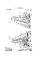
- Fig. 1 is a front elevation of my improved mechanism. is an end view of the machine, the internal gear wheel'heing shown in section.
- Fig. 3 is a vertical sectionthrough the base of the inachine at line 3-3 of Fig. 1, showing in elevation thegopposite side of the framework and mechanism connected therewith that is represented in F ig. 2.
- Fig. 4 is a horizontal section at line 4 4 of Fig. 2.
- Fig. 5 and Fig. 6 are details, illustrating different ositions of the shifting mechanism, Fig. 5 s owing the parts in the position assu-ined just prior to the. Withdrawal of the c-luteh from engagement ⁇ with either the. internal gearor the Worm.
- Fig. 7 is a perspective view of the outer end of the slotted shifting plate.
- Fig. 8 is a detail of the short link pivoted to the shifting lever and engaging the slotted plate shown in Fig. 7.
- 10 indicates a rectangular frame forming the base of the machine.
- Each frame 11-#12 indicates two supporting frames of ordinary construction secured upon. the base near opposite ends thereof.
- Each frame 11-#12 consists, as shown, of bars se Specification of Letters Patent.
- the base and supporting frames are substantially the same asshown in my allowed application, filed January ⁇ 27, 1908, Serial Number 412,854, and much ofthe operating p mechanism about to .be describedis also the same as in that application and hence but a brlef description of such parts as are' found therein will suffice here.
- t2,1 indicates the clutch on the drive shaft 15, the clutch being so connected ith the shaft as to lturn therewith and alsoheing free to move longitudinally on the shaft.
- the clutch is located on the shaft betvveen the Worin 17 and the internal gearL 22 r and has its ends adaptedtoengage 'with either of said parts.
- 35 indicates a rod pivotally secured to the t'op of the pivoted lever 29 through which an attendant may operate such lever to throw the clutch 21 into engagement with either the worm 17 or the internal gear 22.
- the movable platform 36 indicates bars each ri idly secured at its upper end to the upper en of one of the vertical end frames and at its lower end-rigidly connected with the base.
- the movable platform is suitably connected with each of these rigid bars by any suitable guiding devices, such, for example, as the loops 37 (see Fig. 2), each loop being secured to' and projecting from one end of the movable frame.
- the lower slot 42 receive'sthe rod 19 that carries the worm wheel 18 and the two winding drums.
- This roller is provided with a projecting end of the end-frame 12, preferably around the end of the pivot 39 and secured at its lower end to a laterally-extending ar1n'49 formed with or connected to the pivoted shifting lever 29.
- 50 indicates a slide, preferably in the form of a block, arranged. so as to be freely movable upand down on the long pivoted lever 38. ⁇
- This slide carries means for detachably engaging the short section of chain 48, such means being preferably in the form of a hook 51, as indicated.
- the height to which the platform is to .be lifted can of coarse be regulated by the point of attac-lnA .ment of the slide 50 ⁇ to the short chain e8.l Then it is desired to cause the descent of the :movable platform, the operator, through the rod 35, will shift the lever 29 so as to cause an engagement of the clutch with the internal gear. 22., and such movement ⁇ will throw the 'lt pin aback to the endef theupper portion of the slot 4.3.
Landscapes
- Engineering & Computer Science (AREA)
- Aviation & Aerospace Engineering (AREA)
- Mechanical Engineering (AREA)
- Transmission Devices (AREA)
Description
F. GAHM WAGON DUMP AND BLEVTOR. APPLIOATION FILED Nov.z,19o.
Patented Mar. 9,1909.
3 SHEETS-SHEET 1.
E'. GHM.
WAGDN DUMP AND ELEVATOB.
APPLICATION FILED Nov.2,19os.
Patented Mar, 9, 1909.
/Q @If ,w
QQ. i? Q,
FL GAHM.
WAGON DUMPAAND BLEVATOB.. APPLICATION FILED NOV.2, 1908.
914,565. Patented M3119, 199.
3 SHEETS-SHEET 3.
PV "VN OVP 48+ "fll d Wsw 4 'm if d @7 Nonms PETERS. lNc Lmio wMwNoToN D C -A FRANK GAHM, OF STREATOR, ILLINOIS.
WAGON DUMP AND ELEVATOR.
Application led November 2 To all ulem it 'may concern:
it knoe-iitliat I, FRANK GAHM, a citizen of the United States, residing at Streator, in the l'county of Lasalle, State of Illinois, have invented certain new land useful I1nprove ments in Wagon Dumps and Elevators, of which the foliowingr is a specification, reference being-j had to the accompanying drawings.
'This iiwention relates to devices forraising the front end of au vehicle in order to enable the contents to he readily dumped therefrom. i
It has for its leading object to provide improved inea-ns for automatically throwing' the operative mechanism out of action at the predetermined limit of the upward movement oi' the platform that supports the front wheels of the vehicle and also at the conclusion of its downward movement. I accomplish this ohject by the means shown in thev drawings and hereinafter more speeiiically described.
'lhat which I believe to be new will he set forth in the claims.
In the drawings :#-Figure 1 is a front elevation of my improved mechanism. is an end view of the machine, the internal gear wheel'heing shown in section. Fig. 3 is a vertical sectionthrough the base of the inachine at line 3-3 of Fig. 1, showing in elevation thegopposite side of the framework and mechanism connected therewith that is represented in F ig. 2. Fig. 4 is a horizontal section at line 4 4 of Fig. 2. Fig. 5 and Fig. 6 are details, illustrating different ositions of the shifting mechanism, Fig. 5 s owing the parts in the position assu-ined just prior to the. Withdrawal of the c-luteh from engagement `with either the. internal gearor the Worm. Some of the part-s are shown in bro ken lines. Fig. 7 is a perspective view of the outer end of the slotted shifting plate. Fig. 8 is a detail of the short link pivoted to the shifting lever and engaging the slotted plate shown in Fig. 7. v v
Referring to the several figures of the drawings, in which corresponding parts are indicated by the same reference characters, 10 indicates a rectangular frame forming the base of the machine.
11 and 12 indicate two supporting frames of ordinary construction secured upon. the base near opposite ends thereof. Each frame 11-#12 consists, as shown, of bars se Specification of Letters Patent.
, 190s. serial :va-460,676.
Patented March 9, 1969.
cured together near their upper ends by a. plate 13.
The base and supporting frames are substantially the same asshown in my allowed application, filed January `27, 1908, Serial Number 412,854, and much ofthe operating p mechanism about to .be describedis also the same as in that application and hence but a brlef description of such parts as are' found therein will suffice here.
14 indicates a Ivertieally-arranged metal frame suitably secured to the base lOjust beyond the out-er face of the frame 12 already referred to. l y
15 indicates a drive shaft suitably mounted in bearings 16, the ends of said driveshaft beine squared as indicated to adapt it to have connection at either end. to an ordinary tumbling rod. v
17 indicates a Worm loosely mounted on the driveshaft, which vorm meshes witha worm-wheel 18 fast on the end of a shaft- 19l that extends longitudinally of the base'and is journaled at its opposite end near the upright frame 11 in a suitable bearing 2,0 (see Fie'. 1).
t2,1 indicates the clutch on the drive shaft 15, the clutch being so connected ith the shaft as to lturn therewith and alsoheing free to move longitudinally on the shaft. ,As
shown in Fig. 2, that portion of the shaft on which the clutch moves is squared.'
22 indicates an internal gear of comparatively large size loosely mounted on. the drive shaft. The clutch is located on the shaft betvveen the Worin 17 and the internal gearL 22 r and has its ends adaptedtoengage 'with either of said parts. n i
23 indicates a pinion formed with or made fast to the end of the sleeve on which'is formed the Worm 17.
24 indicates anotherv pinion meshing vwith the pinion 23, said pinion 24 being fast on the end of a counter shaft 25 suitably mounted in bearings 26 and 27. rAt. the opposite end of the shaft 25 is mounted another pinion 2S which engages the internal gear 22.
29 indicates a lever pivoted to ltheun er bar of the frame 14, as clearly sho nin ig. 2, and having a suitable engagement at its lower end with the double-ended clutch 21, -whereby this lever, by being rocked upon its pivot, may cause such clutch to engage either with the Worm vor the internallgea'r.
'All of the ion ei is snhseaie plication t-he shaft 19. is a short shaft having `mounted upon it a single 'winding drum,
Whereas in my `present application it is shown y asa long shaft upon which are mounted two windingdrums 30 and 31 (see Fig. 1).
32 indicates the movable platform upon which the front u heels of a wagon are adapted to be driven. At each end of this platform is secured one end of a chain 'which passes over a ulley mounted in the upper end of o`ne oftlie upright frames and having its other end secured to one of the drums referred to.. `The chain adjacent to the u ht frame 11 is indicated by 33, and t e Aot er'chain by 34.
35 indicates a rod pivotally secured to the t'op of the pivoted lever 29 through which an attendant may operate such lever to throw the clutch 21 into engagement with either the worm 17 or the internal gear 22.
36 indicates bars each ri idly secured at its upper end to the upper en of one of the vertical end frames and at its lower end-rigidly connected with the base. The movable platform is suitably connected with each of these rigid bars by any suitable guiding devices, such, for example, as the loops 37 (see Fig. 2), each loop being secured to' and projecting from one end of the movable frame.
, 38 indicates a long bar pivotally connected 'at its u per end at 39 to the outer face of the vertical) endfframe 12. This bar 38, when the movable platform 32 is in its lower posi-A tion, as in Fig. 2, will stand at a suitable inclination, being practically parallel with the bar of the inchned frame that is, as shown, somewhat sharply inclined. At its lower end this bar 38 is given a considerable curve, as clearly shown ,in Fig. 2, the lower end entering or otherwise engaging the adjacent loop 37, as shown in Fig. 4.
40.indicates a bar pivotally attached at its inner end to the lower end of the long bar 38 below the loop 37 and at its forward end provided -with an enlarged plate portion 41 in which is formed two slots, the lower of said slots 42 being straight and open at its' forward end, and the other of said slots, which is indicated by 43, having its inner portion yhigher than itsv for-ward portion, the two end portions of the slot being connected by a diagonal portion,-as clear y shown in Figs.. 3
and 7. The lower slot 42 receive'sthe rod 19 that carries the worm wheel 18 and the two winding drums. y
44 ind'cates a link pivotally connected at its inner end to the lower end of the shifting lever 29 and at its other end .is provided with a fixed ,inl 45 that projects from both sides of said link. This link'lies close along `against the slotted head or plate portion 41, and the pin 45 proj ectingout from that side of the link neXt to the said slotted head or lthe said plate portion enters the irregular-shaped upper slot 43.
46 indicates a small roller fixedly secured upon a reduced portion of the rod 19, such roller lying immediatelynext to the inner face of the lower bar of the small frame 14.
4This roller is provided with a projecting end of the end-frame 12, preferably around the end of the pivot 39 and secured at its lower end to a laterally-extending ar1n'49 formed with or connected to the pivoted shifting lever 29. 50 indicates a slide, preferably in the form of a block, arranged. so as to be freely movable upand down on the long pivoted lever 38.` This slide carries means for detachably engaging the short section of chain 48, such means being preferably in the form of a hook 51, as indicated. l
lt will be understood from the description given in my said former application that when the clutch is in engagement with the worm the shaft 19 will be driven in a direction to Wind up the lifting chains so as to elevate the platform 32, while, when the clutch is in enga ement with the internal ear, said shaft wi l be reversely rotated to a ow the lifting chains to unwind tolpermit the descent of latform, and I need not therefore more ful y describe this operation.
Referring now to the means em loyed for 'effecting the throwing out of the c utch from engagement with either the worm or the internal gear, when' the parts are in the position shown in Fig. 2, wherein the clutchis in engagement with the Worm and the platform is lowered, the pin 45 will be at the forward end of the lower portion of the slot 43 but will be gradually withdrawn along said slot as the platform rises, owing to the loop pressing on the curved rear edge-of the long pivoted lever 38, causing such lever to swing slightly`Tl forward-and l mean by forward toward lthat edge of the machine nearest the rod 19,-- and, as the platform continues to rise, the loop will come in contact with the slide 50, forcing said slide upward on said bar 38, and,
through the short section of chain 48, lwith which the slide is' connected through the hook 51, a pull will be exerted on thev arm 49 that pivot, and, through the link 44, that is pivoted to the lower end of the lever, causing the pin ,to ride up the inclined portion of the slot 43,-
where it remains at rest at about the beginning of the straight u per portion of said slot. The shifting of this ever 29 in. this manner throws the clutch out of engagement with i f Lend, will be moved back vsufliciently to cause erases the worin, leaving it midway between, the] worm and the internal gear, so that the further rotation of such clutch and the shaft on which it is mounted has vno further effect in the way of causing a movement in either direction -of the movable platform. The height to which the platform is to .be lifted can of coarse be regulated by the point of attac-lnA .ment of the slide 50`to the short chain e8.l Then it is desired to cause the descent of the :movable platform, the operator, through the rod 35, will shift the lever 29 so as to cause an engagement of the clutch with the internal gear. 22., and such movement `will throw the 'lt pin aback to the endef theupper portion of the slot 4.3. The continued rotation yof the drive shaft will then, as already fully de- Veribed in my said former application, cause a reverse vrotation of the rod 19 so as to unwind the lifting chainstherefrom.-l New, as'the platform descends,- the loop on its end that embraces the long ivotedlever 38, will, as'it strikes the curved ower portion of suoli bar, cause the harto turn on its pivot 39 slightly whereby the bar et), connectedto its lower the pin. to move down thefinclined part of the slot 43 into position to be engaged by the tooth 4?011 the small roller 46. Suchengagement, as the'rollervcontinues to rotate, will cause a forward pull on the link 44 that carries such pin and will necessarilyT cause a pulling on the lower end lof the' shifting lever 29z that will ldraw the clutch outl of engagement with the internal gear, such clutch re maining free of the internal gear and freelof the worm until it is again shifted by the operator through the rod'35.
By the means described, l provide very simple and effective means for automatically shifting the clutch out'ofengagement with either of the driving devices.
What I claim as my invention and desire to secure by Letters Patent is:-
1. The combination with a movable platform, a lifting chain therefor, a rotatable winding shaft with which Said chain is connected, two sets of mechanism adapted to rotate said shaft in dierent directions, a drive shaft, a clutch on said drive shaft adapted to engage either of said sets of mechanism, and a pivoted lever for shifting said clutch, of a swinging bar, means secured to one end of said platform and slidingly engaging said bar and adapted to canse said bar to swing when near one end of the movement of said platform, a longitudinally movable bar connected to said swinging bar and provided with a head having a slot, a link pivotally aff tached to said shifting lever, a pin carried by said link and extending into said slot, and a rotating device adapted to engage said pin to pull the link forward, and, through the said shifting lever, move the clutch out of engagenected, two sets of i'neclialiiisl pull the lin-k forwarihjandjt ir'oiiglithe'said form, a lifting chainthlerefor, 'a rotatable ywinding' shaft' with which 's'aidchain' is' con# ment with one of said sets of mechanism.
Z.' The combinationwitlif'ain: forni, a lifting chainwtlierforj wmdingshaft with whijcl'i aid' in" conf y M 4adapted torotate said shaft indiiferentkdireciions,adrivo shaft, a clutch on said driveshaft al'aptedito engage either of said sett y'echanism','faiiol a pivot-ed lever for shi in,D i l clutch, swinging. bar, means set-n" 'd to oneei l of said .platform and slidingly efiigaging.` said-bai' and adapted to causels dbar'toswingwhen near one end of the vin ent'oi dipl'atform, a longitudinally e" connectedto said swinging-bar` icvided""witlrh` n head having a slot thatis higher at vmie""enfd than at the other, a link pivotallyattached to ysaid shifting leverjapin carried by saidv linkand extendingintosaidsl t, and 'afiou l tating device adaptedtoen 'age'said pin :to
shifting lever, move theclut'ch out ofengagement with one of saidsets of n'i'echanisni. fr 3. The combinationwitlii;afmovabl-e'platy n nected,` two sets of niechanismladapted to rotate said shaft in different directionaa drive shaft ,la clutch on saiddrive shaft adapted to engage either of said .setsv of niechanis'nnand a pivoted lever for shifting S'aid clutch, yofa' swinging bar, meansconnectedtooneend'of said platform and slidinglyy engagingrsaijd bar and adapted' to canse said 'bar tofswingwhen near one-end of the movement" of's'a'id'-l-lat- M form, a link pivotally attached to saids i-i-ft- T100 ing lever, a pin secured tov said link, arotat ing device adapted toeng'ag'e said .pin .topll the link-forward, and, ,throughthe said shifting lever, m'ove the clutch,outofengagenient with one of' said (sets Aof mechanismfand means connected with saidswingingbar for normally holding said pin'out of contact with'- said rotating device and at a predetermined time allowing said in to be moved to a position to be engaged y said rotating device.
e, lThe combination with a movable platform, a lifting chain therefor, a rotatable winding shaft with which said chain is connected, two sets of mechanism adapted to rotate said shaft in different directions, a drive shaft, a clutch on said drive shaft ada ted to engage either of said sets of mecihanism, and a pivoted lever for shifting said clutch, of a swinging bar curved at its lower end, means projecting from one end of the said movable platform and embracing said swinging bar and adapted to move said bar when in contact with said curved portieri of the bar, a link pivotally attached to said shifting lever, a rotatable device adapted to longitudinally move said link and through the said shifting lever 4move the 'clutch out of engagement 4 with one of said sets of mechanism, and means connected with said swinging bar for normally 13o fl-O 5 said rotating device and at apredetermined time causing such engagemen 5. The combinatlon with winding shaft with which said chain is connected, two sets of mechanism adapted to rotate said shaft in different directions, aI
drive-shaft, a clutchon said drive shaft adaplted to engage either of said sets of mec anisin, and a pivoted lever for shifting said clutch, of a swinging bar, means secured to said platform and slidingly engaging saidbar and adapted to cause said bar to swing when near one end of themovement of said platform, a longitudinally-movable bar connected to said yswinging bar and provided with ahead having a slot that is higher at one end than at the other, a link pivotally attached to said vshifting lever, a pin carried b said link and extending into said slot, an a roller provided with a projectin' finger adapted -to engage said pin to u the link forward, and, through the sai shifting lever, move the clutch out of engagement with one of said sets of mechanism, said rolle being fast on said Winding shaft. i
6.,'1`he combination' with a movable platform, a lifting chain therefor, a r tatable winding shaft with" which said ciain is connected, two sets of mechanism adapted to-rotate said shaft in different directions, a drive-shaft, a clutch on said 'drive shaft vada ted toen age either of said sets of hariism, anl a pivoted lever for shifting saidclutch', of a swinging bar, means secured to said platform and slidinghT engaging said bar and adapted to cause .said bar to swing when near one end of the movement of said a movable' platform, a lifting chain therefor, a rotatable platform, a longitudinally-movable bar coni link and extending into said second-namedslot, and a rotating device fast on the wind- ',ing shaft adapted to engage said pin to pull the v link forward, and, through the said shifting lever, move the clutch out of engagement with one of said sets of mechanism,
7. The combination with a movable platform, a 'lifting chain therefor, a rotatable winding shaft with which said chain `is connected, two sets of mechanism adapted to rotate said winding shaft in different directions, -a drive shaft, a clutch on said driveshaft adapted to engage .either of 'said sets of mechanism, and a pivoted lever for-shifting said clutch, of a swinging bar, means extending from one end of the said movable platform and slidingly engaging said bar, and two sets 'of devices connected with said swinging bar,l one of said sets of devices having connection with one end of the said shiftinglever and t'h'e other set yhaving connection with the other end of said shifting lever, and each adapted when the said platform has reached the limit of its movement in one direction to cause a turning of the shifting lever whereby the clutch will be moved into an inoperative position. v
FRANK GAHM.
Witnesses: l LLOYD PAINTER, E. BILLSBURY.
Priority Applications (1)
| Application Number | Priority Date | Filing Date | Title |
|---|---|---|---|
| US46067608A US914565A (en) | 1908-11-02 | 1908-11-02 | Wagon dump and elevator. |
Applications Claiming Priority (1)
| Application Number | Priority Date | Filing Date | Title |
|---|---|---|---|
| US46067608A US914565A (en) | 1908-11-02 | 1908-11-02 | Wagon dump and elevator. |
Publications (1)
| Publication Number | Publication Date |
|---|---|
| US914565A true US914565A (en) | 1909-03-09 |
Family
ID=2983001
Family Applications (1)
| Application Number | Title | Priority Date | Filing Date |
|---|---|---|---|
| US46067608A Expired - Lifetime US914565A (en) | 1908-11-02 | 1908-11-02 | Wagon dump and elevator. |
Country Status (1)
| Country | Link |
|---|---|
| US (1) | US914565A (en) |
-
1908
- 1908-11-02 US US46067608A patent/US914565A/en not_active Expired - Lifetime
Similar Documents
| Publication | Publication Date | Title |
|---|---|---|
| US914565A (en) | Wagon dump and elevator. | |
| US584112A (en) | Coal-conveyer | |
| US1061394A (en) | Conveyer. | |
| US905170A (en) | Wagon dump and elevator. | |
| US752688A (en) | Conveyer mechanism for handling grains | |
| US476616A (en) | Conveying mechanism | |
| US1054645A (en) | Loading-machine. | |
| US894618A (en) | Leach-clearing device. | |
| US1218029A (en) | Mine-car-dumping apparatus. | |
| US966062A (en) | Portable wagon-dump and grain-elevator. | |
| US314860A (en) | Hay and straw stacker | |
| US828358A (en) | Wagon-dump. | |
| US1062205A (en) | Automatic grain unloader and elevator. | |
| US959148A (en) | Automatic regulating device for breakers, spreaders, or the like. | |
| US373255A (en) | Hoisting and conveying machine | |
| US1043462A (en) | Nut-tapping machine. | |
| US59140A (en) | Improved ditching-machine | |
| US539703A (en) | Combined manure loader and excavator | |
| US676482A (en) | Straw-stacker. | |
| US818926A (en) | Grain dump and elevator. | |
| DE249905C (en) | ||
| US892023A (en) | Stacker. | |
| US601667A (en) | Straw-stacker | |
| US1225875A (en) | Automatic table control for fabric-piling machines. | |
| US869305A (en) | Coke-pulling apparatus. |