US9168649B2 - Hammer drill - Google Patents
Hammer drill Download PDFInfo
- Publication number
- US9168649B2 US9168649B2 US13/555,489 US201213555489A US9168649B2 US 9168649 B2 US9168649 B2 US 9168649B2 US 201213555489 A US201213555489 A US 201213555489A US 9168649 B2 US9168649 B2 US 9168649B2
- Authority
- US
- United States
- Prior art keywords
- housing
- support member
- rear handle
- handle
- tube
- Prior art date
- Legal status (The legal status is an assumption and is not a legal conclusion. Google has not performed a legal analysis and makes no representation as to the accuracy of the status listed.)
- Active, expires
Links
Images


Classifications
-
- B—PERFORMING OPERATIONS; TRANSPORTING
- B25—HAND TOOLS; PORTABLE POWER-DRIVEN TOOLS; MANIPULATORS
- B25D—PERCUSSIVE TOOLS
- B25D17/00—Details of, or accessories for, portable power-driven percussive tools
- B25D17/04—Handles; Handle mountings
- B25D17/043—Handles resiliently mounted relative to the hammer housing
-
- B—PERFORMING OPERATIONS; TRANSPORTING
- B25—HAND TOOLS; PORTABLE POWER-DRIVEN TOOLS; MANIPULATORS
- B25D—PERCUSSIVE TOOLS
- B25D2222/00—Materials of the tool or the workpiece
- B25D2222/54—Plastics
-
- B—PERFORMING OPERATIONS; TRANSPORTING
- B25—HAND TOOLS; PORTABLE POWER-DRIVEN TOOLS; MANIPULATORS
- B25D—PERCUSSIVE TOOLS
- B25D2250/00—General details of portable percussive tools; Components used in portable percussive tools
- B25D2250/371—Use of springs
Definitions
- the present invention relates to a hammer drill, and in particular, a vibration dampening mechanism for a handle of a hammer drill.
- a typical hammer drill comprises a body in which is mounted an electric motor and a hammer mechanism.
- a tool holder is mounted on the front of the body which holds a cutting tool, such as a drill bit or a chisel.
- the hammer mechanism typically comprises a slideable ram reciprocatingly driven by a piston, the piston being reciprocatingly driven by the motor via a set of gears and a crank mechanism or wobble bearing.
- the ram repeatedly strikes the end of the cutting tool via a beat piece.
- Certain types of hammer drill also comprise a rotary drive mechanism which enables the tool holder to rotatingly drive the cutting tool held within the tool holder. This can be in addition to the repetitive striking of the end of the cutting tool by the beat piece (in which case, the hammer drill is operating in a hammer and drill mode) or as an alternative to the repetitive striking of the end of the cutting tool by the beat piece (in which case, the hammer drill is operating in a drill only mode).
- EP1157788 discloses a typical hammer drill.
- Hammer drills are supported by the operator using handles.
- a problem associated with hammer drills is the vibration generated by the operation of the hammer drill, and in particular, the vibration generated by the operation of the hammer mechanism. This vibration is transferred to the hands of the operator holding the handles of the hammer drill, particularly through the rear handle. This can result in the injury of the hands of the operator. As such, it is desirable to minimise the effect of vibration experienced by the hands of the operator. This is achieved by reducing the amount by which the handle vibrates.
- the first method is to reduce the amount of vibration produced by the whole hammer drill.
- the second method is to reduce the amount of vibration transferred from the body of the hammer drill to the rear handle.
- the present invention relates to the second method.
- EP1529603 discloses a dampening mechanism for a rear handle by which the amount of vibration transferred from the body to the handle is reduced.
- the rear handle is slideably mounted on the body using connectors 230 .
- Springs 220 bias the handle 202 rearwardly away from the housing 212 , and which act to dampen vibration to reduce the amount transferred from the housing 212 to the handle 202 .
- a movement co-ordination mechanism is provided, which comprises an axial 216 , which interacts with the connectors 230 to ensure that the movement of the two ends of the handle are in unison.
- EP2018938 seeks to overcome this problem by placing the movement co-ordination mechanism in the handle.
- the guides are shown as making contact along the whole length of the part of the bars located inside of the guides.
- the inner surfaces of the guide and the external surfaces formed on the bar are not perfectly flat due to manufacturing tolerances and wear. Therefore, to ensure that the bars slide smoothly within the guides, the dimensions of the cross section of the bars are slightly less than that of the cross section of the passageways formed through the guides. This however, allows the bars to move by a small amount in a direction perpendicular to its longitudinal axis within the guide. This allows the handle to move sideways thus increasing the amount of vibration transferred to the handle.
- EP 2289669 discloses a hammer drill in which a rear handle is moveably mounted on to the rear of a body via at least one movement control mechanism and which is capable of moving towards or away from the body, wherein each movement control mechanism comprises a first mount, a rod, having a longitudinal axis, rigidly connected at one of it ends to the first mount, and a second mount which slidingly engages with the rod at two distinct points only along its length to allow the rod to slide relative to the second mount in a direction parallel to the longitudinal axis whilst preventing the rod from moving relative to second mount in a direction perpendicular to longitudinal axis, wherein one mount is attached to the body and the other mount is attached to the rear handle.
- Preferred embodiments of the present invention seek to further improve the vibration damping properties of the hammer drill.
- a power tool comprising:—
- a tool holder mounted to the housing for holding a cutting tool
- a hammer mechanism in the housing for imparting impacts to a cutting tool held by the tool holder
- a rear handle moveably mounted to a rear of the housing by means of at least one movement control mechanism comprising a respective first part mounted to one of the rear handle and housing, and a respective second part mounted to the other of the rear handle and housing and adapted to slidingly engage said first part at two separate locations thereon as said rear handle moves relative to said housing along a sliding direction; and
- At least one biasing device for biasing the rear handle away from the housing
- At least one said second part includes a respective support member adapted to engage said first part at one of said locations thereon, and limited movement of said first part relative to said one of said rear handle and said housing to which said support member is mounted is permitted in at least one direction transverse to said sliding direction.
- At least one said support member may be adapted to be resiliently deformed to permit said limited movement of said first part relative to said one of said rear handle and said housing to which said support member is mounted.
- At least one said support member may comprise a respective first portion adapted to engage said first part at said one of said locations thereon, and a respective second portion for engaging said one of said rear handle and said housing to which said support member is mounted.
- This provides the advantage of enabling deformation of a larger proportion of the support member as a result of separation of the locations at which the support member engages the first part and said one of said rear handle and said housing to which the support member is mounted, which further enhances the vibration damping properties.
- a respective periphery of at least one said second portion may be adapted to engage a respective recess on said one of said rear handle and said housing to which said support member is mounted.
- At least one said support member may comprise a respective body portion having at least one respective slot along part of said body portion.
- This provides the advantage of enabling the dimensions of the part of the body portion where the slot is absent to be maintained, in order to enable the body portion to effectively engage said one of said rear handle and said housing to which the support member is mounted, while enabling flexing of the part of the body portion where the slot is present.
- At least one gap may be provided between the support member and said one of the rear handle and the housing to which the support member is mounted.
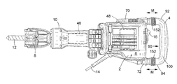
- FIG. 1 shows a sketch of a side view of a hammer drill embodying the present invention
- FIG. 2 shows a vertical cross section of a rear handle assembly of the hammer drill of FIG. 1 when a handle therefore is biased away from a body thereof by the maximum amount;
- FIG. 3 shows a vertical cross section of the rear handle assembly shown in FIG. 2 when the handle is moved to its closest position to the body against the biasing force of the springs;
- FIG. 4 is a cross section view in the direction of Arrows C in FIG. 3 ;
- FIG. 5 is a cross section view in the direction of Arrows A in FIG. 2 ;
- FIG. 6 is a cross section view in the direction of Arrows B in FIG. 2 ;
- FIG. 7 is a cross section view in the direction of Arrows D in FIG. 2 ;
- FIG. 8 is a perspective view of an insert of the handle assembly of FIG. 2 ;
- FIG. 9A shows a schematic diagram of the insert and tube located within the rear section 128 when no sideways (Arrows E and F) load is exerted on the tube;
- FIG. 9B shows a schematic diagram of one side of insert and tube located within the rear section 128 when the insert is deformed along its length to allow sideways (Arrows E and F) movement of the tube.
- the hammer drill comprises a body 2 having a rear handle 4 moveably mounted to the rear of the body 2 .
- the rear handle 4 comprises a centre grip section 90 and two end connection sections 92 ; 94 , one end connection section being attached to one end of the centre grip section, the other end connection section being connected to the other end of the centre grip section.
- the handle 4 is connected to the rear of the body 2 by the two end connection sections 92 , 94 .
- the rear handle is constructed from a plastic clam shell 100 .
- the rear of the body is formed by three plastic clam shells 6 , 70 , 72 which attach to each other and to the remainder of the body 2 using screws (not shown).
- a tool holder 8 is mounted onto the front 10 of the body 2 .
- the tool holder can hold a cutting tool 12 , such as a drill bit.
- a motor (shown generally by dashed lines 48 ) is mounted within the body 2 which is powered by a mains electricity supply via a cable 14 .
- a switch 16 is mounted on the rear handle 4 . Depression of the switch 16 activates the motor in the normal manner.
- the motor drives a hammer mechanism (shown generally by dashed lines 46 ), which comprises a ram (not shown) reciprocatingly driven by the motor within a cylinder (not shown) which in turn strikes, via a beat piece (not shown), the end of the cutting tool 12 .
- the rear handle 4 can move in the direction of Arrow M in FIG. 1 .
- the movement of handle 4 is controlled using two movement control mechanisms, as described below, so that it moves linearly towards or away from the body 2 of the hammer drill, but rotation of the handle 4 relative to the body 2 of the hammer drill is significantly restricted.
- Two helical springs 104 ( FIG. 2 ) bias the rear handle 4 away from the body 2 .
- Each movement control mechanism is identical to the other movement control mechanism. As such, a single description of a movement control mechanism will be provided but is equally applicable to either of the two movement control mechanisms.
- Each movement control mechanism comprises a metal tube 106 of circular cross section and with a smooth outer surface, one end of which located with a correspondingly shaped recess 108 formed in the clam shell 100 of the rear handle 4 .
- a plastic plug 110 comprises an elongate body 112 of circular cross section with a head 114 , having a coffin shaped cross section (see FIG. 5 ), attached to one end.
- the outer diameter of the elongate body 112 is the same as the inner diameter of the tube 106 .
- the head 114 has dimensions which are greater than the inner diameter of the tube 106 .
- the elongate body 112 is slid inside the free end of the tube 106 remote from the handle 4 until the head 114 is located adjacent the free end as shown in the Figures.
- a hole 109 is formed through the base of the recess 108 which extends through to a cut out 118 formed in the rear of the clam shell 100 of the handle 4 .
- a threaded shaft 116 of a bolt passes through a metal washer 120 located in the cut out 118 , through the hole 109 , through the length of the tube 106 and screws into a threaded bore 122 formed in the elongate body 112 of the plug 110 .
- the head 124 of the bolt locates against the washer 120 in the cut out 118 .
- the bolt rigidly secures the plug 110 to the tube 106 and the tube to the clam shell 100 of the rear handle 4 .
- Two of the clam shells 70 , 72 which form the rear of the body 2 each have a recess formed in two sections, a front section 126 and a rear section 128 separated by an annular ridge 130 .
- Each recess forms a part of one of the movement control mechanisms.
- first rigid plastic tubular insert 133 which has a tubular passage within it which is coffin shaped in cross section along its length as shown in FIG. 5 .
- the tubular insert 133 is held in place in the clam shell 70 , 72 by means of a plastic cover 150 which is attached to the clam shell 70 , 72 using screws (not shown).
- the dimensions of the cross sectional shape of the tubular passage correspond to that of the head 114 .
- the head 114 locates inside of the insert 133 and is capable of sliding from the rear end ( FIG. 2 ) of the tubular passage, along the length of the passage, to the front end ( FIG. 3 ).
- platforms 132 along the inside walls of the tubular passage are platforms 132 ( FIG.
- the insert 136 Located in the rear section 128 of each recess is a second rigid plastic tubular insert 136 .
- the insert 136 has a tapering body portion 200 of uniform thickness defining an inner surface 138 of circular cross section.
- the body portion 200 has a pair of slots 202 arranged along the majority of its length and a flange 204 at one end.
- the body portion 200 tapers, in a lengthwise direction, from a narrow cross section 142 at the rear end to a larger cross section 140 at the front end.
- the part of the insert 136 with the smallest cross section area 142 has the same dimensions as that of the outer diameter of the tube 106 and slidingly engages with the smooth outer surface of tube 106 .
- the external dimension of the larger cross section part 140 is the same as the internal dimension of the internal part of the rear section 128 of the recess, such that the insert 136 has an interference fit in the rear section 128 of the recess, and the flange 204 abuts the end of the rear section 128 of the recess such that a small gap 206 is formed between the outer surface of the insert 136 and the inner surface of the rear section 128 of the recess. This allows limited movement of the insert 136 relative to the rear section 128 of the recess in the direction of arrows E and F in FIGS. 2 and 3 as a result of bending of the insert 136 .
- the part of the insert 136 with the smallest cross section area 142 has the same dimensions as that of the outer diameter of the tube 106 and slidingly engages with the smooth outer surface of tube 106 , this ensures that the only part of the insert 136 which engages the tube is the rear part 142 . As such, a flush contact is made between the insert 136 and the side of the tube 106 at a single point along the length of the tube.
- the only connection between the tube 106 and the body 2 is at two points only along the length of the tune 106 .
- the connection points are formed via the inserts 133 , 136 .
- the first connection point is via the side of the head 114 engaging with the platforms 132 on the inner walls of the first tubular insert 133 .
- the second connection point is via the side of the tube 106 engaging the part 142 of the second tubular insert 136 having the smallest cross section. In between these two points, there is no contact between the tube 106 and the inserts 133 , 136 or the clam shells 70 , 72 .
- Such a construction ensures that the movement of the handle 4 is almost entirely linear, in a direction parallel to the longitudinal axis 107 of the tube 106 , with limited sideways movement of the handle 4 in the direction of Arrows E or F.
- the handle 4 is largely prevented from rotation about the longitudinal axis 107 of either of the tubes 106 of the two movement control mechanisms. As such, the movement of the handle 4 is almost totally linear with only limited rotation relative to the body 2 .
- a helical spring 104 Sandwiched between the clam shell 100 of the handle 4 and the clam shell 70 , 72 of the body 2 and surrounding the tube 106 is a helical spring 104 .
- the helical spring biases the handle away from the body 2 .
- the springs of the two movement control mechanisms absorb vibration from the body 2 , reducing the amount transferred from the body 2 to the handle 4 .
- Bellows 152 surround the spring 104 and the tube 106 and connect between the clam shell 100 of the handle 4 and the clam shell 70 , 72 of the rear of the body 2 to prevent the ingress of dust during use of the hammer.
- a resilient cushion 144 Located inside the first tubular insert 133 at the forward end of the tubular passage is a resilient cushion 144 made of rubber material.
- the handle 4 When the handle 4 is pushed towards the body 2 to its inner most position (see FIG. 3 ), the head 114 engages with the cushion 144 , preventing the head 114 from moving further forward.
- the cushion 144 also damps any vibration which would otherwise be transmitted from the insert to the head 144 .
- the recess 108 and the hole 109 for the two movement control mechanisms are circular in cross section. This ensures that the position of the tube 106 and/or the shaft 116 of the bolt, in a direction perpendicular to their longitudinal axes 107 , relative to the clam shell 100 of the handle 4 is fixed.
- the recess 108 ′ and the and the hole 109 ′ of the lower movement control mechanism as viewed in FIG. 2 are oval in cross section, with the longer axis of the oval being vertical (a small gap is visible in FIG. 2 ).
- the oval recess 108 ′ and hole 109 ′ allow the tube 106 and the bolt of the lower movement control mechanism to locate in positions within the recess 108 ′ and hole 109 ′ where there are no bending stress (in the direction of Arrows E or F) on the tube 106 and bolt. This in turn prevents there being any bending stresses (in the direction of Arrows E or F) on the tube 106 and bolt of the top movement control mechanism.
- the handle When the hammer drill is not being used, the handle is biased away from the body 2 under the influence of the two helical springs 104 to the position shown in FIG. 2 . In this position, the heads 114 of the plugs 110 are located at the rear most position of the first tubular inserts 133 .
- Each tube 106 is supported at two points, namely, the point where the part 142 of the second tubular insert 136 having the smallest cross section engages the side of the tube 106 and the point where the head 114 of the plug 110 engages the inner walls of the rear most part of the tubular passage of the first tubular insert 133 .
- the distance between these two points is L 1 .
- each tube 106 slides axially into the body 2 .
- the head 114 of each plug 110 slides forward inside of the first tubular insert 133 towards the cushion 144 .
- each tube 106 slides through the second tubular insert 136 , the part 142 of the second tubular insert 136 having the smallest cross section sliding along the side of the tube 106 as it does so.
- the two movement control mechanism operate in unison.
- the platforms 132 on the inner wall of the first tubular insert which provide a defined contact area between the insert 133 and head 114 along which the head 114 slides, enables relative sliding action between the head and the insert 133 to be smooth and prevents the head from jamming inside of the first tubular insert 133 .
- any vibration generated by the operation of the hammer is damped by the helical springs 104 .
- the distance between the two points namely, the point where the part 142 of the second tubular insert 136 having the smallest cross section engages the side of the tube 106 and the point where the head 114 of the plug 110 engages the inner wall of the rear most part of the tubular passage of the first tubular insert 133 , increases.
- the head 114 of the plug 110 When the operator has applied the maximum pressure to the handle 4 , the head 114 of the plug 110 is located at the fore most position of the first tubular insert 133 adjacent the cushion 144 as shown in FIG. 3 . The distance between these two support points is L 2 . The head 114 engages with the cushion is prevented from moving any further inside of the first tubular insert 133 .
- the distance L 2 is greater than L 1 .
- This has the advantage that, as the pressure applied by the operator on the handle during use increases, the distance between the support points along the length of the tube 106 increases, providing an increasing amount of support to the tube 106 against bending forces (in the direction of Arrows E or F). As such, it provides a wider support structure to the tube 106 .
- the two support points are the maximum distance part, providing the greatest support to the tube 106 against bending.
- an insert 136 which is tapered along the length of its body 200 and is able to bend sideways within the rear section 128 allows limited sideways movement of the tube 106 within the rear section thus providing some vibration dampening in the direction of Arrows E and F.
Landscapes
- Engineering & Computer Science (AREA)
- Mechanical Engineering (AREA)
- Percussive Tools And Related Accessories (AREA)
Applications Claiming Priority (2)
| Application Number | Priority Date | Filing Date | Title |
|---|---|---|---|
| GB1112833.7 | 2011-07-26 | ||
| GBGB1112833.7A GB201112833D0 (en) | 2011-07-26 | 2011-07-26 | A hammer drill |
Publications (2)
| Publication Number | Publication Date |
|---|---|
| US20130025897A1 US20130025897A1 (en) | 2013-01-31 |
| US9168649B2 true US9168649B2 (en) | 2015-10-27 |
Family
ID=44652333
Family Applications (1)
| Application Number | Title | Priority Date | Filing Date |
|---|---|---|---|
| US13/555,489 Active 2034-02-25 US9168649B2 (en) | 2011-07-26 | 2012-07-23 | Hammer drill |
Country Status (3)
| Country | Link |
|---|---|
| US (1) | US9168649B2 (fr) |
| EP (1) | EP2551061B1 (fr) |
| GB (1) | GB201112833D0 (fr) |
Cited By (5)
| Publication number | Priority date | Publication date | Assignee | Title |
|---|---|---|---|---|
| US20140262402A1 (en) * | 2013-03-14 | 2014-09-18 | Robert Bosch Gmbh | Power Hand Tool with Vibration Isolation |
| US20140326475A1 (en) * | 2013-05-06 | 2014-11-06 | Hilti Aktiengesellschaft | Hand-held power tool |
| US20220266433A1 (en) * | 2021-02-22 | 2022-08-25 | Makita Corporation | Power tool having a hammer mechanism |
| US20220266432A1 (en) * | 2021-02-22 | 2022-08-25 | Makita Corporation | Power tool having a hammer mechanism |
| US11759938B2 (en) | 2021-10-19 | 2023-09-19 | Makita Corporation | Impact tool |
Families Citing this family (14)
| Publication number | Priority date | Publication date | Assignee | Title |
|---|---|---|---|---|
| GB201112825D0 (en) * | 2011-07-26 | 2011-09-07 | Black & Decker Inc | A hammer drill |
| US9849577B2 (en) | 2012-02-03 | 2017-12-26 | Milwaukee Electric Tool Corporation | Rotary hammer |
| JP6070945B2 (ja) * | 2013-05-28 | 2017-02-01 | 日立工機株式会社 | 携帯型作業機 |
| EP3022019B2 (fr) * | 2013-07-15 | 2025-08-06 | Milwaukee Electric Tool Corporation | Perceuse à percussion |
| JP6125392B2 (ja) * | 2013-09-27 | 2017-05-10 | 株式会社マキタ | 打撃工具 |
| EP2898991B1 (fr) | 2014-01-23 | 2018-12-26 | Black & Decker Inc. | Poignée arrière |
| EP2898992B1 (fr) | 2014-01-23 | 2016-05-04 | Black & Decker Inc. | Outil électrique avec poignée arrière, méthode d'assemblage d'une partie d'une poignée pour un outil électrique et méthode de démontage d'une partie d'une poignée pour un outil électrique |
| EP2898994A1 (fr) | 2014-01-23 | 2015-07-29 | Black & Decker Inc. | Outil électrique avec une poignée arrière |
| EP2898993B1 (fr) | 2014-01-23 | 2019-01-30 | Black & Decker Inc. | Outil electrique |
| JP6703417B2 (ja) * | 2016-02-19 | 2020-06-03 | 株式会社マキタ | 作業工具 |
| CN108326803A (zh) * | 2017-12-30 | 2018-07-27 | 天津市九方煤矿机械制造有限公司 | 一种手持式凿岩机 |
| US11274400B2 (en) * | 2018-07-25 | 2022-03-15 | Robel Bahnbaumaschinen Gmbh | Nail punching machine for driving in or pulling out rail spikes of a rail track |
| US20220055198A1 (en) * | 2020-08-24 | 2022-02-24 | Makita Corporation | Power tool having hammer mechanism |
| JP7796602B2 (ja) * | 2022-07-14 | 2026-01-09 | 株式会社マキタ | 打撃工具 |
Citations (41)
| Publication number | Priority date | Publication date | Assignee | Title |
|---|---|---|---|---|
| US3637029A (en) * | 1970-09-14 | 1972-01-25 | Textron Inc | Hand-held power tool with antivibration mount |
| US4478293A (en) * | 1981-06-10 | 1984-10-23 | Hilti Aktiengesellschaft | Hammer drill or chipping hammer |
| US4749049A (en) * | 1983-04-02 | 1988-06-07 | Wacker-Werke Gmbh & Co. Kg | Hand-guided impact hammer and hammer drill |
| US5375666A (en) * | 1993-07-23 | 1994-12-27 | Ryobi Outdoor Products | Vibration isolator for a portable power tool |
| US5692574A (en) * | 1994-07-12 | 1997-12-02 | Makita Corporation | Vibrating tool and a vibration isolating ring |
| US5697456A (en) * | 1995-04-10 | 1997-12-16 | Milwaukee Electric Tool Corp. | Power tool with vibration isolated handle |
| US6076616A (en) * | 1996-11-12 | 2000-06-20 | Wacker-Werke Gmbh & Co. Kg | Working tool which can be guided in a grab handle |
| US6148930A (en) | 1997-01-02 | 2000-11-21 | Wacker-Werke Gmbh & Co. Kg | Percussion drill and/or jack hammer with handle spring-buffered against the hammer housing |
| US6286610B1 (en) * | 1997-07-15 | 2001-09-11 | Wacker-Werke Gmbh & Co. Kg | Percussion and/or drill hammer with oscillation damping |
| US6309183B1 (en) * | 1997-05-05 | 2001-10-30 | King Of Fans, Inc. | Blade arm |
| EP1157788A2 (fr) | 2000-04-07 | 2001-11-28 | Black & Decker Inc. | Mécanisme de changement de mode de fonctionnement pour marteau rotatif |
| US6863499B2 (en) * | 2002-07-12 | 2005-03-08 | Hunter Fan Company | Quick connect blade iron system |
| US20050095135A1 (en) * | 1997-05-05 | 2005-05-05 | King Of Fans, Inc., A Corporation | Quick install blade arms for ceiling fans |
| EP1529603A2 (fr) | 2003-11-04 | 2005-05-11 | BLACK & DECKER INC. | Système limitant les vibrations pour outil électrique, et outil incorporant ce système |
| US6935842B2 (en) * | 2003-12-05 | 2005-08-30 | Chun Ya Tai | Ceiling fan blade mounting assembly for ceiling fan |
| US20050224244A1 (en) * | 2000-06-15 | 2005-10-13 | Ernst Kraenzler | Hand machine tool comprising at least one handle |
| US20060086515A1 (en) * | 2004-10-22 | 2006-04-27 | Uwe Engelfried | Hand power tool with vibration-damped pistol grip |
| US20060113098A1 (en) * | 2004-10-29 | 2006-06-01 | Hiroto Inagawa | Power tool |
| US20060219418A1 (en) * | 2005-03-29 | 2006-10-05 | Makita Corporation | Reciprocating power tool |
| US20060289183A1 (en) * | 2005-06-24 | 2006-12-28 | Alfred Schreiber | Hand-held power tool with damping system |
| US20070212990A1 (en) * | 2006-03-10 | 2007-09-13 | Kuragano Shinji | Power tool |
| US20070289762A1 (en) * | 2006-06-16 | 2007-12-20 | Kikukchi Atsuyuki | Power tool |
| US20070295521A1 (en) * | 2006-06-16 | 2007-12-27 | Juergen Wiker | Hand power tool |
| US20080022817A1 (en) | 2006-07-27 | 2008-01-31 | Axel Fischer | Hand-held power tool with a decoupling device |
| EP2018938A1 (fr) | 2007-07-27 | 2009-01-28 | Black & Decker, Inc. | Poignée de marteau |
| EP2082845A2 (fr) | 2008-01-24 | 2009-07-29 | Black & Decker, Inc. | Ensemble de montage pour poignée d'outil électrique |
| US7591325B2 (en) * | 2007-01-10 | 2009-09-22 | Aeg Electric Tools Gmbh | Portable hand-guided power tool |
| US20090266571A1 (en) * | 2005-12-12 | 2009-10-29 | Otto Baumann | Hand-guided power tool with a power train and a decoupling device |
| US20090294144A1 (en) * | 2005-02-18 | 2009-12-03 | Karl Frauhammer | Hand-held power tool |
| US20100012339A1 (en) * | 2006-03-03 | 2010-01-21 | Black And Decker Inc. | Handle damping system |
| US20100186979A1 (en) * | 2007-06-20 | 2010-07-29 | Jochen Krauter | Machine hand tool housing unit |
| US20100193210A1 (en) * | 2007-07-02 | 2010-08-05 | Jochen Krauter | Elastic connection between housing parts of motor-driven power tools |
| US20100193209A1 (en) * | 2008-01-25 | 2010-08-05 | Joachim Schadow | Hand-held power tool, in particular electrically driven hand-held power tool |
| US20100206596A1 (en) * | 2007-09-18 | 2010-08-19 | Makita Corporation | Hand-held power tool |
| US7850055B2 (en) * | 2007-03-15 | 2010-12-14 | Black & Decker Inc. | Assembly having gasket resistant to side loading by pressurized fluid |
| US20110011608A1 (en) * | 2005-10-04 | 2011-01-20 | Dietmar Saur | Power tool |
| EP2289669A1 (fr) | 2009-08-26 | 2011-03-02 | Black & Decker Inc. | Marteau perforateur |
| US7921935B2 (en) * | 2006-04-07 | 2011-04-12 | Robert Bosch Gmbh | Handheld power tool with vibration-damped handle |
| US7967079B2 (en) * | 2005-04-11 | 2011-06-28 | Robert Bosch Gmbh | Hand-held power tool |
| US8061438B2 (en) * | 2006-05-08 | 2011-11-22 | Robert Bosch Gmbh | Hand-held power tool with a vibration-damped handle |
| US20120031639A1 (en) * | 2010-08-05 | 2012-02-09 | Black And Decker Inc. | Rear handle |
Family Cites Families (2)
| Publication number | Priority date | Publication date | Assignee | Title |
|---|---|---|---|---|
| US4865997A (en) | 1984-02-23 | 1989-09-12 | Becton Dickinson And Company | Assay for ligands by separating bound and free tracer from sample |
| US9061365B2 (en) | 2007-07-23 | 2015-06-23 | Daihen Corporation | Pulse arc welding method |
-
2011
- 2011-07-26 GB GBGB1112833.7A patent/GB201112833D0/en not_active Ceased
-
2012
- 2012-07-19 EP EP12177141.4A patent/EP2551061B1/fr active Active
- 2012-07-23 US US13/555,489 patent/US9168649B2/en active Active
Patent Citations (43)
| Publication number | Priority date | Publication date | Assignee | Title |
|---|---|---|---|---|
| US3637029A (en) * | 1970-09-14 | 1972-01-25 | Textron Inc | Hand-held power tool with antivibration mount |
| US4478293A (en) * | 1981-06-10 | 1984-10-23 | Hilti Aktiengesellschaft | Hammer drill or chipping hammer |
| US4749049A (en) * | 1983-04-02 | 1988-06-07 | Wacker-Werke Gmbh & Co. Kg | Hand-guided impact hammer and hammer drill |
| US5375666A (en) * | 1993-07-23 | 1994-12-27 | Ryobi Outdoor Products | Vibration isolator for a portable power tool |
| US5692574A (en) * | 1994-07-12 | 1997-12-02 | Makita Corporation | Vibrating tool and a vibration isolating ring |
| US5697456A (en) * | 1995-04-10 | 1997-12-16 | Milwaukee Electric Tool Corp. | Power tool with vibration isolated handle |
| US6076616A (en) * | 1996-11-12 | 2000-06-20 | Wacker-Werke Gmbh & Co. Kg | Working tool which can be guided in a grab handle |
| US6148930A (en) | 1997-01-02 | 2000-11-21 | Wacker-Werke Gmbh & Co. Kg | Percussion drill and/or jack hammer with handle spring-buffered against the hammer housing |
| US20050095135A1 (en) * | 1997-05-05 | 2005-05-05 | King Of Fans, Inc., A Corporation | Quick install blade arms for ceiling fans |
| US6309183B1 (en) * | 1997-05-05 | 2001-10-30 | King Of Fans, Inc. | Blade arm |
| US6286610B1 (en) * | 1997-07-15 | 2001-09-11 | Wacker-Werke Gmbh & Co. Kg | Percussion and/or drill hammer with oscillation damping |
| EP1157788A2 (fr) | 2000-04-07 | 2001-11-28 | Black & Decker Inc. | Mécanisme de changement de mode de fonctionnement pour marteau rotatif |
| US20050224244A1 (en) * | 2000-06-15 | 2005-10-13 | Ernst Kraenzler | Hand machine tool comprising at least one handle |
| US6863499B2 (en) * | 2002-07-12 | 2005-03-08 | Hunter Fan Company | Quick connect blade iron system |
| EP1529603A2 (fr) | 2003-11-04 | 2005-05-11 | BLACK & DECKER INC. | Système limitant les vibrations pour outil électrique, et outil incorporant ce système |
| US6935842B2 (en) * | 2003-12-05 | 2005-08-30 | Chun Ya Tai | Ceiling fan blade mounting assembly for ceiling fan |
| US8069930B2 (en) * | 2004-10-22 | 2011-12-06 | Robert Bosch Gmbh | Hand power tool with vibration-damped pistol grip |
| US20060086515A1 (en) * | 2004-10-22 | 2006-04-27 | Uwe Engelfried | Hand power tool with vibration-damped pistol grip |
| US20060113098A1 (en) * | 2004-10-29 | 2006-06-01 | Hiroto Inagawa | Power tool |
| US20090294144A1 (en) * | 2005-02-18 | 2009-12-03 | Karl Frauhammer | Hand-held power tool |
| US20060219418A1 (en) * | 2005-03-29 | 2006-10-05 | Makita Corporation | Reciprocating power tool |
| US7967079B2 (en) * | 2005-04-11 | 2011-06-28 | Robert Bosch Gmbh | Hand-held power tool |
| US20060289183A1 (en) * | 2005-06-24 | 2006-12-28 | Alfred Schreiber | Hand-held power tool with damping system |
| US20110011608A1 (en) * | 2005-10-04 | 2011-01-20 | Dietmar Saur | Power tool |
| US20090266571A1 (en) * | 2005-12-12 | 2009-10-29 | Otto Baumann | Hand-guided power tool with a power train and a decoupling device |
| US20100012339A1 (en) * | 2006-03-03 | 2010-01-21 | Black And Decker Inc. | Handle damping system |
| US20070212990A1 (en) * | 2006-03-10 | 2007-09-13 | Kuragano Shinji | Power tool |
| US7921935B2 (en) * | 2006-04-07 | 2011-04-12 | Robert Bosch Gmbh | Handheld power tool with vibration-damped handle |
| US8061438B2 (en) * | 2006-05-08 | 2011-11-22 | Robert Bosch Gmbh | Hand-held power tool with a vibration-damped handle |
| US20070289762A1 (en) * | 2006-06-16 | 2007-12-20 | Kikukchi Atsuyuki | Power tool |
| US20070295521A1 (en) * | 2006-06-16 | 2007-12-27 | Juergen Wiker | Hand power tool |
| US20080022817A1 (en) | 2006-07-27 | 2008-01-31 | Axel Fischer | Hand-held power tool with a decoupling device |
| US7591325B2 (en) * | 2007-01-10 | 2009-09-22 | Aeg Electric Tools Gmbh | Portable hand-guided power tool |
| US7850055B2 (en) * | 2007-03-15 | 2010-12-14 | Black & Decker Inc. | Assembly having gasket resistant to side loading by pressurized fluid |
| US20100186979A1 (en) * | 2007-06-20 | 2010-07-29 | Jochen Krauter | Machine hand tool housing unit |
| US20100193210A1 (en) * | 2007-07-02 | 2010-08-05 | Jochen Krauter | Elastic connection between housing parts of motor-driven power tools |
| EP2018938A1 (fr) | 2007-07-27 | 2009-01-28 | Black & Decker, Inc. | Poignée de marteau |
| US20100206596A1 (en) * | 2007-09-18 | 2010-08-19 | Makita Corporation | Hand-held power tool |
| US8240395B2 (en) * | 2007-09-18 | 2012-08-14 | Makita Corporation | Hand-held power tool |
| EP2082845A2 (fr) | 2008-01-24 | 2009-07-29 | Black & Decker, Inc. | Ensemble de montage pour poignée d'outil électrique |
| US20100193209A1 (en) * | 2008-01-25 | 2010-08-05 | Joachim Schadow | Hand-held power tool, in particular electrically driven hand-held power tool |
| EP2289669A1 (fr) | 2009-08-26 | 2011-03-02 | Black & Decker Inc. | Marteau perforateur |
| US20120031639A1 (en) * | 2010-08-05 | 2012-02-09 | Black And Decker Inc. | Rear handle |
Cited By (9)
| Publication number | Priority date | Publication date | Assignee | Title |
|---|---|---|---|---|
| US20140262402A1 (en) * | 2013-03-14 | 2014-09-18 | Robert Bosch Gmbh | Power Hand Tool with Vibration Isolation |
| US20140326475A1 (en) * | 2013-05-06 | 2014-11-06 | Hilti Aktiengesellschaft | Hand-held power tool |
| US10710230B2 (en) * | 2013-05-06 | 2020-07-14 | Hilti Aktiengesellschaft | Hand-held power tool with detachable clamped connection |
| US20220266433A1 (en) * | 2021-02-22 | 2022-08-25 | Makita Corporation | Power tool having a hammer mechanism |
| US20220266432A1 (en) * | 2021-02-22 | 2022-08-25 | Makita Corporation | Power tool having a hammer mechanism |
| US11642769B2 (en) * | 2021-02-22 | 2023-05-09 | Makita Corporation | Power tool having a hammer mechanism |
| US12246427B2 (en) * | 2021-02-22 | 2025-03-11 | Makita Corporation | Power tool having a hammer mechanism |
| US11759938B2 (en) | 2021-10-19 | 2023-09-19 | Makita Corporation | Impact tool |
| US11919138B2 (en) * | 2021-10-19 | 2024-03-05 | Makita Corporation | Impact tool |
Also Published As
| Publication number | Publication date |
|---|---|
| EP2551061B1 (fr) | 2016-12-21 |
| US20130025897A1 (en) | 2013-01-31 |
| GB201112833D0 (en) | 2011-09-07 |
| EP2551061A1 (fr) | 2013-01-30 |
Similar Documents
| Publication | Publication Date | Title |
|---|---|---|
| US9168649B2 (en) | Hammer drill | |
| US8584769B2 (en) | Vibration reduction handle assembly for a hammer drill | |
| EP2551060B1 (fr) | Outil électrique | |
| JP5361504B2 (ja) | 打撃工具 | |
| US9950415B2 (en) | Impact tool | |
| US8939231B2 (en) | Rear handle | |
| EP1529603B1 (fr) | Système limitant les vibrations pour outil électrique, et outil incorporant ce système | |
| US8708059B2 (en) | Mounting assembly for handle for power tool | |
| US8234756B2 (en) | Handle for power tool | |
| US10406668B2 (en) | Handheld power tool | |
| EP2898994A1 (fr) | Outil électrique avec une poignée arrière | |
| CN100340376C (zh) | 用于动力工具的减振装置和含有这种装置的动力工具 | |
| JP7060098B2 (ja) | 電動工具 | |
| US7472760B2 (en) | Vibration reduction apparatus for power tool and power tool incorporating such apparatus | |
| JP7365197B2 (ja) | 往復動工具 | |
| WO2023024021A1 (fr) | Outil électrique doté de structures antivibrations | |
| SE545906C2 (en) | Hand-held percussive tool | |
| JP2014166670A (ja) | 打撃工具 |
Legal Events
| Date | Code | Title | Description |
|---|---|---|---|
| AS | Assignment |
Owner name: BLACK & DECKER INC., MARYLAND Free format text: ASSIGNMENT OF ASSIGNORS INTEREST;ASSIGNORS:FRIEDRICH, ANDREAS;HARCAR, FRANTISEK;SIGNING DATES FROM 20121108 TO 20121123;REEL/FRAME:029353/0588 |
|
| STCF | Information on status: patent grant |
Free format text: PATENTED CASE |
|
| MAFP | Maintenance fee payment |
Free format text: PAYMENT OF MAINTENANCE FEE, 4TH YEAR, LARGE ENTITY (ORIGINAL EVENT CODE: M1551); ENTITY STATUS OF PATENT OWNER: LARGE ENTITY Year of fee payment: 4 |
|
| MAFP | Maintenance fee payment |
Free format text: PAYMENT OF MAINTENANCE FEE, 8TH YEAR, LARGE ENTITY (ORIGINAL EVENT CODE: M1552); ENTITY STATUS OF PATENT OWNER: LARGE ENTITY Year of fee payment: 8 |