US9181757B2 - Sucker rod apparatus and method - Google Patents
Sucker rod apparatus and method Download PDFInfo
- Publication number
- US9181757B2 US9181757B2 US13/385,410 US201213385410A US9181757B2 US 9181757 B2 US9181757 B2 US 9181757B2 US 201213385410 A US201213385410 A US 201213385410A US 9181757 B2 US9181757 B2 US 9181757B2
- Authority
- US
- United States
- Prior art keywords
- wedge shaped
- shaped portion
- wedge
- leading edge
- trailing edge
- Prior art date
- Legal status (The legal status is an assumption and is not a legal conclusion. Google has not performed a legal analysis and makes no representation as to the accuracy of the status listed.)
- Active, expires
Links
- 238000000034 method Methods 0.000 title claims description 44
- 239000002131 composite material Substances 0.000 claims description 114
- 239000000835 fiber Substances 0.000 claims description 113
- 238000004519 manufacturing process Methods 0.000 claims description 32
- 239000004593 Epoxy Substances 0.000 claims description 23
- 230000003247 decreasing effect Effects 0.000 claims description 16
- 239000011800 void material Substances 0.000 claims description 11
- 230000008878 coupling Effects 0.000 claims description 6
- 238000010168 coupling process Methods 0.000 claims description 6
- 238000005859 coupling reaction Methods 0.000 claims description 6
- 230000007423 decrease Effects 0.000 claims description 6
- 230000011514 reflex Effects 0.000 claims description 6
- 230000006835 compression Effects 0.000 claims 6
- 238000007906 compression Methods 0.000 claims 6
- 230000001154 acute effect Effects 0.000 claims 2
- 239000011152 fibreglass Substances 0.000 abstract description 7
- 238000005086 pumping Methods 0.000 description 14
- 239000000463 material Substances 0.000 description 7
- 229910000831 Steel Inorganic materials 0.000 description 6
- 239000000853 adhesive Substances 0.000 description 6
- 230000001070 adhesive effect Effects 0.000 description 6
- 239000010959 steel Substances 0.000 description 6
- 230000008859 change Effects 0.000 description 5
- 238000012546 transfer Methods 0.000 description 4
- 239000003129 oil well Substances 0.000 description 3
- 238000013461 design Methods 0.000 description 2
- 229920001971 elastomer Polymers 0.000 description 2
- 239000012530 fluid Substances 0.000 description 2
- 230000004048 modification Effects 0.000 description 2
- 238000012986 modification Methods 0.000 description 2
- 239000004033 plastic Substances 0.000 description 2
- 239000000126 substance Substances 0.000 description 2
- 230000005483 Hooke's law Effects 0.000 description 1
- 230000004075 alteration Effects 0.000 description 1
- 230000003466 anti-cipated effect Effects 0.000 description 1
- 239000012141 concentrate Substances 0.000 description 1
- 230000001419 dependent effect Effects 0.000 description 1
- 238000011161 development Methods 0.000 description 1
- 230000000694 effects Effects 0.000 description 1
- 239000000806 elastomer Substances 0.000 description 1
- 238000005516 engineering process Methods 0.000 description 1
- 238000005242 forging Methods 0.000 description 1
- 238000005259 measurement Methods 0.000 description 1
- 239000002184 metal Substances 0.000 description 1
- 239000003208 petroleum Substances 0.000 description 1
- 238000003825 pressing Methods 0.000 description 1
- 230000002441 reversible effect Effects 0.000 description 1
- 238000005096 rolling process Methods 0.000 description 1
Images



Classifications
-
- E—FIXED CONSTRUCTIONS
- E21—EARTH OR ROCK DRILLING; MINING
- E21B—EARTH OR ROCK DRILLING; OBTAINING OIL, GAS, WATER, SOLUBLE OR MELTABLE MATERIALS OR A SLURRY OF MINERALS FROM WELLS
- E21B17/00—Drilling rods or pipes; Flexible drill strings; Kellies; Drill collars; Sucker rods; Cables; Casings; Tubings
- E21B17/02—Couplings; joints
- E21B17/04—Couplings; joints between rod or the like and bit or between rod and rod or the like
-
- E—FIXED CONSTRUCTIONS
- E21—EARTH OR ROCK DRILLING; MINING
- E21B—EARTH OR ROCK DRILLING; OBTAINING OIL, GAS, WATER, SOLUBLE OR MELTABLE MATERIALS OR A SLURRY OF MINERALS FROM WELLS
- E21B17/00—Drilling rods or pipes; Flexible drill strings; Kellies; Drill collars; Sucker rods; Cables; Casings; Tubings
- E21B17/10—Wear protectors; Centralising devices, e.g. stabilisers
- E21B17/1071—Wear protectors; Centralising devices, e.g. stabilisers specially adapted for pump rods, e.g. sucker rods
-
- E—FIXED CONSTRUCTIONS
- E21—EARTH OR ROCK DRILLING; MINING
- E21B—EARTH OR ROCK DRILLING; OBTAINING OIL, GAS, WATER, SOLUBLE OR MELTABLE MATERIALS OR A SLURRY OF MINERALS FROM WELLS
- E21B43/00—Methods or apparatus for obtaining oil, gas, water, soluble or meltable materials or a slurry of minerals from wells
- E21B43/12—Methods or apparatus for controlling the flow of the obtained fluid to or in wells
- E21B43/121—Lifting well fluids
- E21B43/126—Adaptations of down-hole pump systems powered by drives outside the borehole, e.g. by a rotary or oscillating drive
- E21B43/127—Adaptations of walking-beam pump systems
-
- F—MECHANICAL ENGINEERING; LIGHTING; HEATING; WEAPONS; BLASTING
- F16—ENGINEERING ELEMENTS AND UNITS; GENERAL MEASURES FOR PRODUCING AND MAINTAINING EFFECTIVE FUNCTIONING OF MACHINES OR INSTALLATIONS; THERMAL INSULATION IN GENERAL
- F16B—DEVICES FOR FASTENING OR SECURING CONSTRUCTIONAL ELEMENTS OR MACHINE PARTS TOGETHER, e.g. NAILS, BOLTS, CIRCLIPS, CLAMPS, CLIPS OR WEDGES; JOINTS OR JOINTING
- F16B2200/00—Constructional details of connections not covered for in other groups of this subclass
- F16B2200/10—Details of socket shapes
-
- Y—GENERAL TAGGING OF NEW TECHNOLOGICAL DEVELOPMENTS; GENERAL TAGGING OF CROSS-SECTIONAL TECHNOLOGIES SPANNING OVER SEVERAL SECTIONS OF THE IPC; TECHNICAL SUBJECTS COVERED BY FORMER USPC CROSS-REFERENCE ART COLLECTIONS [XRACs] AND DIGESTS
- Y10—TECHNICAL SUBJECTS COVERED BY FORMER USPC
- Y10T—TECHNICAL SUBJECTS COVERED BY FORMER US CLASSIFICATION
- Y10T403/00—Joints and connections
- Y10T403/47—Molded joint
-
- Y—GENERAL TAGGING OF NEW TECHNOLOGICAL DEVELOPMENTS; GENERAL TAGGING OF CROSS-SECTIONAL TECHNOLOGIES SPANNING OVER SEVERAL SECTIONS OF THE IPC; TECHNICAL SUBJECTS COVERED BY FORMER USPC CROSS-REFERENCE ART COLLECTIONS [XRACs] AND DIGESTS
- Y10—TECHNICAL SUBJECTS COVERED BY FORMER USPC
- Y10T—TECHNICAL SUBJECTS COVERED BY FORMER US CLASSIFICATION
- Y10T403/00—Joints and connections
- Y10T403/47—Molded joint
- Y10T403/473—Socket or open cup for bonding material
-
- Y10T403/7039—
Definitions
- the present disclosure relates generally to oil well sucker rods.
- the disclosure relates to oil well sucker rods made of fiberglass with end fittings or connectors on each end and the manufacture thereof.
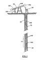
- FIG. 1 illustrates a typical pumping system for use with the technology of the present disclosure.
- FIG. 2 is a cross-sectional view of an embodiment of a sucker rod and an associated end fitting within the scope of the present disclosure.
- FIG. 2A is an exploded view of the blow-up section 2 A as illustrated in FIG. 2 illustrating the angles between the leading edge and the trailing edge of a wedged-shaped portions of the wedge system.
- FIG. 3 is a sectional view of the sucker rod and end fitting combination illustrated in FIG. 2 taken along the section line 3 - 3 .
- FIG. 4 is a sectional view of the sucker rod and end fitting combination illustrated in FIG. 2 taken along the section line 4 - 4 .
- FIG. 5 is a sectional view of the sucker rod and end fitting combination illustrated in FIG. 2 taken along the section line 5 - 5 .
- FIG. 6 is a sectional view of the sucker rod and end fitting combination illustrated in FIG. 2 taken along the section line 6 - 6 .
- FIG. 7 is a sectional view of the sucker rod and end fitting combination illustrated in FIG. 2 taken along the section line 7 - 7 .
- FIG. 8 is a sectional view of the sucker rod and end fitting combination illustrated in FIG. 2 taken along the section line 8 - 8 .
- FIG. 9 is a graph of the relationship between the length on the ordinate of the leading edge and trailing edge of each wedged-shaped portion on the abscissa in the wedge system of the present disclosure.
- FIG. 10 is a cross-sectional view of another embodiment of a sucker rod and an associated end fitting within the scope of the present disclosure.
- FIG. 11 is a sectional view of the sucker rod and end fitting combination illustrated in FIG. 10 taken along the apogee of one of the wedge portions of the wedge system within the scope of the present disclosure.
- FIG. 12 is a sectional view of the sucker rod and end fitting combination illustrated in FIG. 10 taken along the vortex of the wedge portion of the wedge system illustrated in FIG. 11 within the scope of the present disclosure.
- the pressure in the oil reservoir is not sufficient to lift the oil to the surface.
- a pumping unit located at the surface drives the sub-surface pump.
- the pumping unit is connected to the sub-surface pump by a string of sucker rods. The pumping unit moves the sucker rod string up and down to drive the sub-surface pump.
- a sucker rod was a special steel pumping rod.
- a sucker rod is, typically, a steel rod that is used to make up the mechanical assembly between the surface and the down hole components of a rod pumping system.
- Several sucker rods were screwed together to make up the mechanical link, or sucker rod string, from a beam-pumping unit on the surface to the subsurface pump at the bottom of a well.
- the sucker rods were threaded on each end and manufactured to dimension standards and metal specifications set by the petroleum industry.
- sucker rods have been in the lengths of 25 or 30 feet (7.6 or 9.1 meters), and the diameter varies from 1 ⁇ 2 to 11 ⁇ 8 inches (12 to 30 millimeters).
- sucker rod pumping is a method of artificial lift in which a subsurface pump located at or near the bottom of the well and connected to a string of sucker rods is used to lift the well fluid to the surface.
- the weight of the rod string and fluid is counterbalanced by weights attached to a reciprocating beam or to the crank member of a beam-pumping unit or by air pressure in a cylinder attached to the beam.
- sucker rods made of fiberglass with steel connectors are now preferable to use sucker rods made of fiberglass with steel connectors.
- the fiberglass sucker rods provide sufficient strength, and weigh substantially less than steel rods.
- FIG. 1 illustrates a generic pumping system 20 .
- the pumping system 20 includes a pump drive 22 , which is a conventional beam pump, or pump jack and is connected to a down hole pump 26 through a sucker rod string 24 inserted into wellbore 28 .
- the sucker rod string 24 can comprise a continuous sucker rod 10 , which extends from the down hole pump 26 to the pumping system 20 , a series of connected sucker rods 10 , a series of conventional length rods connected together, or any combination thereof.
- the pump drive 22 includes a horsehead 22 A, a beam 22 B, a gearbox 22 c and a motor 22 D.
- the sucker rod 10 is a fiberglass, composite or rod having similar characteristics.
- the sucker rod string 24 may be the same as the continuous sucker rod 10 when the continuous sucker rod 10 is a one-piece rod that extends substantially between the pump drive 22 and the sub-surface pump 26 .
- FIG. 2 is a cross-sectional view of an embodiment of the sucker rod 10 comprising a fiber composite rod 200 and associated end fitting 100 within the scope of the present disclosure.
- the sucker rod 10 comprises one or more end fittings 100 and the fiber composite rod 200 .
- the fiber composite rod 200 has a first end 202 and a second end (not illustrated).
- the end fitting 100 comprises an exterior surface 102 , a closed end 104 , an open end 106 , and an interior surface 108 .
- the interior surface 108 comprises a wedge system 110 .
- the present disclosure provides that the wedge system 110 can have any number of wedges from one to multiple wedges.
- the embodiment illustrated in FIG. 2 has three wedges.
- the wedge system 110 defines a cavity 112 in the end fitting 100 for receiving the fiber composite rod 200 .
- the wedge system 110 comprises a plurality of wedged-shaped portions 114 .
- Each wedged-shaped portion 114 has an apogee 116 , a perigee 124 , a leading edge 118 and a trailing edge 120 extending from and between the apogee 116 and the perigee 124 .
- Each apogee 116 forms a perimeter 122 within the cavity 112 that is the narrowest part of the cavity 112 associated with each wedge shaped portion 114 .
- Each perigee 124 is the widest part of the cavity 112 associated with each wedge shaped portion 114 .
- the leading edge 118 is longer than the trailing edge 120 with the leading edge 118 facing the open end 106 and the trailing edge 120 facing the closed end 104 with respect to each wedge shaped portion 114 of the end fitting 100 .
- the first wedge shaped portion 114 A is proximate to the closed end 104 for receiving compressive forces that are greater than the compressive forces associated with the other wedged-shaped portions 114 B, 114 C. Particularly, the first wedged-shaped portion 114 A receives greater compressive forces than the compressive force for which a second wedge shaped portion 114 B receives that is proximate to the first wedged-shaped portion 114 A.
- a third wedge shaped portion 114 C between the second wedge shaped portion 114 B and the open end 106 receives compressive forces that are less than the compressive forces associated with the first and second wedge shaped portions 114 A, 114 C. Therefore, the compressive forces create a force differential along each wedge shaped portion 114 greater at the closed end 104 of the end fitting 100 and decreasing toward the open end 106 of the end fitting 100 .
- a force transfer continuum is created by the wedge system 110 .
- the force transfer continuum provides for a constant effectiveness between the end fitting 100 and the fiber composite rod 200 as the wedge system 110 deteriorates from one wedged-shaped portion 114 to the next wedged-shaped portion 114 of the wedge system 110 .
- the present structure of the sucker rod 10 including specifically the end fitting 100 does not distribute the compressive forces throughout the end fitting 100 , but rather focuses the compressive forces on each wedge shaped portion 114 of the wedge system 110 of the present disclosure.
- the sucker rod 10 has a plurality of longitudinal cross-sections of the wedged-shaped portions 114 , which forms a plurality of frustro-conical shapes within the cavity 112 .
- the wedge shaped portions 114 of the sucker rod 10 create different compressive forces on each respective edge 118 , 120 thereof with the compressive force being approximately proportional to a length of each edge 118 , 120 .
- the compressive force on each edge 118 , 120 is directly proportional to the length of each edge 118 , 120 .
- the plurality of wedge shaped portions 114 are determined by the angles associated between the leading edge 118 and the trailing edge 120 .
- An adhesive or epoxy 130 is used to sufficiently bond with the fiber composite rod 200 and engage with the end fitting 100 . It is appreciated that any adhesive substance that will sufficiently bond with the fiber composite rod 200 and engage with the end fitting 100 may be used.
- the adhesive or epoxy 130 is placed in the cavity 112 and cured to bond with the fiber composite rod 200 in the cavity 112 for fixedly securing the end fitting 100 with the fiber composite rod 200 .
- FIG. 2A is an exploded view of the blow-up section 2 A as illustrated in FIG. 2 illustrating the angles between the leading edge and the trailing edge of a wedged-shaped portion of the wedge system.
- the angle A between the leading edge 118 and the trailing edge 120 of each wedge shaped portion is obtuse having an angle greater than 90 degrees.
- FIG. 2 illustrates an angle A associated with each wedged-shaped portion 114 of the wedge system 110 .
- FIG. 2A is an exploded view of the blow-up section 2 A as illustrated in FIG. 2 illustrating the angles between the leading edge 118 B and the trailing edge 120 B of a wedged-shaped portion 114 B of the wedge system 110 .
- the fiber composite rod 200 is illustrated in the end fitting 100 .
- the end fitting 100 defines the leading edge 118 B and the trailing edge 120 B to form the cavity 112 to be filled by the epoxy 130 .
- the angle between the leading edge 118 B and the trailing edge 120 B defines the angle A.
- the angle A is obtuse having an angle greater than 90 degrees.
- the leading edge 118 , the trailing edge 120 and the fiber composite rod 200 form a scalene triangle with the longest side of the scalene triangle being along the fiber composite rod 200 , the shortest side of the scalene triangle being along the trailing edge 120 , and the intermediate side of the scalene triangle being along the leading edge 118 .
- FIG. 2A also illustrates the angle B between the trailing edge 120 B of the wedge shaped portion 114 B and the leading edge 118 A of the wedge shaped portion 114 A.
- the angle B defines the relationship between the trailing edge 120 of the wedge shaped portion 114 and the leading edge 118 of an adjacent wedge shaped portion 114 .
- the angle B is a reflex angle.
- a reflex angle is an angle that exceeds 180 degrees.
- FIG. 3 is a sectional view of the fiber composite rod 200 and end fitting 100 combination illustrated in FIG. 2 taken along the section line 3 - 3 .
- the end fitting 100 is exterior of the fiber composite rod 200 with the cavity 112 there between.
- the cavity 112 between the fiber composite rod 200 and the end fitting 100 forms a gap G 3 .
- the gap can be of any dimension, for example, from as small as zero or no gap to as large a gap as required to achieve the efficacy of the present disclosure.
- FIG. 4 is a sectional view of the fiber composite rod 200 and end fitting 100 combination illustrated in FIG. 2 taken along the section line 4 - 4 .
- the end fitting 100 is exterior of the fiber composite rod 200 with the cavity 112 there between.
- the cavity 112 between the fiber composite rod 200 and the end fitting 100 forms a gap G 4 .
- the gaps G 3 and G 4 are associated with the first wedged-shaped portion 114 A of the wedge system 110 .
- FIG. 5 is a sectional view of the fiber composite rod 200 and end fitting 100 combination illustrated in FIG. 2 taken along the section line 5 - 5 .
- the end fitting 100 is exterior of the fiber composite rod 200 with the cavity 112 there between.
- the cavity 112 between the fiber composite rod 200 and the end fitting 100 forms a gap G 5 .
- FIG. 6 is a sectional view of the fiber composite rod 200 and end fitting 100 combination illustrated in FIG. 2 taken along the section line 6 - 6 .
- the end fitting 100 is exterior of the fiber composite rod 200 with the cavity 112 there between.
- the cavity 112 between the fiber composite rod 200 and the end fitting 100 forms a gap G 6 .
- the gaps G 5 and G 6 are associated with the second wedged-shaped portion 114 B of the wedge system 110 .
- FIG. 7 is a sectional view of the fiber composite rod 200 and end fitting 100 combination illustrated in FIG. 2 taken along the section line 7 - 7 .
- the end fitting 100 is exterior of the fiber composite rod 200 with the cavity 112 there between.
- the cavity 112 between the fiber composite rod 200 and the end fitting 100 forms a gap G 7 .
- FIG. 8 is a sectional view of the fiber composite rod 200 and end fitting 100 combination illustrated in FIG. 2 taken along the section line 8 - 8 .
- the end fitting 100 is exterior of the fiber composite rod 200 with the cavity 112 there between.
- the cavity 112 between the fiber composite rod 200 and the end fitting 100 forms a gap G 8 .
- the gaps G 7 and G 8 are associated with the second wedged-shaped portion 114 C of the wedge system 110 .
- FIG. 11 is a sectional view of the sucker rod 10 including the end fitting 100 combination illustrated in FIG. 10 taken along the apogee 116 of one of the wedge portions 114 of the wedge system 110 within the scope of the present disclosure.
- the end fitting 100 is exterior of and engaged with the fiber composite rod 200 with no cavity 112 there between.
- the lack of a cavity 112 between the fiber composite rod 200 and the end fitting 100 forms a zero gap G 9 .
- the gap can be of any dimension, for example, from as small as zero or no gap, as illustrated in FIG. 11 , to as large a gap as required to achieve the efficacy of the present disclosure.
- FIG. 12 is a sectional view of the sucker rod 10 and including the end fitting 100 combination illustrated in FIG. 10 taken along the vortex 124 of the wedge portion 114 of the wedge system 110 illustrated in FIG. 11 within the scope of the present disclosure.
- the end fitting 100 is exterior of the fiber composite rod 200 with the cavity 112 there between.
- the cavity 112 between the fiber composite rod 200 and the end fitting 100 forms a gap G 10 .
- the gap can be of any dimension, for example, from as small as zero or no gap to as large a gap as required to achieve the efficacy of the present disclosure.
- the smaller gaps G 3 , G 5 , G 7 , G 9 associated with each wedged-shaped portion 114 are substantially constant having essentially the same dimension.
- the larger gaps G 4 , G 6 , G 8 , G 10 associated with each wedged-shaped portion 114 are substantially constant having essentially the same dimension.
- the symmetry provided by the relationship of the minimum gaps G 3 , G 5 , G 7 , G 9 and the maximum gaps G 4 , G 6 , G 8 , G 10 provides unforeseen results.
- the symmetry provided by the relationship of the minimum gaps G 3 , G 5 , G 7 , G 9 and the maximum gaps G 4 , G 6 , G 8 , G 10 greatly enhances the stability and ability of the fiber composite rod 200 and end fitting 100 combination to accept enhanced compressive and back pressure forces associated with the reciprocating environment in which the sucker rods 10 are used.
- FIG. 9 is a graph of the relationship between the length on the ordinate (x-axis) of the leading edge 118 and the trailing edge 120 of each wedged-shaped portion 114 on the abscissa (y-axis) in the wedge system 110 of the present disclosure.
- the leading edge 118 is progressively longer from the closed end 104 of the end fitting 100 to the open end 106 of the end fitting 100 .
- the trailing edge 120 is progressively longer from the closed end 104 of the end fitting 100 to the open end 106 of the end fitting 100 .
- the functions defined by these relationships are illustrated in FIG. 9 .
- a line having a slope or gradient defines the function associated with the trailing edge 120
- a line having a slope or gradient defines the function associated with the leading edge 118 .
- the relationship of the function associated with the trailing edge 120 and the function associated with the leading edge 118 provides insight to the unforeseen effectiveness of the wedge system 110 of the present disclosure. It has been found that the rate of increase of the length of the leading edge 118 with respect to the rate of increase of the length of the trailing edge 120 , as defined by the slope or gradient of each associated function, provides an enhanced sucker rod 10 and sucker rod system.
- the slope of the leading edge 118 associated with the wedge system 110 of the present disclosure is greater than the slope of the trailing edge 120 associated with the wedge system 110 of the present disclosure.
- the wedge system 110 of the present disclosure as applied to a sucker rod 10 provides unforeseen effectiveness not before appreciated.
- the combination of the wedged-shaped portions 114 , the relationship of the leading edge 118 to the trailing edge 120 , the symmetry of the minimum gaps G 3 , G 5 , G 7 , G 9 and the maximum gaps G 4 , G 6 , G 8 , G 10 result in a wedge system 110 that provides improved and unpredicted functionality.
- the improved and unpredicted functionality of the sucker rod 10 having the wedge system 110 of the present disclosure greatly enhances the stability of the sucker rod 10 and ability of the fiber composite rod 200 and end fitting 100 combination to accept enhanced compressive and back pressure forces associated with the reciprocating environment in which the sucker rods 10 are used.
- the change of the length of the leading edge increases from the inner wedge to the outer wedge. However, the rate of change of the length of the leading edge is greater than the rate of change of the trailing edge. This is evidenced by the slope of the line for the leading edge 1 and the slope of the line for the trailing edge 2 illustrated in FIG. 9 . For another example, if the slope of the line representing the trailing edge was 1 , then the line would be horizontal in FIG. 9 . Then, the slope of the line representing the leading edge would be any value greater than 1, and would be angled upward from left to right in FIG. 9 .
- the relationship of the rate of change of the lengths of the leading edge to the trailing edge illustrated in FIG. 9 is not described in or anticipated by the prior art.
- the increased rate of change of the length of the leading edge relative to the trailing edge provides enhanced and unexpected characteristics with respect to the effectiveness of the end fitting of the present disclosure.
- the present end fitting design concentrates the compressive forces in the strongest part of the end fitting, the interior wedge.
- there is an increased cohesion between the end fitting and the rod This results in a more secure engagement of the rod within the end fitting.
- this results in reduced strain or deformation as a result of the forces caused by stress associated with the use of the fiberglass rod.
- FIG. 10 is a cross-sectional view of another embodiment of a sucker rod 10 and associated end fitting 100 within the scope of the present disclosure.
- the sucker rod 10 comprises one or more end fittings 100 and a fiber composite rod 200 .
- the fiber composite rod 200 has a first end 202 and a second end (not illustrated).
- the end fitting 100 comprises an exterior surface 102 , a closed end 104 , an open end 106 , and an interior surface 108 .
- the interior surface 108 comprises a wedge system 110 .
- the present disclosure provides that the wedge system 110 can have any number of wedges as indicated by the broken line between the first wedged-shaped portion 114 A and the second wedged-shaped portion 114 B.
- the wedge system 110 defines a cavity 112 in the end fitting 100 .
- the wedge system 110 comprises a plurality of wedged-shaped portions 114 .
- Each wedged-shaped portion 114 has an apogee 116 , a perigee 124 , a leading edge 118 and a trailing edge 120 extending from the apogee 116 and/or the perigee 124 .
- Each apogee 116 forms a perimeter 122 within the cavity 112 that is the narrowest part of the cavity 112 associated with each wedge shaped portion 114 .
- Each perigee 124 forms the widest portion of the cavity 112 associated with each wedge shaped portion 114 .
- the leading edge 118 is longer than the trailing edge 120 with the leading edge 118 facing the open end 106 and the trailing edge 120 facing the closed end 104 with respect to each wedge shaped portion 114 .
- the first wedge shaped portion 114 A is proximate to the closed end 104 for receiving compressive forces that are greater than the compressive forces associated with the other wedged-shaped portions 114 B, C, etc. Particularly, the first wedged-shaped portion 114 A receives greater compressive forces than the compressive forces for which a second wedge shaped portion 114 B receives that is proximate to the first wedged-shaped portion 114 A.
- a third wedge shaped portion 114 C between the second wedge shaped portions 114 B and the open end 106 receives compressive forces that are less than the compressive forces associated with the first and second wedge shaped portions 114 A, 114 C. Therefore, the compressive forces create a force differential along each wedge shaped portion 114 greater at the closed end 104 of the end fitting 100 and decreasing toward the open end 106 of the end fitting 100 .
- a force transfer continuum is created by the wedge system 110 regardless of the number of wedged-shaped portions 114 comprise the wedge system 110 .
- the force transfer continuum provides for a constant effectiveness between the end fitting 100 and the fiber composite rod 200 as the wedge system 110 deteriorates from one wedged-shaped portion 114 to the next wedged-shaped portion 114 of the wedge system 110 .
- the wedge shaped portions 114 of the sucker rod 50 create different compressive forces on each respective edge 118 , 120 thereof with the compressive force being approximately proportional to a length of each edge 118 , 120 .
- the compressive force on each edge 118 , 120 is directly proportional to the length of each edge 118 , 120 .
- the plurality of wedge shaped portions 114 are determined by the angles associated between the leading edge 118 and the trailing edge 120 .
- An adhesive or epoxy 130 is used to sufficiently bond with the fiber composite rod 200 and for engagement with the end fitting 100 . It is appreciated that any adhesive substance that will sufficiently bond with the fiber composite rod 200 and engage with the end fitting 100 may be used.
- the adhesive or epoxy 130 is placed in the cavity 112 and cured to bond with the fiber composite rod 200 in the cavity 112 for fixedly securing the end fitting 100 with the fiber composite rod 200 .
- the angle A between the leading edge 118 and the trailing edge 120 of each wedge shaped portion is obtuse.
- FIG. 2A illustrates an angle A associated with each wedged-shaped portion 114 of the wedge system 110 with respect to the present disclosure.
- FIG. 2A also illustrates the angle B between the trailing edge 120 B of the wedge shaped portion 114 B and the leading edge 118 A of the wedge shaped portion 114 A.
- the angle B defines the relationship between the trailing edge 120 of the wedge shaped portion 114 and the leading edge 118 of an adjacent wedge shaped portion 114 .
- the angle B is a reflex angle.
- a reflex angle is an angle that exceeds 180 degrees.
- the longitudinal cross sections of the concaved portions 110 form frustro-conical shapes.
- the concaved portions 110 create different compressive forces on each respective surface thereof with the compressive force being approximately proportional to the length of each surface.
- the compressive force on each surface increases toward the closed end 104 and decreases toward the open end 106 .
- the compressive force on each first surface 118 is proportional to the length of each surface.
- the compressive force on each second surface 120 is proportional to the length of each second surface.
- the plurality of concaved portions 110 are determined by the angle associated between the first surface 118 and the second surface 120 of each concaved surface 110 .
- the angle between the first surface 118 and the second surface 120 of each concaved surface 110 is obtuse.
- each wedge shape portion 114 may have a length proportional to the compressive force applied to the wedge shape 114 .
- the wedge shape 114 has a length that increases from the closed end 104 to the open end 106 of the end fitting 100 .
- the wedge shaped portions 114 may have a length that decreases from the closed end 104 to the open end 106 of the end fitting 100 .
- a method for manufacturing a sucker rod comprises the steps of constructing an end fitting comprising an exterior surface, a closed end, an open end, and an interior surface.
- the interior surface comprises at least three wedge shaped portions defining a cavity.
- the wedge shaped portions have an apogee and a first and second length extending from the apogee.
- the apogee forms a perimeter that is the narrowest part of the cavity associated with each wedge shaped portion such that the first length is longer than the second length with the first length facing the open end and the second length facing the closed end with respect to each wedge shaped portion.
- the method further comprises engaging an end of a fiber composite rod into the cavity of the end fitting for creating a void between the fiber composite rod and the wedge shaped portions of the end fitting. Thereafter, injecting an epoxy into the void to bond with the fiber composite rod and to fixedly engage the wedge shaped portions of the end fitting for securing the end fitting to the fiber composite rod.
- This arrangement causes the stress to increase the elastic limit without permanent alteration of the fiber composite rod and epoxy combination in the cavity of the end fitting.
- a first wedge shaped portion proximate to the closed end receives compressive forces that are greater than the compressive forces for which a second wedge shaped portion proximate to the open end receives, and an intermediate wedge shaped portion between the first and second wedge shaped portions for receiving compressive forces that are intermediate of the first and second wedge shaped portions.
- the compressive forces create a force differential along the wedge shaped portion greater at the closed end of the fitting and decreasing toward the open end of the fitting.
- the method for manufacturing a sucker rod may further comprise the step of creating different compressive forces on each respective surface of the wedge shaped portions with the compressive force being approximately proportional to the length of each surface.
- the method for manufacturing a sucker rod may comprise the step of the compressive force on each surface increasing toward the closed end and decreasing toward the open end.
- the method for manufacturing a sucker rod may comprise the compressive force on each first surface being proportional to the length of each surface.
- the method for manufacturing a sucker rod may comprise the compressive force on each second surface being proportional to the length of each second surface.
- the method for manufacturing a sucker rod may comprise the plurality of wedge shaped portions being determined by the angle associated between the first surface and the second surface of each concaved surface.
- the method for manufacturing a sucker rod may have the angle between the first surface and the second surface of each concaved surface being obtuse.
- each wedge shape has a length proportional to the compressive force applied to the wedge shape.
- the method for manufacturing a sucker rod wherein each wedge shape has a length that increases from the closed end to the open end of the end fitting.
- the method for manufacturing a sucker rod wherein each wedge shape has a length that decreases from the closed end to the open end of the end fitting.
- the relationship of the stress verses the strain with respect to the effect on the elastic limit within the scope of the present disclosure is unique.
- the yield strength or yield point of a material is defined in engineering and materials science as the stress at which a material begins to deform plastically. Prior to the yield point, the material will deform elastically and will return to its original shape when the applied stress is removed. Once the yield point is passed some fraction thereof, the deformation will be permanent and non-reversible.
- yield point is vital when designing a component since it generally represents an upper limit to the load that can be applied. It is also important for the control of many materials production techniques such as forging, rolling, or pressing. In structural engineering, this is a soft failure mode that does not normally cause catastrophic failure or ultimate failure unless it accelerates buckling. It is often difficult to precisely define yielding due to the wide variety of stress-curves exhibited by real materials. In addition, there are several possible ways to define yielding.
- True elastic limit is the lowest stress at which dislocations move. This definition is rarely used, since dislocations move at very low stresses, and detecting such movement is very difficult.
- the proportionality limit is an amount of stress that is proportional to strain (i.e., Hooke's law), so a stress-strain graph is a straight line, and the gradient will be equal to the elastic modulus of the material.
- Elastic limit is the elastic limit, where permanent deformation will occur. The lowest stress at which permanent deformation can be measured. This requires a manual load-unload procedure, and the accuracy is critically dependent on equipment and operator skill. For elastomers, such as rubber, the elastic limit is much larger than the proportionality limit. Also, precise strain measurements have shown that plastic strain begins at low stresses. The yield point is the point in the stress-strain curve at which the curve levels off and plastic deformation begins to occur.
- the relationship of the stress verses the strain with respect to the enhanced strain achieved with the present disclosure exceeds that of prior known devices.
- the structure of the present disclosure achieves the ability to receive and adapt to enhanced stress.
- the ability to receive and accommodate the enhanced amounts of stress provides for enhanced strain characteristics.
Landscapes
- Engineering & Computer Science (AREA)
- Life Sciences & Earth Sciences (AREA)
- Geology (AREA)
- Mining & Mineral Resources (AREA)
- Physics & Mathematics (AREA)
- Environmental & Geological Engineering (AREA)
- Fluid Mechanics (AREA)
- General Life Sciences & Earth Sciences (AREA)
- Geochemistry & Mineralogy (AREA)
- Mechanical Engineering (AREA)
- Shafts, Cranks, Connecting Bars, And Related Bearings (AREA)
Priority Applications (10)
| Application Number | Priority Date | Filing Date | Title |
|---|---|---|---|
| US13/385,410 US9181757B2 (en) | 2011-08-09 | 2012-02-17 | Sucker rod apparatus and method |
| CN201280049227.4A CN104011318B (zh) | 2011-08-09 | 2012-08-09 | 抽油杆装置和方法 |
| PCT/US2012/000347 WO2013022478A1 (fr) | 2011-08-09 | 2012-08-09 | Appareil de tige de pompage et procédé associé |
| MX2014001524A MX342151B (es) | 2011-08-09 | 2012-08-09 | Aparato de vástago de succion y metodo. |
| HK15103174.5A HK1202602B (en) | 2011-08-09 | 2012-08-09 | Sucker rod apparatus and method |
| EP12822742.8A EP2800859B1 (fr) | 2011-08-09 | 2012-08-09 | Appareil de tige de pompage et procédé associé |
| CA2844641A CA2844641C (fr) | 2011-08-09 | 2012-08-09 | Appareil de tige de pompage et procede associe |
| US14/132,807 US9045951B2 (en) | 2011-08-09 | 2013-12-18 | Sucker rod apparatus and method |
| US14/936,420 US10385625B2 (en) | 2011-08-09 | 2015-11-09 | Sucker rod apparatus and method |
| US16/544,533 US10995568B2 (en) | 2011-08-09 | 2019-08-19 | Automated end fitting installation system and method |
Applications Claiming Priority (2)
| Application Number | Priority Date | Filing Date | Title |
|---|---|---|---|
| US13/136,715 US8851162B2 (en) | 2011-08-09 | 2011-08-09 | Sucker rod apparatus and method |
| US13/385,410 US9181757B2 (en) | 2011-08-09 | 2012-02-17 | Sucker rod apparatus and method |
Related Parent Applications (1)
| Application Number | Title | Priority Date | Filing Date |
|---|---|---|---|
| US13/136,715 Continuation-In-Part US8851162B2 (en) | 2011-08-09 | 2011-08-09 | Sucker rod apparatus and method |
Related Child Applications (2)
| Application Number | Title | Priority Date | Filing Date |
|---|---|---|---|
| US14/132,807 Continuation-In-Part US9045951B2 (en) | 2011-08-09 | 2013-12-18 | Sucker rod apparatus and method |
| US14/936,420 Continuation-In-Part US10385625B2 (en) | 2011-08-09 | 2015-11-09 | Sucker rod apparatus and method |
Publications (2)
| Publication Number | Publication Date |
|---|---|
| US20130039691A1 US20130039691A1 (en) | 2013-02-14 |
| US9181757B2 true US9181757B2 (en) | 2015-11-10 |
Family
ID=47668764
Family Applications (1)
| Application Number | Title | Priority Date | Filing Date |
|---|---|---|---|
| US13/385,410 Active 2033-12-17 US9181757B2 (en) | 2011-08-09 | 2012-02-17 | Sucker rod apparatus and method |
Country Status (6)
| Country | Link |
|---|---|
| US (1) | US9181757B2 (fr) |
| EP (1) | EP2800859B1 (fr) |
| CN (1) | CN104011318B (fr) |
| CA (1) | CA2844641C (fr) |
| MX (1) | MX342151B (fr) |
| WO (1) | WO2013022478A1 (fr) |
Cited By (3)
| Publication number | Priority date | Publication date | Assignee | Title |
|---|---|---|---|---|
| US20180051522A1 (en) * | 2015-03-12 | 2018-02-22 | Lifting Solutions, Inc. | Sucker rod terminus assembly for underground wells |
| US10190371B2 (en) | 2015-12-17 | 2019-01-29 | Sigma Lift Solutions, Corp. | Sucker rod |
| US10385625B2 (en) * | 2011-08-09 | 2019-08-20 | FinalRod IP, LLC | Sucker rod apparatus and method |
Families Citing this family (4)
| Publication number | Priority date | Publication date | Assignee | Title |
|---|---|---|---|---|
| US8834059B2 (en) * | 2012-09-14 | 2014-09-16 | Delaware Capital Formation, Inc. | Retrievable connector for composite material sucker rod |
| EP3204592A1 (fr) * | 2014-10-10 | 2017-08-16 | John Crane Production Solutions Inc. | Tige de pompage et raccord de bout avec préréglage de compression |
| US10443319B2 (en) | 2017-12-27 | 2019-10-15 | Endurane Lift Solutions, LLC | End fitting for sucker rods |
| US9988858B1 (en) | 2017-12-27 | 2018-06-05 | Endurance Lift Solutions, Llc | End fitting for sucker rods |
Citations (10)
| Publication number | Priority date | Publication date | Assignee | Title |
|---|---|---|---|---|
| US4401396A (en) | 1981-02-23 | 1983-08-30 | Mckay Angus T | Fiberglass oil well sucker rod |
| US4475839A (en) | 1983-04-07 | 1984-10-09 | Park-Ohio Industries, Inc. | Sucker rod fitting |
| US4585368A (en) * | 1984-09-17 | 1986-04-29 | Pagan Augustine J | Sucker rod assembly |
| US4653953A (en) | 1983-09-16 | 1987-03-31 | Morrison Molded Fiber Glass Company | Sucker rod construction |
| US4662774A (en) | 1982-10-12 | 1987-05-05 | Fiberflex Products, Ltd. | Parabolic end fitting |
| US4822201A (en) | 1986-07-04 | 1989-04-18 | Nippon Kokan Kabushiki Kaisha | Coupling pin for sucker rod made of fiber-reinforced plastic material |
| US4919560A (en) | 1989-04-28 | 1990-04-24 | Fiberglass Technologies, Inc. | Oil well sucker rod |
| US5253946A (en) | 1992-05-20 | 1993-10-19 | Dover Resources, Inc. | Sucker rod end fitting |
| US6193431B1 (en) | 1997-09-24 | 2001-02-27 | The Fiber Composite Company, Inc. | Fiberglass sucker rod end fitting |
| US20080219757A1 (en) | 2007-03-05 | 2008-09-11 | Rutledge Russell P | Sucker rod end fittings and method of using same |
Family Cites Families (2)
| Publication number | Priority date | Publication date | Assignee | Title |
|---|---|---|---|---|
| US4830409A (en) * | 1987-01-14 | 1989-05-16 | Freeman John F | Composite pipe coupling |
| CN1796723A (zh) * | 2004-12-27 | 2006-07-05 | 吴永春 | 复合材料纤维空心抽油杆 |
-
2012
- 2012-02-17 US US13/385,410 patent/US9181757B2/en active Active
- 2012-08-09 EP EP12822742.8A patent/EP2800859B1/fr active Active
- 2012-08-09 CN CN201280049227.4A patent/CN104011318B/zh active Active
- 2012-08-09 WO PCT/US2012/000347 patent/WO2013022478A1/fr not_active Ceased
- 2012-08-09 CA CA2844641A patent/CA2844641C/fr active Active
- 2012-08-09 MX MX2014001524A patent/MX342151B/es active IP Right Grant
Patent Citations (11)
| Publication number | Priority date | Publication date | Assignee | Title |
|---|---|---|---|---|
| US4401396A (en) | 1981-02-23 | 1983-08-30 | Mckay Angus T | Fiberglass oil well sucker rod |
| US4662774A (en) | 1982-10-12 | 1987-05-05 | Fiberflex Products, Ltd. | Parabolic end fitting |
| US4475839A (en) | 1983-04-07 | 1984-10-09 | Park-Ohio Industries, Inc. | Sucker rod fitting |
| US4653953A (en) | 1983-09-16 | 1987-03-31 | Morrison Molded Fiber Glass Company | Sucker rod construction |
| US4585368A (en) * | 1984-09-17 | 1986-04-29 | Pagan Augustine J | Sucker rod assembly |
| US4822201A (en) | 1986-07-04 | 1989-04-18 | Nippon Kokan Kabushiki Kaisha | Coupling pin for sucker rod made of fiber-reinforced plastic material |
| US4919560A (en) | 1989-04-28 | 1990-04-24 | Fiberglass Technologies, Inc. | Oil well sucker rod |
| US5253946A (en) | 1992-05-20 | 1993-10-19 | Dover Resources, Inc. | Sucker rod end fitting |
| US6193431B1 (en) | 1997-09-24 | 2001-02-27 | The Fiber Composite Company, Inc. | Fiberglass sucker rod end fitting |
| US20080219757A1 (en) | 2007-03-05 | 2008-09-11 | Rutledge Russell P | Sucker rod end fittings and method of using same |
| US8113277B2 (en) | 2007-03-05 | 2012-02-14 | Fiberod, Inc. | Sucker rod end fittings and method of using same |
Non-Patent Citations (1)
| Title |
|---|
| PCT search report for PCT/US12/00347 dated Nov. 29, 2012 (26 pages). |
Cited By (3)
| Publication number | Priority date | Publication date | Assignee | Title |
|---|---|---|---|---|
| US10385625B2 (en) * | 2011-08-09 | 2019-08-20 | FinalRod IP, LLC | Sucker rod apparatus and method |
| US20180051522A1 (en) * | 2015-03-12 | 2018-02-22 | Lifting Solutions, Inc. | Sucker rod terminus assembly for underground wells |
| US10190371B2 (en) | 2015-12-17 | 2019-01-29 | Sigma Lift Solutions, Corp. | Sucker rod |
Also Published As
| Publication number | Publication date |
|---|---|
| EP2800859A1 (fr) | 2014-11-12 |
| CA2844641C (fr) | 2019-09-10 |
| CA2844641A1 (fr) | 2013-02-14 |
| WO2013022478A1 (fr) | 2013-02-14 |
| CN104011318B (zh) | 2016-05-18 |
| US20130039691A1 (en) | 2013-02-14 |
| MX2014001524A (es) | 2014-08-27 |
| EP2800859A4 (fr) | 2016-07-06 |
| CN104011318A (zh) | 2014-08-27 |
| HK1202602A1 (en) | 2015-10-02 |
| MX342151B (es) | 2016-09-15 |
| EP2800859B1 (fr) | 2019-05-01 |
Similar Documents
| Publication | Publication Date | Title |
|---|---|---|
| US9181757B2 (en) | Sucker rod apparatus and method | |
| US20130039692A1 (en) | Sucker rod apparatus and method | |
| US4360288A (en) | Fiberglass sucker rod construction | |
| US4401396A (en) | Fiberglass oil well sucker rod | |
| US10378209B2 (en) | Composite sucker rod with support sleeve | |
| US20160102694A1 (en) | Sucker rod and end fitting with compression preset | |
| EP3569811A1 (fr) | Ensemble colonne montante de forage unique de type merlin | |
| USRE32865E (en) | Fiberglass sucker rod construction | |
| US10385625B2 (en) | Sucker rod apparatus and method | |
| EP3505718B1 (fr) | Raccord d'extrémité pour tiges de pompage | |
| US10190371B2 (en) | Sucker rod | |
| HK1202602B (en) | Sucker rod apparatus and method | |
| RU91118U1 (ru) | Полая насосная штанга | |
| US20160160579A1 (en) | Sucker rod guide | |
| US10443319B2 (en) | End fitting for sucker rods | |
| RU2232865C2 (ru) | Насосная штанга | |
| US10995568B2 (en) | Automated end fitting installation system and method | |
| RU2398091C2 (ru) | Полая насосная штанга | |
| US20160160577A1 (en) | Sucker rod | |
| CA2950621A1 (fr) | Guide de tige de pompage | |
| Roderick et al. | Uses, operation, design considerations and load ratings of on-off tool | |
| RU25557U1 (ru) | Насосная штанга | |
| WO2020081861A1 (fr) | Procédé de création d'un joint à haute résistance à la traction permettant de relier des tiges et des raccords |
Legal Events
| Date | Code | Title | Description |
|---|---|---|---|
| AS | Assignment |
Owner name: FINALROD IP, LLC, TEXAS Free format text: ASSIGNMENT OF ASSIGNORS INTEREST;ASSIGNORS:RUTLEDGE, RUSSELL P.;RUTLEDGE, JR., RUSSELL P.;RUTLEDGE, RYAN B.;REEL/FRAME:027931/0179 Effective date: 20120215 |
|
| STCF | Information on status: patent grant |
Free format text: PATENTED CASE |
|
| MAFP | Maintenance fee payment |
Free format text: PAYMENT OF MAINTENANCE FEE, 4TH YR, SMALL ENTITY (ORIGINAL EVENT CODE: M2551); ENTITY STATUS OF PATENT OWNER: SMALL ENTITY Year of fee payment: 4 |
|
| MAFP | Maintenance fee payment |
Free format text: PAYMENT OF MAINTENANCE FEE, 8TH YR, SMALL ENTITY (ORIGINAL EVENT CODE: M2552); ENTITY STATUS OF PATENT OWNER: SMALL ENTITY Year of fee payment: 8 |